Note: Descriptions are shown in the official language in which they were submitted.
CA 02870833 2014-10-17
WO 2013/158-127
PCT/US2013/035887
1
SYSTEM AND METHOD OF DETERMINING A VALUE INDICATIVE OF
HYDROGEN INDEX
CROSS-REFERENCE TO RELATED APPLICATIONS
[0001] None.
BACKGROUND
[0002] Well logging is a technique used to identify characteristics of earth
formations surrounding a borehole. The interrogation of a formation
surrounding
a borehole to identify one or more characteristics may be by sound, electrical
current, electromagnetic waves, or high energy nuclear particles (e.g., gamma
particles and neutrons). Receiving the interrogating particle or signal,
and
determining a formation property from such particle or signal, is in many
cases a
complicated endeavor. Any system or method that simplifies the detection of
interrogating particle or signals, and thus simplifies determination of
formation
property, provides a competitive advantage in the marketplace.
BRIEF DESCRIPTION OF THE DRAWINGS
[0003] For a detailed description of exemplary embodiments, reference will now
be made to the accompanying drawings in which:
[0004] Figure 1 shows a system in accordance with at least some
embodiments;
[0005] Figure 2 shows a simplified cross-sectional view of a logging tool in
accordance with at least some embodiments;
[0006] Figure 3 shows a graphic delineating differences in source volume for
inelastic and capture gammas in accordance with at least some embodiments;
[0007] Figure 4 shows an illustrative relationship between capture ratio
across
two detectors to hydrogen index to show shortcomings of related-art systems;
[0008] Figure 5 shows an illustrative relationship between inelastic and
capture
ratio (from a single gamma detector) to hydrogen index in accordance with at
least some embodiments;
CA 02870833 2014-10-17
WO 2013/158427
PCT/US2013/035887
2
[0009] Figure 6 shows graphs illustrative of a count rate as a function of
time in
accordance with at least some embodiments;
[0010] Figure 7 shows a method in accordance with at least some
embodiments; and
[0011] Figure 8 shows a computer system in accordance with at least some
embodiments.
NOTATION AND NOMENCLATURE
[0012] Certain terms are used throughout the following description and claims
to
refer to particular system components. As one skilled in the art will
appreciate,
oilfield service companies may refer to a component by different names. This
document does not intend to distinguish between components that differ in name
but not function.
[0013] In the following discussion and in the claims, the terms "including"
and
comprising" are used in an open-ended fashion, and thus should be interpreted
to
mean "including, but not limited to... ." Also, the term "couple" or "couples"
is
intended to mean either an indirect or direct connection. Thus, if a first
device
couples to a second device, that connection may be through a direct connection
or through an indirect connection via other devices and connections.
[0014] "Gamma" or "gammas" shall mean energy in the form of electromagnetic
radiation created and/or released due to neutron interaction with atoms, and
in
particular atomic nuclei, and shall include such energy whether such energy is
considered a particle (i.e., gamma particle) or a wave (i.e., gamma ray or
wave).
[0015] "Inelastic count rate" shall mean a gamma count rate during periods of
time when gammas created by inelastic collisions are the predominant gammas
created and/or counted (e.g., during the neutron burst period). The minority
presence of counted capture gammas shall not obviate a count rate's status as
an inelastic count rate.
[0016] "Capture count rate" shall mean a gamma count rate during periods of
time when gammas created by thermal neutron capture are the predominant
gammas created and/or counted (e.g., periods of time after the neutron burst
CA 02870833 2014-10-17
WO 2013/158-127
PCT/US2013/035887
3
period). The minority presence of counted inelastic gammas shall not obviate a
count rate's status as capture count rate.
[0017] "Gamma count rate decay curve" shall mean, for a particular gamma
detector, a plurality of count values, each count value based on gammas
counted
during a particular time bin. The count values may be adjusted up or down to
account for differences in the number of neutrons giving rise to the gammas or
different tools, and such adjustment shall not negate the status as a "gamma
count rate decay curve."
DETAILED DESCRIPTION
[0018] The following discussion is directed to various embodiments of the
invention. Although one or more of these embodiments may be preferred, the
embodiments disclosed should not be interpreted, or otherwise used, as
limiting
the scope of the disclosure, including the claims. In addition, one skilled in
the art
will understand that the following description has broad application, and the
discussion of any embodiment is meant only to be exemplary of that embodiment,
and not intended to intimate that the scope of the disclosure, including the
claims,
is limited to that embodiment.
[0019] The various embodiments were developed in the context of wireline
logging tools, and thus the description that follows is based on the
developmental
context; however, the various systems and methods find application not only in
wireline logging tools, but also measuring-while-drilling (MWD) and logging-
while-
drilling tools (LWD). Further still, the various embodiments also find
application in
"slickline" tools, in which the logging tool is placed downhole (e.g., as part
of a drill
string, or as a standalone device) and the logging tool gathers data that is
stored
in a memory within the device (i.e., not telemetered to the surface). Once the
tool
is brought back to the surface, the data is downloaded, some or all the
processing
takes place, and the logging data is printed or otherwise displayed. Thus, the
developmental context shall not be construed as a limitation as to the
applicability
of the various embodiments.
[0020] Formation porosity is one of the most important petrophysical
parameters for reservoir characterization. A pulsed-neutron tool is sensitive
to
formation hydrogen index, from which, with additional information and/or
CA 02870833 2014-10-17
WO 2013/158427 PCT/US2013/035887
4
assumptions regarding the formation, a porosity value can be inferred. Table 1
presents representative hydrogen index and bulk density values for reservoirs
with different fluid saturation values.
Porosity Sw Water Hydrogen Bulk
Density
Lithology (pu) Hydrocarbon (
%) Salinity Index (g/cc)
Sandstone 10 Gas 40 Low 0.060 2.434
Sandstone 10 Gas 90 Low 0.093 2.477
Sandstone 25 Heavy Oil 10 Low 0.275 2.211
Sandstone 25 Heavy Oil 90 Low 0.252 2.235
Sandstone 25 Light Oil 10 Low 0.251 2.164
Sandstone 25 Light Oil 90 Low 0.250 2.229
Sandstone 25 Light Oil 10 High 0.250 2.167
Sandstone 25 Light Oil 90 High 0.240 2.255
Table 1. Hydrogen index and bulk density values for reservoirs with different
fluid
saturation values. Representative values of hydrogen index and bulk density
are
shown for sandstone formations having various porosities, salt water (Sw)
content, and hydrocarbon constituent. While Table
1 illustrates many
relationships of the variables, notice how Hydrogen Index increases with
increasing porosity.
[0021] The various embodiments are directed to computing values indicative of
hydrogen index using a pulsed-neutron tool. Measurement
sensitivity is
especially good when source-to-detector spacing is reasonably long. Compared
to various related-art techniques using capture ratios between two gamma
detectors, the various embodiments enable improved hydrogen index sensitivity
for formations of medium to high porosities based on ratios of capture gammas
to
inelastic gammas measured at a single detector. The specification first turns
to
an illustrative system.
[0022] Figure 1 illustrates a nuclear logging system 100 constructed in
accordance with a least some embodiments. In particular, system 100 comprises
a logging tool 10 placed within a borehole 12 proximate to a formation 14 of
interest. The tool 10 comprises a pressure vessel 16 within which various
subsystems of the tool 10 reside, and in the illustrative case of Figure 1 the
pressure vessel 16 is suspended within the borehole 12 by a cable 18. Cable
18,
CA 02870833 2014-10-17
WO 2013/158-127
PCT/US2013/035887
in some embodiments a multi-conductor armored cable, not only provides support
for the pressure vessel 16, but also in these embodiments communicatively
couples the tool 10 to a surface telemetry module 20 and a surface computer
22.
The tool 10 may be raised and lowered within the borehole 12 by way of the
cable 18, and the depth of the tool 10 within the borehole 12 may be
determined
by depth measurement system 24 (illustrated as a depth wheel). In some
embodiments, the pressure vessel 16 may be covered with a thermal neutron
absorptive material 26 (the thickness of which is exaggerated for clarity of
the
figure); however, in other embodiments the material 26 may be only partially
present or omitted altogether.
[0023] Figure 2 shows a simplified cross-sectional view of the logging tool 10
to
illustrate the internal components in accordance with at least some
embodiments.
In particular, Figure 2 illustrates that the pressure vessel 16 houses various
components, such as a telemetry module 200, borehole shield 202, a plurality
of
gamma detectors 204 (in this illustrative case three gamma detectors labeled
204A, 204B and 204C), computer system 206, a neutron shield 208 and a
neutron source 210. While the gamma detectors 204 are shown above the
neutron source 210, in other embodiments the gamma detectors may be below
the neutron source. In at least some embodiments, gamma detector 204C may
be disposed in the range from about 6 inches to 18 inches from neutron source
210. In at least some embodiments, gamma detector 204B may be in the range
of 18 inches to 30 inches from the neutron source 210. The gamma detector
204A may be on the order of 32.5 to 36 inches from the neutron source 210.
Other spacing may be equivalently used, however. Neutron shield 202 may
make the gamma detectors 204 receive more favorably formation-sourced
gammas (as opposed to borehole-sourced gammas), and the shield may be a
high density material (e.g., HEVIMETO available from General Electric Company
of Fairfield, Connecticut).
[0024] In some embodiments the neutron source 210 is a Deuterium/Tritium
neutron generator. The neutron source 210, under command from surface
computer 22 in the case of wireline tools, or computer system 206 within the
tool
in the case of MWD, LWD or slickline tools, generates and/or releases
energetic
CA 02870833 2014-10-17
WO 2013/158427
PCT/US2013/035887
6
neutrons. In order to reduce the irradiation of the gamma detectors 204 and
other
devices by energetic neutrons from the neutron source 210, neutron shield 208
(e.g., HEVIMETO) separates the neutron source 210 from the gamma detectors
204. Because of the speed of the energetic neutrons (e.g., 30,000
kilometers/second or more), and because of collisions of the neutrons with
atomic
nuclei which collisions change the direction of motion of the neutrons
(commonly
referred to as scattering), a neutron flux is created around the logging tool
10 that
extends into the formation 14.
[0025] Neutrons generated and/or released by the source 210 interact with
atoms by way of inelastic collisions, elastic scattering and/or thermal
capture. In
the case of inelastic collisions, a neutron collides with an atomic nucleus
and a
gamma is emitted (an inelastic gamma) when the struck nucleus, having been
raised to an excited state, decays. The energy of the neutron is also reduced
accordingly. The neutron may have many inelastic collisions with the atomic
nuclei, each time creating an inelastic gamma and losing energy. At least some
of the gammas created by the inelastic collisions are incident upon the gamma
detectors 204. One or both of the arrival time of a particular gamma and its
energy may be used to determine status as an inelastic gamma. Further when
high-energy neutrons scatter with lighter earth elements, such as Hydrogen, an
elastic collision ensues and the energy loss by the neutron may be quite
large;
the energy lost by the neutron being carried off by the recoiling nucleus. A
neutron may continue to slow down and lose energy via one or more elastic
collisions with light nuclei (which do not generate gammas) until it reaches
thermal energy level.
[0026] After one or more inelastic and/or elastic collisions (and
corresponding
loss of energy) a neutron reaches an energy known as thermal energy (i.e., a
thermal neutron). At thermal energy a neutron can be captured by atomic
nuclei.
In a capture event, the capturing atomic nucleus enters an excited state and
the
nucleus later transitions to a lower energy state by release of a gamma (known
as
a thermal gamma or capture gamma). At least some of the thermal gammas
created by thermal capture are also incident upon the gamma detectors 204. One
CA 02870833 2014-10-17
WO 2013/158427
PCT/US2013/035887
7
or both of the arrival time of a particular gamma and its energy may be used
to
determine status as a capture gamma.
[0027] Still referring to Figure 2, when operational the gamma detectors 204
detect arrival and energy of gammas. Referring to gamma detector 204A as
indicative of all the gamma detectors 204, a gamma detector comprises an
enclosure 212, and within the enclosure 212 resides; a crystal 216 (e.g., a
one
inch by six inch yttrium/gadolinium silicate scintillation crystal); a photo
multiplier
tube 218 in operational relationship to the crystal 216; and a processor 220
coupled to the photomultiplier tube 218. As gammas are incident upon/within
the
crystal 216, the gammas interact with the crystal 216 and flashes of light are
emitted. Each flash of light itself is indicative of an arrival of a gamma,
and the
intensity of light is indicative of the energy of the gamma. The output of the
photomultiplier tube 218 is proportional to the intensity of the light
associated with
each gamma arrival, and the processor 220 quantifies the output as gamma
energy and relays the information to the surface computer 22 (Figure 1) by way
of
the telemetry module 200 in the case of a wireline tool, or to the computer
system 206 within the tool in the case of a MWD, LWD or slickline tool.
[0028] In order to discuss the concepts of source volumes for different types
of
gammas, reference is made to Figure 3. In particular, Figure 3 shows a cross-
sectional elevation view of a formation 310 penetrated by a borehole 304.
Within
the borehole 304 are a neutron source 302 and a gamma detector 314, the
gamma detector 314 illustratively at a distance above the neutron source 302.
Generation and/or release of neutron can be considered to create a spherical
inelastic gamma source volume 306 (shown in the cross-sectional view of
Figure 3 as a circular region), and within the first source volume 306
inelastic
gammas are created. Moreover, the generation and/or release of neutron can
be considered to create a spherical capture gamma source volume 318 (again
shown in the cross-sectional view of Figure 3 as a circular region), and
within the
second source volume 306 capture gammas are created.
[0029] In example systems, 14MeV neutrons are emitted from the neutron
source, and the neutrons go through scattering events till capture. The
scattering
events may give rise to the generation of gammas, which then propagate through
CA 02870833 2014-10-17
WO 2013/158-127
PCT/US2013/035887
8
the formation, and some of gammas are incident upon the detectors. Consider
an example neutron generated and/or released from the source 302. When
generated and/or released from the source 302, an example travel path for the
neutron is represented by arrow 301. When a neutron scatters with a nucleus of
heavier earth elements, such as Oxygen, Silicon and Calcium, inelastic
collisions
with the nuclei may occur within an inelastic gamma source volume 306. Source
volume 306 can be considered spherical for ease of conception; however, the
shape of the region in which gamma production by inelastic neutron scattering
occurs need not necessarily be spherical and may vary in shape depending, for
example, on the structure and composition of the formation and the geometry of
the pulsed neutron source. A spherical region might be expected for a
substantially isotropic neutron source and medium. A neutron making an
inelastic
collision at 308, for example, loses energy to the struck nucleus. Although
the
neutron is depicted as undergoing an inelastic collision at the edge of source
volume 306, inelastic collisions occur throughout the source volume. As
previously described, the struck nucleus emits the energy received from the
neutron in the form of an inelastic gamma.
[0030] With respect to the inelastic gammas, some of these inelastic gammas
reach a detector and are tallied therein, with particular time and energy.
That is,
the flux of inelastic gammas is attenuated as the gammas propagate through the
formation such that only a portion of the gammas reach the detector. A gamma
transmission efficiency model may be created that characterizes the
attenuation,
and in example cases the attenuation may be characterized by an exponential
attenuation, such as shown by equation (1):
¨ Ae (1)
where Ninel --
is the inelastic count rate, A181is a value indicative of the inelastic
gammas in the source volume initially moving toward the detector, p is
formation
density, p is formation mass attenuation coefficient, and Lind is the
attenuation
distance between the inelastic source region and the detector. The attenuation
distance may schematically be represented by the length of track 312 from
source region 306 to detector 314.
CA 02870833 2014-10-17
WO 2013/158-127
PCT/US2013/035887
9
[0031] Still referring to Figure 3, a neutron having inelastically scattered
off of
constituent nuclei of the formation and additionally lost energy via elastic
collisions may undergo thermal capture within the capture source volume 318,
for
example, at 316. Source volume 318 can be considered spherical for ease of
conception; however, the shape of the region in which gamma production by
neutron capture occurs need not necessarily be spherical and may vary in shape
depending, for example, on the structure and composition of the formation and
the geometry of the pulsed neutron source. Moreover, source volume 318 in the
example situation subsumes inelastic source volume 306. Although the neutron
is depicted as undergoing a capture collision at 316 at the edge of source
volume 318, capture events can occur throughout the source volume 318. The
capture gamma emitted when the excited target nucleus decays also propagates
through formation 310, as schematically illustrated by track 320.
[0032] As with the inelastic gammas, a gamma transmission efficiency model
for the capture gammas may be created that characterizes the attenuation as
the
gammas travel toward the detector, and in example cases the attenuation may be
characterized by an exponential attenuation, such as shown by equation (2):
= (2)
where Ncap is the capture count rate, Acap is a value indicative of the
capture
gammas in the source volume initially moving toward the detector, p is
formation
density, p is formation mass attenuation coefficient, and Lcap is the
attenuation
distance for capture gammas. The attenuation distance [cap may schematically
be represented by the length of track 320 from source region 318 to detector
314.
[0033] The effects of hydrogen index on Nine' and Ncap are complex. Higher
hydrogen index results in smaller source volumes or clouds, and therefore
longer
attenuation distances. Longer attenuation distance causes both Nine! and Ncap
to
decrease. However, higher hydrogen index implies lower formation density.
Because the hydrogen index relates to hydrogen-bearing compounds in the
formation, the hydrogen index is representative of constituents held in void
spaces within the rock matrix. Further, the hydrogen-bearing constituents are
less
dense than the rock matrix and, consequently, the density of a formation
including
voids containing hydrogen-bearing constituents would be lower than the density
CA 02870833 2014-10-17
WO 2013/158427
PCT/US2013/035887
of a formation without such voids. Lower formation density causes both Ninei
and
Nõp to increase. The effects of longer attenuation distance tending to
decrease
count rates, and lower density tending to increase count rates, compete
against
each other as the hydrogen index varies from 0 (hard rock) to 1 (water).
[0034] In related-art systems, hydrogen index is computed using ratios between
Ncap of two or more gamma detectors at different spacing. The ratio of Nõp of
two
or more differently-spaced gamma detectors is more sensitive to hydrogen index
than inelastic ratios for the reason of a larger source volume or cloud, as
schematically depicted in Figure 3. However, at medium to high hydrogen index,
the aforementioned increase in attenuation length with hydrogen index begins
to
out-compete the decrease in formation density. Consequently, the sensitivity
of
the capture ratio to the hydrogen index begins to diminish, as illustrated by
Figure 4.
[0035] Figure 4 show a graph of the ratio of Neap of two or more differently-
spaced gamma detectors (in the graph, "capture ratio") to the hydrogen index
to
describe shortcomings of related-art devices. In particular, Figure 4 shows a
flattening of the example capture-ratio-versus-hydrogen-index curve in Figure
4 in
region 400. Thus, determining hydrogen index based on capture ratios of two
differently-spaced gamma detectors becomes difficult in region 400. Moreover,
the capture ratio curve can even become non-monotonic, as illustrated by
region
402 in the example of Figure 4, at hydrogen index values between about 0.4 and
0.5. Stated otherwise, using the ratio of Nõp of two or more differently-
spaced
gamma detectors, one may not be able to distinguish where on the non-
monotonic example curve the solution resides.
[0036] By contrast, the various embodiments use a ratio of inelastic gammas to
capture gammas to determine hydrogen index. The source size differences as
illustrated in Figure 3 for example, may be the main driving force for Nine'
and Neap
to vary differently as hydrogen index varies. In other words, because the
source
size for inelastic gammas may be less sensitive to hydrogen index, the ratio
between Nine' and Nõp continues to reflect a difference between the source
sizes
even as increasing hydrogen index diminishes the source sizes. Consequently,
the ratio between Nine, and Noap maintains good sensitivity to hydrogen index.
CA 02870833 2014-10-17
WO 2013/158427
PCT/US2013/035887
11
Figure 5 illustrates an example plot of inelastic to capture ratio versus
hydrogen
index. As shown therein, the inelastic to capture ratio sensitivity is
maintained
from low to high hydrogen index values, and, further, does not exhibit the non-
monotonic behavior seen in the example of Figure 4. Thus, in accordance with
at
least some embodiments, an indication of hydrogen index may be determined
with a pulsed-neutron tool based on inelastic to capture ratio from a single
detector.
[0037] The acquisition of gamma counts may be further understood by referring
to Figure 6 depicting graphs of temporal histories of gamma fluxes at the
three
detectors 204A-204C generated by a neutron pulse from the PNT. The graphs
qualitatively show the behavior in time of gammas incident on the respective
detectors in accordance with at least some embodiments of the disclosure. In
particular, Figure 6 shows a graph relating to activation of the neutron
source
210, as well as gamma count rates for the near detector 2040, the far detector
204B, and the long detector 204A. The graph with respect to the neutron source
210 is Boolean in the sense that it shows when the neutron source is
generating
and/or releasing neutrons (i.e., the burst period), and when the neutron
source is
not. In particular, with respect to the neutron source graph, the neutron
source is
generating and/or releasing neutrons during the asserted state 600, and the
neutron source is off during the remaining time. In accordance with the
various
embodiments, a single interrogation (at a particular borehole depth) comprises
activating the neutron source for a predetermined amount of time (e.g., 80
microseconds) and counting the number of gamma arrivals by at least one of the
detectors during the activation time of the neutron source and for a
predetermined
amount of time after the source is turned off. In at least some embodiments,
the
total amount of time for a single interrogation (i.e., a single firing of the
neutron
source and the predetermined amount of time after the neutron source is turned
off) may span approximately 1250 microseconds (ps), but other times may be
equivalently used.
[0038] Still referring to Figure 6, with respect to counting gamma arrivals by
the
gamma detectors 204, the interrogation time is divided into a plurality of
time slots
or time bins. With reference to the graph for the long detector 204A as
illustrative
CA 02870833 2014-10-17
WO 2013/158427
PCT/US2013/035887
12
of all the gamma detectors, in some embodiments the interrogation time is
divided into 61 total time bins. In accordance with at least some embodiments,
the first 32 time bins each span 10 ps, the next 16 time bins each span 20 ps,
and the remaining time bins each span 50 ps. Other numbers of time bins, and
different time bin lengths, may be equivalently used. For example, in at least
some embodiments, 125 bins each spanning 10 ps may be used. Each gamma
that arrives within a particular time bin increases the count value of gammas
within that time bin. While in some embodiments the actual arrival time of the
gammas within the time bin may be discarded, in other embodiments the actual
arrival may be retained and used for other purposes. Starting with time bin 0,
the
gamma detector counts the gamma arrivals and increases the count value for the
particular time bin for each gamma arrival. Once the time period for the time
bin
expires, the system starts counting anew the arrivals of gammas within the
next
time bin until count values for all illustrative 61 time bins have been
obtained. In
some cases, the system starts immediately again by activating the neutron
source and counting further time bins; however, the count values within each
time
bin (for a particular borehole depth) are recorded either by way of the
surface
computer 22 in the case of wireline tools, or by the computer system 206
within
the tool in the case of a MWD, LWD or slickline tool.
[0039] Illustrative count values for each time bin are shown in Figure 6 as
dots
in the center of each time bin. The count value for each time bin is
represented
by the height of the dot above the x-axis (i.e., the y-axis value). Taking all
the
count values for a particular detector together, the dots may be connected by
a
line (shown in dashed form in Figure 6) to guide the eye illustrative of the
number
of gamma arrivals as a function of time detected by the particular gamma
detector. In accordance with the various embodiments, the plurality of count
values is referred to as a gamma count rate decay curve. All the curves taken
together (the curve for each gamma detector) may be referred to as full-set
decay
curves.
[0040] Because of the physics of the logging tool and the surrounding
formation,
within certain time periods certain types of gammas are more likely to be
created,
and thus more likely to be counted by the one or more active gamma detectors
CA 02870833 2014-10-17
WO 2013/158427
PCT/US2013/035887
13
204. For example, during the period of time within which the neutron source
210
is activated (as indicated by line 600), the energy of neutrons created and/or
released leads predominantly to creation of inelastic gammas. The period of
time
in the gamma count rate decay curves where the gammas are predominantly
inelastic gammas is illustrated by time period 604. Thus, gammas counted
during
some or all of the time period 604 may be considered inelastic gammas. Some
capture gammas may be detected during the time period 604, and in some
embodiments the minority presence of capture gammas may be ignored. In yet
still other embodiments, because capture gammas are distinguishable from
inelastic gammas based on energy, the portion of the count rate during time
period 604 attributable to capture gammas may be removed algorithmically. And,
further still, in other embodiments, the capture count during the time the
neutron
source is activated, which may also be termed the neutron burst period, may be
estimated from the later capture count rate and projected back to the neutron
burst period using relations known in the art.
[0041] Similarly, after the neutron source 210 is no longer activated, the
average energy of the neutrons that make up the neutron flux around the tool
10
decreases, and the lower energy of the neutrons leads predominantly to
creation
of capture gammas. The period of time in the gamma count rate decay curves
where the gammas are predominantly capture gammas is illustrated by time
period 606. Thus, gammas counted during some or all of the time period 606 may
be considered capture gammas. Some inelastic gammas may be detected
during the time period 606, and in some embodiments the minority presence of
inelastic gammas may be ignored. In yet still other embodiments, because
inelastic gammas are distinguishable from capture gammas based on energy, the
portion of the count rate during time period 606 attributable to inelastic
gammas
may be removed algorithmically.
[0042] As described above, in accordance with the example systems, the ratio
of
counts of capture and inelastic gammas from a single detector is indicative of
the
hydrogen index of the formation. Consider a gamma count rate decay curve, such
as the far detector 204B gamma count rate decay curve of Figure 6. In
accordance with the various embodiments, a ratio is taken of the inelastic
count
CA 02870833 2014-10-17
WO 2013/158427
PCT/US2013/035887
14
rate to the capture count rate of the gamma count rate decay curve. The
inelastic
count rate may be the summed count rate from one or more of the time bins
within time period 604. In accordance with some embodiments, the count rates
from all the time bins within time period 604 are summed and used as the
inelastic count rate. The capture count rate may be the summed count rate from
one or more of the time bins within time period 606. Capture and inelastic
count
rates for detectors 204B and 2040 may be similarly obtained. In accordance
with
some embodiments, the count rates from time bins within time period 606 span
100 ps to 1000 ps after the deactivation of the neutron source 210. The ratio
of
these count rates is indicative of the hydrogen index of the formation at the
location of the logging tool in the wellbore. In some embodiments, the ratio
is the
inelastic count rate divided by the capture count rate, and in other
embodiments
the ratio is the capture count rate divided by the inelastic count rate.
[0043] The logging tool 10 of Figure 2 illustrates three gamma detectors 204.
However, in at least some embodiments calculating the ratio and determining
the
value indicative of hydrogen index utilize the gamma counts from a single
gamma
detector. In some cases, the long detector 204A provides better gamma count
rates for determining the value hydrogen index. The near detector may be about
12 inches from the pulsed neutron source, but may be as previously described
be, in at least some embodiments from about 6 inches to 18 inches from neutron
source. In at least some embodiments, the spacing between the neutron source
and the far spaced detector may be from about 18 inches to about 36 inches.
The
sensitivity of the hydrogen index is somewhat improved at the larger spacing
values, but may be offset by lower count rates, and a concomitant increase in
statistical fluctuations. However, with, for example, sufficiently intense
neutron
sources, far-spaced detector distances even larger than 36 inches may be
enabled. Thus, in alternative embodiments, other spacing may be used and such
embodiments would fall within the principles described herein. Further, in at
least
some embodiments, the gamma count rates may be obtained from a plurality of
detectors, for example the three detectors (204A-204C) in Figure 2. A hydrogen
index determination may be made by selecting the gamma count data from the
detector yielding the desired sensitivity while maintaining count statistics
such
CA 02870833 2014-10-17
WO 2013/158-127
PCT/US2013/035887
that the uncertainty in hydrogen index value so determined is not reduced by
noise in the data.
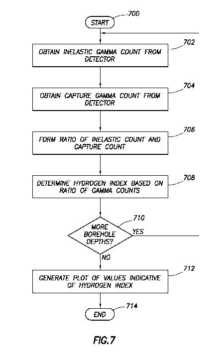
[0044] Figure 7, illustrates a flowchart of a method in accordance with an
embodiment of the disclosure which may be at least in part performed by a
computer system, such as surface computer 22 or computer system 206 in
logging tool 10. The method starts, block 700 and proceeds to obtain an
inelastic
gamma count from a gamma detector, block 702. The detector may be selected
from among a plurality Of detectors in the logging tool, as previously
described.
For example, the detector may be far detector 204B or long detector 204A
selected based on sensitivity to count statistics and the like. In block 704,
a
capture gamma count from the detector is obtained. The respective gamma
counts may be obtained, in situ, by contemporaneous operation of the pulsed
neutron source or, alternatively, by retrieval from a well log database
containing
pulsed neutron logging tool gamma count data. Further, in an embodiment, each
of the aforementioned determinations may be made at a particular borehole
depth. In yet another embodiment, the determinations may be made for a
plurality
of borehole depths. In block 706, the method forms a ratio of the inelastic
gamma
count and the capture gamma count. In an embodiment, the ratio may be formed
by dividing the inelastic gamma count by the capture gamma count. In an
alternative embodiment, the ratio may be formed by dividing the capture gamma
count by the inelastic gamma count. The method proceeds at block 708 to
determine a value indicative of a hydrogen index based on the value of the
ratio
calculated at block 706. If values indicative of a hydrogen index are to be
determined for additional borehole depths, the method proceeds via the "Yes"
branch of decision block 710 to block 702. Otherwise, the method proceeds by
the "No" branch, and a plot of values indicative of a hydrogen index is
generated,
block 712, and the method ends at block 714.
[0045] Figure 8 illustrates in greater detail a computer system 800, which is
illustrative of both the surface computer system 22 and the computer system
206
within the logging tool 10. Thus, the computer system 800 described with
respect
to Figure 8 could be proximate to the borehole during the time period within
the
tool 10 is within the borehole, the computer system 800 could be located at
the
CA 02870833 2014-10-17
WO 2013/158-127
PCT/US2013/035887
16
central office of the oilfield services company, or the computer system 800
could
be within the logging tool 10 (such as for LWD or MWD tools). The computer
system 800 comprises a processor 802, and the processor couples to a main
memory 804 by way of a bridge device 808. Moreover, the processor 802 may
couple to a long term storage device 810 (e.g., a hard drive) by way of the
bridge
device 808. Programs executable by the processor 802 may be stored on the
storage device 810, and accessed when needed by the processor 802. The
program stored on the storage device 810 may comprise programs to implement
the various embodiments of the present specification, including programs to
implement selecting a gamma detector to use in the hydrogen index
determination, calculating the ratio of the inelastic gamma count rate to
capture
gamma count rate for one or more of the detectors, calculating the value of
indicative of hydrogen index and producing a plot of the value indicative of
hydrogen index. In some cases, the programs are copied from the storage
device 810 to the main memory 804, and the programs are executed from the
main memory 804. Thus, both the main memory 804 and storage device 810 are
considered computer-readable storage mediums. The ratios and values
indicative of hydrogen index generated by the computer system 810 may be sent
to a plotter that creates a paper-log, or the values may be sent to a display
device
which may make a representation of the log for viewing by a geologist or other
person skilled in the art of interpreting such logs.
[0046] From the description provided herein, those skilled in the art are
readily
able to combine software created as described with appropriate general-purpose
or special-purpose computer hardware to create a computer system and/or
computer sub-components in accordance with the various embodiments, to
create a computer system and/or computer sub-components for carrying out the
methods of the various embodiments and/or to create a non-transitory computer-
readable media (i.e., not a carrier wave) that stores a software program to
implement the method aspects of the various embodiments.
[0047] The above discussion is meant to be illustrative of the principles and
various embodiments of the present invention. Numerous
variations and
modifications will become apparent to those skilled in the art once the above
CA 02870833 2014-10-17
WO 2013/158427
PCT/US2013/035887
17
disclosure is fully appreciated. For example, preprocessing of the data may
take
place, such as dead-time correction and environmental correction, without
affecting scope of this specification. It is intended that the following
claims be
interpreted to embrace all such variations and modifications.