Note: Descriptions are shown in the official language in which they were submitted.
CA 02871205 2014-11-17
==
METHOD, SYSTEM AND USE FOR THERAPEUTIC ULTRASOUND
FIELD
[0001] The described embodiments relate to methods, systems and uses
for
therapeutic ultrasound, and in particular, to methods, systems and uses for
therapeutic
ultrasound for treating or alleviating eye conditions.
INTRODUCTION
[0002] Eye conditions may relate to meibomian gland dysfunction. Dry
eye is a
multifactorial disease of epidemic proportions. Dry eye may be caused by
meibomian
gland dysfunction. Dry eye can be categorized into two broad categories:
aqueous
deficient dry eye and evaporative dry eye. With blockage of the eyelid
meibomian
glands and ducts there may be a reduction of lipids within the tear film. This
results in
instability of the tear film with subsequent early tear break up and
evaporation. This
ultimately leads to exposure of the corneal surface and a cascade of ocular
surface
inflammation, thus perpetuating a dysfunctional tear syndrome.
[0003] Another example eye condition is a chalazion or meibomian cyst which
is
a collection of oil or blockage of the meibomian gland and ducts. A further
example of
an eye condition is a hordeolum or stye which may be an inflamed sebaceous
gland of
Zeiss. Finally, an additional example is blepharitis which is an inflammation
of the eyelid
which may predispose subjects to aforementioned eye conditions, such as dry
eye,
chalazion, hordeolum. Other eye conditions include scarring.
[0004] There is a need for improved methods, systems and uses for
treating or
alleviating eye conditions, such as those associated with the meibomian gland
and
ducts, or at least alternatives.
1
CA 02871205 2014-11-17
SUMMARY
[0005] In a
first aspect, embodiments described herein relate to an ultrasound
device and air gap lens for treatment of an eye condition.
[0006]
Embodiments may include a contact lens with internal air chamber and the
transducer may be applied externally through the eyelid. This may enable a
longer
transducer length to cover the entire length of the meibomian glands. The
external
transducer may also be able to move along the entire length of the meibomian
glands.
[0007] The
internal air gap and lens may impede ultrasound gel or water getting
into the air gap. Ultrasound gel may get under the contact lens and irritate
the eye.
[0008] The shape
of the contact lens may vary, and in some example
embodiments may be elliptical to maximize the number of meibomian glands
treated
across the full horizontal length of the eyelid.
[0009] In
some embodiments, drug delivery (e.g. steroid) may be facilitated by
the ultrasound use. This may be referred to as phonophoresis.
[0010] In some
embodiments, an imaging device may be used or a dual
transducer could treat and image. The imaging and processing may quantify the
amount
of meibum in the glands and ductules. Post treatment imaging may show a
reduction of
meibum in the glands thus confirming that the oil was expressed.
[0011] The
device may include at least one ultrasound transducer for supplying
ultrasound waves to an area proximate to the portion of the eyelid according
to
treatment parameters. The ultrasound transducer may provide therapeutic
ultrasound
generally across the frequency range 0.2 to 10 MHz according to some
embodiments.
In other embodiments the frequency range may extend as high as 50 MHz One
example mechanism for therapeutic gain may be differential absorption of
ultrasound in
fats compared to non-fatty tissues. This increases with increasing frequency
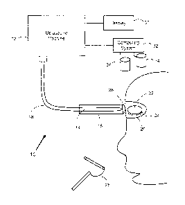
which may
support a higher frequency range.
2
CA 02871205 2014-11-17
_
[0012] These illustrative frequency ranges are not intended to
restrict.
Therapeutic Ultrasound may be generally applied across various frequency
ranges.
[0013] The air gap lens may be used to protect ocular tissue around
the eye. The
lens may be a vaulted scleral contact lens configured for placement over the
eye globe
and under the eyelid. The lens may have two layers or may comprise two lenses
configured to form a chamber of air between the layers or lenses. The chamber
of air
may protect the cornea and may block penetration of ocular tissue by the
ultrasound
waves.
[0014] The closed air chamber within the lens structure may ensure
that there is
always a built-in air barrier to ultrasound which may provide sufficient
acoustic
impedance. With such a design ultrasound contact gel can be used on the
surface of
the eyelid or periocular tissue without concern of the gel or any other fluid
getting into
the air barrier. As ultrasound does not propagate well through gases this
design would
provide high acoustic impedance and thus shield the eye from ultrasound
energy. The
different layers of the lens may also comprise an absorptive material to block
penetration of ocular tissue by the ultrasound waves. In particular, if the
ultrasound is
being applied externally through a separate ultrasound probe, then outer
surface of the
contact lens which abuts the tarsal conjunctiva of the eyelid could be made of
an
absorptive material or have an absorptive coating hat would uniformly heat and
further
act to warm the inner eyelid and the meibomian glands.
[0015] The lens could be circular. Alternatively it could be an
elliptical shape to
conform to the full horizontal length of the tarsal plate within which the
meibomian
glands are situated. Similarly the PZT transducer whether built into the
contact lens or
applied externally through a separate probe could be an elliptical shape or
other similar
shape which would allow simultaneous irradiation of the maximum number of
meibomian glands in both the upper and lower eyelids.
3
CA 02871205 2014-11-17
=
[0016] In some embodiments, the system may further comprise a lens
speculum
to elevate the eyelid from the eye globe and create airspace between eye globe
and
eyelid.
[0017] In some embodiments, the system may further comprise a
temperature
measurement mechanism for measuring the temperature of the area proximate to
the
portion of the eyelid. In some embodiments, the temperature measurement
mechanism
may comprise a thermal couple or other comparable thermal measuring device. In
some
embodiments, the thermal couple may be positioned on the contact lens. In some
embodiments, the system may further comprise an ultrasound measurement
mechanism for measuring the ultrasounds waves at the area proximate to the
portion of
the eyelid.
[0018] In some embodiments, the treatment parameters comprise a
frequency,
amplitude, on/off cycle, and a treatment period. In some embodiments, the
treatment
frequency is at least 2 MHz, at least 3 MHz, or between 3 to 5 MHz, or higher
than 5
MHz The treatment frequency may range 0.2 to 10 MHz according to some
embodiments. In other embodiments the frequency range may extend as high as 50
MHz. One example mechanism for therapeutic gain may be differential absorption
of
ultrasound in fats compared to non-fatty tissues. This increases with
increasing
frequency which may support a higher frequency range. In some embodiments, the
treatment period is between two to five minutes. The treatment time could
however be
increased to 10 to 15 minutes if a more gradual and prolonged heating was
desired.
These are non-limiting examples.
[0019] The on/off cycle may be used to pulse the ultrasound waves.
[0020] In some embodiments, the device further comprises a
controller operable
for receiving treatment data, determining the treatment parameters based on
the
treatment data, and directing the ultrasound transducer according to the
treatment
parameters.
4
CA 02871205 2014-11-17
,
[0021] In some embodiments, the eye condition is caused by
dysfunction of the
meibomian glands and wherein the area proximate to the portion of the eyelid
comprises the meibomian glands and its ductules. In some embodiments, the eye
condition is caused by dysfunction of the lacrimal glands and wherein the area
proximate to the portion of the eyelid comprises the lacrimal glands and
ductules. In
some embodiments, the eye condition is caused by dysfunction of the periocular
glands
and wherein the area proximate to the portion of the eyelid comprises the
periocular
glands and ductules. In some embodiments, the eye condition is caused by
dysfunction
of the nasolacrimal system and wherein the area proximate comprises the
nasolacrimal
system. In some embodiments, the eye condition is caused by dysfunction of the
Wolfring glands and wherein the area proximate to the portion of the eyelid
comprises
the Wolfring glands and ductules. In some embodiments, the eye condition is
caused by
dysfunction of the Krause glands and wherein the area proximate to the portion
of the
eyelid comprises the Krause glands and ductules. In some embodiments, the eye
condition is caused by dysfunction of the Zeis glands and wherein the area
proximate to
the portion of the eyelid comprises the Zeis glands and ductules.
[0022] In some embodiments, the eye condition is caused by lipids
blocked in
one or more glands of the eye and wherein the ultrasound waves heat the lipids
to
emulsify the lipids blocked in the glands and ductules and facilitate flow. In
some
embodiments, the ultrasound waves heat the lipids to approximately 40 degrees
Celsius
to increase flow and mobility of the lipids. This is a non-limiting example.
In some
embodiments, the ultrasound waves supply oscillations to move the emulsified
lipids by
creating bubbles in the emulsified lipids. In some embodiments, the ultrasound
waves
supply acoustic streaming to mobilize the emulsified lipids. In some
embodiments, the
ultrasound waves cause mircocavitation to mobilize the emulsified lipids. In
some
embodiments, the ultrasound waves stimulate circulation and lymph flow in the
area
proximate to the portion of the eyelid.
[0023] In some embodiments, the ultrasound waves breakdown scar
tissue in the
area proximate to the portion of the eyelid.
5
CA 02871205 2014-11-17
. .
. ,
[0024] In some embodiments, the ultrasound waves supply continuous
ultrasound energy. In some embodiments, the ultrasound waves supply pulsed
ultrasound energy defined by on/off cycle.
[0025] In some embodiments, the device further comprises a probe for
coupling
to the ultrasound transducer.
[0026] In some embodiments, the device is configured to provide
phased array
ultrasound to vary ultrasound waves.
[0027] In some embodiments, the ultrasound transducer comprises
movable
components that are configured to move relative to the portion of the eyelid
to vary
ultrasound waves.
[0028] In some embodiments, the device comprises an ultrasound
imaging
camera and wherein the device is operable in a therapeutic mode to heat the
area
proximate to the portion of the eyelid and a diagnostic mode to image the area
proximate to the portion of the eyelid using the ultrasound imaging camera. In
some
embodiments, the device can operate in therapeutic mode and diagnostic mode to
perform real-time imaging during treatment.
[0029] In some embodiments, an imaging device may be used or a dual
transducer could treat and image. The imaging and processing may quantify the
amount
of meibum in the glands and ductules. Post treatment imaging may show a
reduction of
meibum in the glands thus confirming that the oil was expressed.
[0030] In some embodiments, the ultrasound transducer has a concave
shape to
complement the eyelid, or the ultrasound transducer has an attachment with a
concave
shape to complement the eyelid. In some embodiments, the ultrasound transducer
has
an elliptical shape to complement the eyelid. In some embodiments, the device
further
comprises an attachment for the ultrasound transducer, wherein the attachment
comprises a protective portion for positioning over the eye globe and under
the eyelid to
6
CA 02871205 2014-11-17
õ
. .
protect eye tissue, wherein the protective portion has a concave shape to
complement
the eyelid.
[0031] In some embodiments, the eye condition is selected from the
group
consisting of dry eye, meibomian gland dysfunction, duct dysfunction, lacrimal
gland
dysfunction, periocular gland dysfunction, nasolacrimal system dysfunction,
post-
surgical scarring, and chalazion.
[0032] In another aspect, embodiments described herein provide use of
an
ultrasound device configured for treatment of dry eye, wherein the device
comprises at
least one ultrasound transducer for coupling to at least a portion of an
eyelid to supply
ultrasound waves to an area proximate to the lacrimal glands to stimulate
aqueous
production and flow from the lacrimal glands and ducts.
[0033] In another aspect, embodiments described herein provide the
use of a
high frequency ultrasound device configured for treatment of dry eye, wherein
the
device comprises at least one ultrasound transducer for coupling to at least a
portion of
an eyelid to supply ultrasound waves to an area proximate to the meibomian
gland to
stimulate meibum production and flow from the meibomian gland and ducts.
[0034] In a further aspect, embodiments described herein provide a
system for
treating an eye condition comprising: an ultrasound device comprising at least
one
ultrasound transducer for coupling to at least a portion of an eyelid to
supply ultrasound
waves to an area proximate to the portion of the eyelid according to treatment
parameters. In some embodiments, the treatment parameters comprise a
frequency, an
amplitude, on/off cycle, and a treatment period. Example frequency ranges
include 0.2
to even higher than 50 MHZ, other examples may be at least 2 MHz, at least 3
MHz,
and between 3 to 5 MHZ. Greater than 5 MHZ frequencies may also be used to
limit
depth of penetration into tissue. An example treatment period is between two
to five
minutes. Further example frequency ranges include 0.2 to 10 MHz according to
some
embodiments. In other embodiments the frequency range may extend as high as 50
MHz. One example mechanism for therapeutic gain may be differential absorption
of
7
CA 02871205 2014-11-17
. =
. .
ultrasound in fats compared to non-fatty tissues. This increases with
increasing
frequency which may support a higher frequency range. These are non-limiting
examples.
[0035] In some embodiments, the system further comprises a controller
operable
for receiving treatment data from an external source, determining the
treatment
parameters based on the treatment data, and directing the ultrasound
transducer
according to the treatment parameters.
[0036] In some embodiments, the ultrasound waves heat the area
proximate to
the portion of the eyelid.
[0037] In some embodiments, the eye condition is caused by lipids blocked
in a
gland or duct of the eye and wherein the ultrasound waves heat the area
proximate to
the portion of the eyelid to emulsify the lipids blocked in the gland or the
duct and
facilitate flow. In some embodiments, the ultrasound waves heat the lipids to
approximately 40 degrees Celsius or even higher. In some embodiments, the
ultrasound waves supply oscillations to move the emulsified lipids by creating
bubbles in
the emulsified lipids. In some embodiments, the ultrasound waves supply
acoustic
streaming to mobilize the emulsified lipids. In some embodiments, the
ultrasound waves
cause mircocavitation to mobilize the emulsified lipids. In some embodiments,
the
ultrasound waves stimulate circulation and lymph flow in the area proximate to
the
portion of the eyelid. In some embodiments, the ultrasound waves breakdown
scar
tissue in the area proximate to the portion of the eyelid. In some
embodiments, the
ultrasound waves supply continuous ultrasound energy. In some embodiments, the
ultrasound waves supply pulsed ultrasound energy.
[0038] In some embodiments, the device further comprises a probe for
coupling
to the ultrasound transducer. In some embodiments ultrasound gel can be used
as a
contact medium between the eyelid and the ultrasound transducer. In some
embodiments, the device is configured to provide phased array ultrasound. In
some
embodiments, the ultrasound transducer comprises movable components that are
8
CA 02871205 2014-11-17
configured to move relative to the portion of the eyelid to vary ultrasound
waves. In
some embodiments, the device comprises an ultrasound imaging camera and
wherein
the device is operable in a therapeutic mode to heat the area proximate to the
portion of
the eyelid using the ultrasound waves and a diagnostic mode to image the area
proximate to the portion of the eyelid using the ultrasound imaging camera. In
some
embodiments, the ultrasound transducer has a concave shape to complement the
eyelid. In some embodiments, ultrasound transducer has an elliptical shape to
complement the eyelid. In some embodiments, the device further comprises an
attachment for the ultrasound transducer, wherein the attachment comprises a
protective portion for positioning over the eye globe and under the eyelid to
protect eye
tissue, wherein the protective portion has a concave shape to complement the
eyelid. In
some embodiments, the eye condition is selected from the group consisting of
dry eye,
meibomian gland dysfunction, duct dysfunction, lacrimal gland dysfunction,
periocular
gland dysfunction, nasolacrimal system dysfunction, post-surgical scarring,
and
chalazion.
[0039] In some embodiments, the system may further comprise a roller
shaped to
complement the eyelid and applied to the eyelid to express the emulsified
lipids from the
gland or the duct. In a further aspect, embodiments described herein provide a
method
for treating an eye condition using a therapeutic ultrasound device, the
method
comprising: coupling at least one ultrasound transducer to at least a portion
of an eyelid;
and propagating ultrasound waves to an area proximate to the portion of the
eyelid
using the ultrasound transducer according to treatment parameters.
[0040] In some embodiments, the treatment parameters comprise a
frequency,
an amplitude, on/off cycle, and a treatment period. In some embodiments, the
method
may further comprise placing a contact lens over the eye globe and under the
eyelid to
protect ocular tissue around the eye. In some embodiments, the lens is a
vaulted scleral
contact lens configured to form a chamber of air. The chamber of air may be
between
lens layers of different radii of curvature or it may be behind the posterior
surface of the
contact lens and the cornea.
9
CA 02871205 2014-11-17
,
[0041] In some embodiments, the lens comprises an absorptive
material to block
penetration of ocular tissue by the ultrasound waves. The chamber of air may
also block
penetration of ocular tissue by the ultrasound waves.
[0042] In some embodiments, the method may involve using a lens
speculum to
elevate the eyelid from the eye globe and create an airspace between eye globe
and
eyelid. In some embodiments, the eye condition relates to the meibomian glands
and
wherein the ultrasound waves are supplied for the treatment period to liquefy
solidified
fats in the meibomian glands. In some embodiments, the eye condition relates
to the
glands of Zeiss with a hordeolum present and wherein the ultrasound waves are
supplied for the treatment period to liquefy fats in the glands of Zeiss when
the
hordeolum is present.
[0043] In some embodiments, the method may further comprise applying
ultrasound gel to the surface of the eyelid to act as a coupling medium
between eye
tissue and the transducer.
[0044] In another aspect, embodiments described herein provide use of an
ultrasound device configured for treatment of meibomian gland dysfunction
caused by
solidified fats, wherein the device comprises at least one ultrasound
transducer for
coupling to at least a portion of an eyelid to supply ultrasound waves to the
meibomian
glands and ductules to heat the meibomian glands and ductules and liquefy the
solidified fats.
[0045] In another aspect, embodiments described herein provide use
of an
ultrasound device configured to promote remodeling and resolution of eyelid
scar tissue
from the etiology selected from the group consisting of post-surgical, post
chalazion,
post-inflammatory, and post-infectious, wherein the device comprises at least
one
ultrasound transducer for coupling to at least a portion of the eyelid to
supply ultrasound
waves to breakdown scar tissue in the eyelid. This treatment could be combined
with
topical steroids placed directly on the dermis of the eyelid within the
coupling medium.
The ultrasound energy could facilitate steroid penetration into the eyelid
tissue and into
CA 02871205 2014-11-17
the periocular glands, in particular the meibomian glands. Ultrasound could be
used
over the eyelids or meibomian glands to promote drug delivery of other topical
medications through the process of phonophoresis
[0046] In a further aspect, embodiments described herein provide the
use of an
ultrasound device configured for treatment of an eye condition, wherein the
device is
operable in a therapeutic mode and a diagnostic mode, wherein the device
comprises at
least one ultrasound transducer for coupling to at least a portion of an
eyelid to supply
ultrasound waves to an area proximate to the portion of the eyelid to diagnose
the eye
condition in the diagnostic mode and to treat the eye condition according to
treatment
parameters in the therapeutic mode.
[0047] In some embodiments, the ultrasound device is configured to
operate in
diagnostic mode and therapeutic mode concurrently to provide real-time imaging
during
treatment.
[0048] In another aspect, embodiments described herein provide the
use of an
ultrasound device configured to facilitate fluid flow down the nasolacrimal
system,
wherein the device comprises at least one ultrasound transducer for coupling
to at least
a portion of an inner canthal region of the eye to supply ultrasound waves to
an area
proximate nasolacrimal system according to treatment parameters.
[0049] In another aspect, embodiments described herein provide the
use of an
ultrasound device configured to break up stones within the nasolacrimal
system,
wherein the device comprises at least one ultrasound transducer for coupling
to at least
a portion of an inner canthal region of the eye to supply ultrasound waves to
an area
proximate nasolacrimal system according to treatment parameters, wherein the
treatment parameters comprise a treatment frequency and a treatment period.
11
CA 02871205 2014-11-17
. .
DRAWINGS
[0050] For a better understanding of embodiments of the systems,
methods and
uses described herein, and to show more clearly how they may be carried into
effect,
reference will be made, by way of example, to the accompanying drawings in
which:
[0051] FIG. 1 shows a diagram of a system for eye conditions using
therapeutic
ultrasound according to some embodiments;
[0052] FIG. 2 shows a diagram of a meibomian gland according to some
embodiments;
[0053] FIG. 3 shows a diagram of a use of therapeutic ultrasound for
eye
conditions according to some embodiments;
[0054] FIG. 4 shows a diagram of a method using ultrasound for eye
conditions
according to some embodiments;
[0055] FIG. 5 shows another diagram of a use of therapeutic
ultrasound for eye
conditions according to some embodiments;
[0056] FIG. 6 shows a diagram of a use of therapeutic ultrasound with an
attachment for eye conditions according to some embodiments; and
[0057] FIG. 7 shows another diagram of a use of therapeutic
ultrasound with an
attachment for eye conditions according to some embodiments.
[0058] FIG. 8 an example external transducer and contact lens to
protect the eye
according to some embodiments.
[0059] FIG. 9 shows an example internal transducer and contact lens
to protect
the eye according to some embodiments.
[0060] FIG. 10 an example system including a transducer and a contact
lens with
air gap according to some embodiments.
12
CA 02871205 2014-11-17
[0061] FIG. 11 an example prototype lens.
[0062] FIG. 12 another example system including a transducer and a
contact lens
with air gap according to some embodiments.
[0063] FIG. 13 illustrates an example thermal model.
[0064] FIG. 14 illustrates an example acoustic source model.
[0065] FIG. 15 illustrates a chart of temperature rise against time
for the external
transducer configuration.
[0066] FIG. 16 illustrates a contact lens area proximate to FSA and
ultrasound
gel.
[0067] FIG. 17 illustrates a chart of temperature rise against time for
FSA.
[0068] FIG. 18 illustrates example vacuum molded PVDF to construct
sub-tarsal
devices.
[0069] FIG. 19 illustrates example prototypes for PZT internal
transducers for
embedding within air gap contact lens.
[0070] FIGS. 20 and 21 illustrate attenuation as a function of frequency.
[0071] FIGS. 22 to 25 illustrate example prototypes for PZT internal
transducers
for embedding within air gap contact lens.
[0072] Fig. 26 illustrates a graph from measured attenuation of
porcine eyelid.
[0073] Figs. 27 and 28 illustrate schematics of experimental
embodiments.
[0074] Figs. 29a and 29b illustrate example graphs of the relative field
intensities.
[0075] Figs. 30a and 30b illustrate examples graphs of heating
curves.
13
CA 02871205 2014-11-17
[0076] Figs. 31a, 31b, 32a, 32b, 33a, 33b, 36a and 36b illustrate
example graphs
of temperature curves.
[0077] Figs 34a, 34b, and 35 illustrate example graphs of time
curves.
[0078] The drawings, described below, are provided for purposes of
illustration of
the aspects and features of various examples of embodiments described herein.
For
simplicity and clarity of illustration, elements shown in the figures have not
necessarily
been drawn to scale. The dimensions of some of the elements may be exaggerated
relative to other elements for clarity. Further, where considered appropriate,
reference
numerals may be repeated among the figures to indicate corresponding or
analogous
elements.
DESCRIPTION OF VARIOUS EMBODIMENTS
[0079] It will be appreciated that numerous specific details are set
forth in order to
provide a thorough understanding of the exemplary embodiments described
herein.
However, it will be understood by those of ordinary skill in the art that the
embodiments
described herein may be practiced without these specific details. In other
instances,
well-known methods, procedures and components have not been described in
detail so
as not to obscure the embodiments described herein. Furthermore, this
description
should be considered as describing implementation of the various embodiments
described herein.
[0080] The described embodiments relate to methods, systems and uses for
therapeutic ultrasound for treating or alleviating eye conditions, such as dry
eye and
other conditions associated with gland dysfunction and eyelids.
[0081] Eye conditions may relate to meibomian gland dysfunction. For
example,
one of the underlying causes of dry eye may be meibomian gland dysfunction.
Other
example eye conditions include chalazion, meibomian cysts, hordeolum, stye,
blepharitis and so on. Meibomian gland dysfunction may occur due to a variety
of
14
CA 02871205 2014-11-17
p ,
factors. These factors range from keratinization of ductules, inflammation of
ducts,
solidification of lipid secretions, and atrophy of glands themselves. A
meibomian gland
blockage, dry eye, and other eye conditions may be ameliorated with heat. The
heat
required to break up oil secretions involves a treatment that sufficiently
warms the eyelid
for a period of time. For example, heat treatment may warm the eyelids to 40
degrees
Celsius for four minutes. This is an example only and other time periods may
be used
depending on temperatures used. Hot water (wet towel) compresses may be used
to
apply wet heat to the eyelids. Although efficacious, patient compliance may be
a
problem and the technique may be error prone as the compress may not warm
eyelids
to sufficiently warm temperatures. As another treatment approach, a product
may heat
the eyelids and massage them to facilitate expression of oil contents.
Although
efficacious this treatment product may be costly and a transducer head may
have to be
purchased for each patient.
[0082] The described embodiments relate to methods, systems and uses
for
therapeutic ultrasound for eye conditions by providing heat and oscillatory
ultrasound
energy to the eyelids, meibomian glands, lacrimal gland, or other glands and
areas
proximate eye. By using therapeutic ultrasound energy the depth of tissue
penetration
may be minimized while the amount of energy delivered to the tissue may be
maximized.
[0083] For therapeutic ultrasound, the frequency used typically ranges from
0.2 to
10 MHz depending on tissue depth penetration. Absorption and therefore energy
deposition increases with increasing frequency. Since the eyelid is only
several
millimeters in thickness a range of different frequencies may be used by the
described
embodiments to heat the eyelid and meibomian glands. The ultrasound transducer
may
provide therapeutic ultrasound generally across the frequency range 0.2 to 10
MHz
according to some embodiments. In other embodiments the frequency range may
extend as high as 50 MHz. Alternatively, a lower frequency therapeutic
ultrasound may
be used at a higher power setting or a longer duration to generate sufficient
heat. The
use of therapeutic ultrasound may help emulsify blocked fats by two distinct
example
CA 02871205 2014-11-17
= = =
mechanisms. For example, the high frequency ultrasound may provide heat energy
to
fats in the gland. The heat energy delivered may liquefy solidified fats. The
oscillations
would further act to mobilize oil movement through the formation of small
bubbles in the
oil medium. This may be referred to as microcavitation. Accordingly, the use
of
therapeutic ultrasound may heat the gland to liquefy fat blockage and create
microcavitation.
[0084] Ultrasound energy may further facilitate movement of oil
within the glands
and/or ductules through acoustic streaming. The therapeutic ultrasound may
also
stimulate circulation in the eyelid and meibomian gland, which may promote
clearance
of inflammatory mediators. Further, the therapeutic ultrasound may help
breakdown and
remodel scar tissue in the eyelid, which may be the result of a chalazion, or
other
trauma or infection/inflammation to eyelid. Therapeutic ultrasound may be used
post-
surgically on the eyelid to reduce scar formation and facilitate healing of
tissue after
eyelid surgery. These eyelid surgeries could include but would not be limited
to
blepharoplasty, ptosis repair, entropion repair, ectropion repair, excisional
and incisional
biopsies and so on. When used to remodel scar tissue therapeutic ultrasound
could be
combined with other treatments such as intralesional injection of
corticosteroids or
topical application of steroids and other anti-inflammatories. In this
situation therapeutic
ultrasound may facilitate penetration of and distribution of medications
through the
process of phonophoresis. Ultrasound could be used over the eyelids or
meibomian
glands to promote drug delivery of other topical medications through the
process of
phonophoresis
[0085] Alternatively, or in conjunction with being directed on the
meibomian
glands, ultrasound energy could be directed superotemporally in the orbit to
focus
energy on the lacrimal gland. This acoustic energy may stimulate secretion of
tears from
the lacrimal gland through to the lacrimal ducts.
[0086] In addition to aforementioned applications of therapeutic
ocular
ultrasound, if the power and frequency settings are varied, ultrasound energy
may be
16
CA 02871205 2014-11-17
directed medially at the nasolacrimal duct apparatus to resolve partial and
complete
blockages. Ultrasound energy can be used to resolve blockages of the upper and
lower
canalaculi, the lacrimal sac, or the nasolacrimal duct itself. The ultrasound
could be
used at lower settings to facilitate flow through the entire apparatus in
partial blockages
or functional blockages. The ultrasound may be used at higher energy settings
to break
up stones if they are obstructing the passages. This technique may be directed
to
stones located anywhere along the entire course of the nasolacrimal system.
This
ultrasound method may be analogous to the lithotripsy used for treatment of
kidney
stones. A small probe attachment may be used for this application as it would
allow the
clinician to focus or broaden ultrasound energy around the desired location.
[0087] Referring now to FIG. 1 there is shown a system using
therapeutic
ultrasound for eye conditions. The system 10 is operable to connect a
transducer head
16 to an ultrasound machine 12 via connector 18. The transducer head 16 may be
shaped to complement various portions of the eye. Further, the transducer head
may
include a small probe attachment sized proportional to the portion of the eye
to be
treated in order to focus or broaden energy on the specific treatment portion
of the eye.
[0088] The transducer head 16 may also include a piezoelectric
crystal 14 or
numerous crystals as a non-limiting illustrative example. Other example
transducer
heads 16 are electromagnetic transducers, PZT transducers, and so on. This is
an
example transducer and other types may be used. For example, transducer may be
constructed from a piezeoelectric ceramic with perovskite structure, such as
lead
zirconate titanate (PZT) its varieties. The transducer may also be made from a
piezoelectric polymer, such as polyvinylidene fluoride (PVDF) film (or other
material) for
example.. Piezoceramics may include PZT and PZT-varieties, barium titanate,
lead
titanate, lead zirconate titanate, potassium niobate, lithium niobate, lithium
tantalate,
sodium tungstate, zinc oxide, and so on.
[0089] In this illustrative example, the system 10 is operable to
deliver energy
through the ultrasound machine 12 to the transducer head 16 coupled to the
closed
17
CA 02871205 2014-11-17
. , .
eyelid 24. A gel 20 may be used as a coupling medium to allow direct contact
of the
transducer head to the closed eyelid 24. The external transducer may also be
able to
move along the entire length of the meibomian glands.
[0090] Embodiments may include a contact lens with internal air
chamber and the
transducer may be applied externally through the eyelid. This may enable a
longer
transducer length to cover the entire length of the meibomian glands. The
internal air
gap and lens may impede ultrasound gel or water getting into the air gap.
Ultrasound
gel may get under the contact lens and irritate the eye.
[0091] The shape of the contact lens may vary, and in some example
embodiments may be elliptical to maximize the number of meibomian glands
treated
across the full horizontal length of the eyelid.
[0092] The ultrasound machine 12 may operate at a varying
frequencies
depending on the treatment parameters. For example, a lower frequency at a
higher
power (or amplitude) may also be used. The ultrasound transducer may provide
therapeutic ultrasound generally across the frequency range 0.2 to 10 MHz
according to
some embodiments. In other embodiments the frequency range may extend as high
as
50 MHz. The delivery of ultrasound energy may be continuous or pulsed. Pulsed
energy
may allow for a slower heat rise than continuous ultrasound energy at the same
intensity. A pulsed ultrasound application may take longer to warm the tissue
but may
provide a larger safety margin and reduce chance of tissue burn. This is an
example
configuration of a system.
[0093] In another aspect, there is provided a system for treating an
eye condition
comprising an air gap lens and one or more ultrasound transducers. The
ultrasound
transducer may be positioned within or on the air gap lens, as described
herein. Fig. 9
provides an example representation.
[0094] Referring back to FIG. 1, the ultrasound machine 12 is
configured for
treatment of an eye condition, such as dry eye, dysfunction of the meibomian
gland,
18
CA 02871205 2014-11-17
, = =
,
lacrimal gland, periocular gland, and nasolacrimal system, chalazion, and
scarring. The
ultrasound transducer 16 is adapted for eye treatment and suitable for
coupling to at
least a portion of an eyelid to supply ultrasound waves to the eyelid
according to
treatment parameters. The treatment parameters may include a frequency, an
amplitude (e.g. power), an on/off cycle (e.g. for pulses), a phase, and a
treatment
period. An example treatment frequency range is between 0.2 MHz, 10 MHz, up to
50
MHz and further examples are provided herein. The treatment parameters may
specify
a range of frequencies and amplitudes for the ultrasound waves.
[0095] The ultrasound machine 12 may also be connected to a
temperature
measurement device (e.g. measurement tool 25 of FIG. 5) that is configured to
measure
temperature elevations induced by deposition of acoustic energy to the eyelid
by the
ultrasound transducer 16. If the temperature increases above the range a
warning alert
may be generated to adjust the treatment parameters or the transducer 16 may
be shut
down automatically to avoid damage to the eye or eyelid. If the temperature
decreases
below the range an alert may be generated to adjust the treatment parameters.
An
example temperature measurement device may be a thermocouple. A measurement
device may also measure ultrasound waves and provide the measurement data to
ultrasound machine 12. If the ultrasound waves pass a predetermined safety
threshold
then the transducer 16 may automatically shut down or adjust to stay within
the safety
threshold. An example measurement device for ultrasound waves is a hydrophone.
[0096] The frequency range may provide sufficient ultrasound energy
to heat the
treatment area of the eye. For example, the frequency range of 0.2 MHz to 50
MHz or
higher may provide sufficient ultrasound energy to heat the treatment area of
the eye to
40 degrees Celsius. Tissue denaturation may start at temperatures over 43 when
applied for long treatment periods, such as over 200 minutes. The treatment
period may
be proportional to the treatment frequency, as a lower frequency may require a
longer
period and vice versa. Example treatment periods range between thirty seconds
to
twenty minutes, one minute to ten minutes, and two to five minutes, or longer
depending
19
CA 02871205 2014-11-17
,
on the treatment parameters. These are non-limiting example treatment periods
and
frequencies and others may be used.
[0097]
The eye condition may be caused by lipids blocked in a gland of the eye
and the ultrasound waves may heat the treatment area of the eyelid to emulsify
the
lipids blocked in the gland. As noted herein, the ultrasound waves may supply
oscillations to move the emulsified lipids by creating bubbles in the
emulsified lipids,
may supply acoustic streaming to mobilize the emulsified lipids, may cause
mircocavitation to mobilize the emulsified lipids, stimulate circulation in
the area
proximate to the portion of the eyelid, and breakdown scar tissue in the area
proximate
to the portion of the eyelid.
[0098]
The ultrasound machine 12 may include a controller to receive treatment
data from a data source (e.g. computing system 32 or other third party
networked
system). The controller may process the treatment data to determine the
treatment
parameters and direct the ultrasound transducer 16 to propagate ultrasound
waves
according to the treatment parameters. The treatment data may define eye
condition,
measurements, location, and so on. The ultrasound machine 12 may also connect
to an
ultrasound imaging camera. The ultrasound machine 12 is operable in a
therapeutic
mode to heat the area proximate to the portion of the eyelid. The ultrasound
machine 12
is operable in a diagnostic mode to image the area proximate to the portion of
the eyelid
using the ultrasound imaging camera. The imaging camera could visualize the
consolidated meibum in the meibomian gland and its ductules. It could also
quantify the
amount of meibum in the glands. A reduction in meibomian gland volume would
confirm
that oil was expressed out of the glands and ductules The diagnostic mode may
be
used to collect treatment data regarding the eye condition.
[0099] The system 10 may also include a roller 26 to express oil secretions
from
the meibomian glands. The roller 26 may have various shapes, such as a curve
or
concave shape to complement the eye.
CA 02871205 2014-11-17
,
[00100] The piezoelectric crystal 14 may be a PZT-8 or similar
material, or may
use other techniques such as electromagnetic. The ultrasound machine 12 may be
powered by various means such as by a standard current or an internal battery.
The
transducer head 16 may be a plastic material forming a sealed transducer, a
head
cover, and so on. The transducer head 16 may have various shapes and
components,
such as a curved or concave shape complementary to eyelid, elliptical shape, a
flat
head, thin plates extension, probe attachments, and so on. The piezoelectric
crystal 14
may contract and expand based on the ultrasonic frequency signals supplied by
the
ultrasound machine 12 to generate ultrasonic pressure waves which are coupled
to the
closed eyelid 24 via transducer 16. Any oscillating component with a
transducer head
16 may provide ultrasound energy through the probe to the eyelid, meibomian
glands,
lacrimal gland, periocular glands or nasolacrimal system. The transmission of
the
pressure waves into the closed eyelid 24 may be enhanced by the gel 20. The
ultrasonic pressure waves propagate through the closed eyelid 24 to the
meibomian
glands, lacrimal gland, periocular glands or nasolacrimal system.
[00101] Transducer 16 may be held in place by an adhesive, a clip, or
by a health
assistant for a treatment period. When the treatment is applied by a health
assistant the
probe may be slowly moved over the closed eyelid 24. Moving the transducer
head 16
during treatment may be important because of the following effects: to smooth
out
irregularities of the near field, to minimize hotspot formation, to reduce
irregularities of
absorption that might occur due to reflection, interfaces, standing waves,
refraction, and
differences in tissue thermal conduction or blood flow. It is estimated that
at an output 1
W/cm2 there is a rise of 0.8 C/min if vascular cooling effects are ignored.
[00102] Alternatively, instead of the transducer head 16 being moved
by the
clinician over the tissue of the eyelid 24, the transducer head 16 may be
stationary or
fixed to the eyelid 24. If mobile, a ultrasound transducers could be employed
and this
may have a single active element that both generates and receives high
frequency
sound waves, or two paired elements one for transmitting and one for
receiving. In
21
CA 02871205 2014-11-17
contrast, if stationary, a head 16 with multiple components could vary the
ultrasound
beam applied from the transducer.
[00103] The transducer head 16 may have moving components within the
head
that vary the ultrasound beam applied from the transducer 16.
[00104] A phased array may be used to vary the application of the
ultrasound
across the treatment field. This may allow the clinician to simply apply the
transducer 16
(or probe attached thereto) to the eyelid 24 or fasten/adhere it in place
without
constantly moving the transducer 16 (or probe attached thereto). With this
phased array
the risk of having a standing wave or a hotspot may be greatly reduced. The
phased
array could be arranged in a strip (linear array), a ring (annular array), a
circular matrix
(circular array), or a more complex shape such as an ellipse that would
conform to the
shape of the eyelids.
[00105] The system 10 may also include a display for displaying images
and video
from ultrasound machine 12 and a computing system 32 with a processor and
memory
34 for processing captured data, images and video. The computing system 32 may
be
operable to store data/images/video in memory 34 and/or an imaging database
36. The
transducer 16 may have an imaging component 28. The ultrasound 12 and
transducer
16 may be used in a diagnostic setting to image the gland and eyelid 24, as
well as a
therapeutic setting to heat the eyelid 24 and gland. The gland and surrounding
tissues
could be imaged in real time as the treatment is provided by the transducer
head 16. A
dual transducer may be used to image and treat. The images may provide a
visual
indication of treatment progression for a patient.
[00106] The imaging camera could visualize the consolidated meibum in
the
meibomian gland and its ductules. It could also quantify the amount of meibum
in the
glands. A reduction in meibomian gland volume would confirm that oil was
expressed
out of the glands and ductules.
22
CA 02871205 2014-11-17
= ' .
[00107] Referring now to FIG. 2 there is shown a diagram of a
meibomian gland
and duct 40, with a fat blockage 44. There is also shown an illustrative view
of the
meibomian gland and duct 40. As shown the meibomian gland and duct 40 may be
located in the eyelid 24 near the eye globe 42.
[00108] Ultrasound energy may be passed into the ocular tissues, which may
incite inflammation and potentially cause cataract formation. In accordance
with
embodiments described herein, systems, methods and uses may involve a vaulted
scleral contact lens 22. The lens 22 may be placed over the eye globe and
under the
eyelids 24 to form a chamber of air. The chamber of air may be between lens
layers or
the posterior surface of the contact lens and the cornea itself. Since
ultrasound energy
does not pass well through gases this vaulted chamber may act as a barrier to
ultrasound transmission effectively shielding the eye from the ultrasound
energy.
Alternatively, a lens speculum may be applied to the eye to elevate eyelid 24
from eye
globe and create an airspace between eye globe and eyelid 24.
[00109] The transducer 16 may be applied to eyelid at different angles and
directions. Referring now to FIG. 3 there is shown uses of therapeutic
ultrasound for eye
conditions. In one example, a transducer head 16 may have a curved shape to
complement the eyelid 24. The transducer head 16 may propagate ultrasound
waves
towards the eyelid 24 and eye globe 42 to liquefy fat blockage 44 in the gland
40. A lens
22 may create or include a chamber of air 46 to protect the eye globe 42. The
lens 22
may be placed over the eye globe 42 and under the eyelids 24 to form a chamber
of air
46 between the posterior surface of the contact lens 22 and the cornea itself.
The
chamber of air may also be within the lens, between layers of the lens.
[00110] The contact lens could also be made of an absorptive material
that does
not allow penetration of ultrasound energy, or the chamber of air (e.g. air
gap) may
block penetration of ultrasound energy. In some cases the contact lens may
form a
sufficient barrier so that it would not need to be vaulted off the globe.
Alternatively, a
lens speculum (not shown) may be applied to the eye to elevate eyelid 24 from
eye
23
CA 02871205 2014-11-17
= = =
globe 42 and create an airspace between eye globe and eyelid 24. In another
example,
the transducer head 16 may propagate ultrasound waves away from the eye globe
42
using thin plates which form part of transducer head 16.
[00111] Referring now to FIG. 5 there is shown another diagram of a
use of
therapeutic ultrasound for eye conditions. The transducer head 16 may have a
curved
shape to complement the eyelid 24. The transducer head 16 may propagate
ultrasound
waves towards the eyelid 24 and eye globe 42. A lens 22 may be positioned on
top of
the cornea and covered by the eyelid 24. The lens 22 may be vaulted to protect
eye
globe 42 by creating a chamber of air between the posterior surface of the
contact lens
22 and the cornea itself. The lens 22 may also include multiple layers
creating a
chamber of air. The contact lens 22 may also be made of an absorptive material
that
does not allow penetration of ultrasound energy. In this case the contact lens
would
form a sufficient barrier so that it would not need to be vaulted off the
globe. Coupling
gel 23 may be applied on top of the eyelid 24 to act as a coupling medium
between the
tissue and the transducer 16. Ultrasound waves may be transmitted by the
transducer
16 into the eyelid 24.
[00112] A temperature and attenuation measurement device may be
positioned
proximate to the lens or other area to collect and record temperatures and
attenuation
measurements to monitor heating of eye 42. For example, a measurement tool 25
may
be positioned on the lens 22 in order to take temperature measurements. The
measurement tool 25 may be a thermocouple. The measurement tool 25 may provide
temperature data to controller. If the temperature exceeds a safety threshold
the
controller may automatically shut off the transducer 16 to ensure the eye 42
is not
damaged, automatically adjust the treatment parameters to reduce the
temperature, or
send an alert notification. The measurement tool 25 may be positioned on the
lens 22
using glue or other adhesive. It may also be built within the lens 22.
[00113] Referring now to FIG. 4 there is shown a method 100 of using
high
frequency ultrasound for eye conditions. The method 100 may be use high
frequency
24
CA 02871205 2014-11-17
. . .
..
ultrasound to liquefy solidified fats in the meibomian gland, or other
glands/ducts. At
102, a clinician may administer a drop of tetracaine or equivalent topical
anesthetic unto
the eye. At 104, a lens 22 may be placed onto the eye. At 106, the ultrasound
transducer 16 propagates the high frequency ultrasound waves (such as 0.2 to
50
MHz). The ultrasound transducer 16 may be affixed on or within the lens 22.
The
ultrasound transducer 16 may also be applied to both closed eyelids 24 through
a
coupling gel 20 medium for a treatment period, such as for example a two to
five
minutes treatment for each eye, or for longer depending on the frequency.
After the
heating treatment, at 108, a mechanical roller may be used to express oil
secretions
from the meibomian glands. This may occur while the contact lens 22 shield is
still in
place. For example, this roller may be applied from a proximal to distal
direction in the
direction of the meibum flow within the glands themselves. Alternatively, a
cotton swap
(e.g. Q-tip) or other instrument may be used to guide oil. Post treatment, the
patient
may be placed on a short course of topical steroids (or NSAIDs) to minimize
any post-
procedural inflammation.
[00114] Referring now to FIG. 6, there is shown a diagram of a use of
therapeutic
ultrasound with an attachment for eye conditions according to some
embodiments. The
attachment 52 may couple to the transducer 16 in order to propagate ultrasound
waves
to the eyelid 24. The attachment 52 may include a protective portion 50 shaped
to
complement the eye 42 and protect the eye 42 from the ultrasound waves. The
attachment 52 and protective portion 50 may clip onto the patient's head or
eye 42 (or
otherwise attach) for the duration of the treatment period. Embodiments may
include an
external transducer shaped to complement the gland for treatment. The
transducer may
be of a longer length than the air gap lens to maximize treatment area. The
external
transducer may also be able to move along the entire length of the meibomian
glands.
[00115] Referring now to FIG. 7, there is shown another diagram of a
use of
therapeutic ultrasound with an attachment for eye conditions according to some
embodiments. The attachment 56 may couple to the transducer 16 in order to
propagate ultrasound waves through the eyelid 24 but away from eye globe 42.
The
CA 02871205 2014-11-17
attachment 56 is shaped to complement the eye 42 and eye lid 24 and position
there
between. In this example, the ultrasound waves propagate away from the eye 42
to
reduce chance of harm due to heat. This may protect the eye 42 from the
ultrasound
waves. The attachment 56 may clip onto the patient's head or eye 42 (or
otherwise
attach) for the duration of the treatment period. This is another example of
an external
transducer which may be used with the air gap lens.
[00116] As described herein, ultrasound energy may be passed into the
ocular
tissues, which may harm the eye. In accordance with embodiments described
herein,
systems, methods and uses may involve a contact lens 22. The lens 22 may
include a
chamber of air created by lens layers. The lens 22 may be placed over the eye
globe
and under the eyelids 24. the lens 22 may form or provide a chamber of air to
protect
the cornea. The chamber of air may act as a barrier to ultrasound transmission
effectively shielding the eye from the ultrasound energy. Alternatively, a
lens speculum
may be applied to the eye to elevate eyelid 24 from eye globe and create an
airspace
between eye globe and eyelid 24.
[00117] Dry eye is a complex disorder that affects a significant
portion of the
population. A form of the disease is Evaporative dry eye disease which is a
disorder of
the ocular surface and tear film causing pain and low vision in a significant
portion of the
adult population. The most common cause is obstructive meibomian gland
dysfunction
("MGD"), whereby the meibomian glands secrete abnormally keratinized, viscous
meibum with a melting point approximately 3-4 C higher than normal. Dry Eye is
typically treated with heat, aiming to liquify the solidified meibum at the
meibomian
ducts. The ocular surface is coated by a tear/lipid bilayer. The lipid
functions to provide
a smooth optical surface, and retard tear evaporation. Dry eye may be caused
by
obstructed meibomian glands. Reduced meibum may lead to increased and
excessive
tear evaporation.
[00118] Embodiments described herein may reduce or treat dry eye using
an
ultrasound hyperthermia device with a contact lens. There may be an internal
26
CA 02871205 2014-11-17
õ =
-
transducer contained within a contact lens with an internal air gap. The
internal
transducer may be of polyvinylidene fluoride (PVDF) film (or other material)
for example.
This is an example transducer and other types may be used. For example,
piezoelectric
transducer may be constructed from a piezeoelectric ceramic with perovskite
structure,
such as lead zirconate titanate (PZT) its varieties. The transducer may also
be made
from a piezoelectric polymer, such as PVDF. Piezoceramics may include PZT and
PZT-
varieties, barium titanate, lead titanate, lead zirconate titanate, potassium
niobate,
lithium niobate, lithium tantalate, sodium tungstate, zinc oxide, and so on.
[00119] A prototype of this device may be built in a planar geometry
to test its
feasibility. Ex vivo experiments with porcine eyelid and cornea tissue may be
performed
with the device with low amplitudes (30-35 V) and a relatively low duty cycle
(25%) as
an illustrative example. A temperature rise of 4.5 C in the eyelid may be
achievable in a
short timeframe. A vacuum mould may be used to form a spheroidal concavity in
a
PVDF film. This film may then be fixed between two contact lenses (created an
air gap)
providing an air backing to the transducer, with the electrical connections
contained
inside this gap.
[00120] Dry eye is a complex, multifactorial disorder of the ocular
surface and tear
film due either to tear deficiency or excessive tear evaporation. It affects
vision and
comfort in a significant portion of the population
[00121] The meibomian glands are modified sebaceous glands diffusely
located
within the inner tarsal plate, numbering approximately 25 and 20 in the upper
and lower
lids, respectively. They are responsible for the secretion of meibum, the
lipid portion of
the tear layer that serves several purposes. Primarily the meibomian lipid is
a
hydrophobic seal on the aqueous tear film, preventing its evaporation and
enhancing
the film stability through a reduced surface tension. Like Dry Eye, MGD is a
broad
collection of different conditions with many causes. However, the most common
clinical
form of MGD is obstructive, diagnosed according to reduced excretion or
abnormality of
the meibum. The common case finds obstructive MGD, where the ducts by which
27
CA 02871205 2014-11-17
, .
. ,
meibum reaches the muco-aqueous surface are blocked by abnormally viscous,
keratinized meibum. Ultimately, MGD entails that insufficient levels of
meibomian lipid
are present for sealing the aqueous tear film.
[00122] A method of treatment for evaporative dry eye caused by MGD
has been
heat therapy in the form of warm compresses and/or manual gland expression
through
mechanical pressure. Meibomian lipid is liquid at lid temperature in healthy
patients,
melting at 32-40 C, however abnormal meibum has an elevated secretion
temperature
by approximately 3 C. Studies of the chemical composition of meibum have found
an
increase in phase transition temperature of 4 C, defined by several parameters
of inter-
molecular order. Hence, heat therapy aims to liquify the keratinized meibum at
the
meibomian ducts by raising the temperature of the tarsal plate. Careful
application of
heat to the eyelids may increase the thickness of the tear lipid layer.
Treatment methods
that use heat sources may apply heat to the outer surface of the eye, where
efficacy of
heat applied to the outer surface of the eyelid is debatable since the applied
heat must
diffuse through the dense muscle tissue of the tarsal plate with a strong
vascular supply.
This may be an even greater impediment for patients attempting to self-
administer warm
compresses since care must be taken to ensure the compresses remain at a
constant,
elevated temperature to provide an effective heat source.
[00123] Embodiments described herein may use High Focused Intensity
Ultrasound (HIFU). HIFU may be applied with relatively low duty cycles ( 0%),
which
allows the tissue to cool and achieve a stable temperature increase within the
39-44 C
regime. Increasing the duty cycle while concomitantly decreasing the amplitude
results
in comparable power deposition to HIFU, but with a lower ultrasonic intensity.
Given the
melting temperature of keratinized meibum at -42 C, this range may be used for
a mild
ultrasound hyperthermia treatment.
[00124] Embodiments described herein may an ultrasound device for mild
hyperthermia in the tarsal plate. Embodiments described herein may elevate the
temperature of the eyelid interior to the melting point of abnormal meibomian
lipid, taken
28
CA 02871205 2014-11-17
as 41-43 C¨a regime demonstrated effective. Due to the strong vascular supply
of the
tarsal plate, the interior of the eyelid may be assumed to be near the
temperature of
blood, at around 37 C.
[00125] Embodiments described herein may use a device that consists
of a
transducer within a large scleral contact lens with an air gap, wherein the
transducer is
attached to the lens (affixed thereto or within), which is in contact with the
conjunctival
epithelium. Inside the air gap lens, the transducer is air-backed and hence
reflects
essentially all acoustic energy forwards through the front lens into the
tarsal plate. This
is a safety consideration, as the application of heat could cause corneal
deformation,
possibly affecting or impairing vision. As low a temperature rise in the
cornea as
reasonably possible may be desired, such as below the 50 C upper bound. An
extremely conservative limit of <40 may be used, corresponding to a maximum 6
C
rise given the ocular surface temperatures measurements in the range 32-34 C
have
been reported. Thus the ultrasonic energy propagates outwards towards the
tarsus,
delivering heat directly to the Meibomian glands. The acoustic impedance
mismatch of
the transducer and air reacts essentially all pressure waves away from the
cornea,
which is an important safety consideration discussed. The device may include a
high
frequency lead-zirconium titanate (e.g. PZT) piezoceramic transducer in some
embodiments.
[00126] To demonstrate feasibility as a treatment device, a prototype may
be
constructed with a flat geometry with contact lens material and a 21 MHz PVDF
film.
This example illustrative geometry was elected to mimic the desired lens
configuration
while simplifying construction. In addition, a theoretical model of heat
delivery due to
acoustic pressure waves may be developed for this simplified geometry and
compared
with the experimental results.
[00127] Heating the external eyelid surface may require sufficient
heat
temperatures to diffuse through the strong eyelid vasculature. Temperature
rise in the
cornea may cause deformation. When heating the external surface of the eye,
the
29
CA 02871205 2014-11-17
=
temperature of the outer eyelid is higher than the temperature of the inner
eyelid. That
is, a linear decrease may be proportional to depth. Equilibrium may be
established over
time.
[00128] Treatment devices and systems in accordance with embodiments
described herein may heat tarsal plate to 41 C to 43 C. Treatment devices and
systems
in accordance with embodiments described herein may not deposit ultrasonic
energy
into cornea. Treatment devices and systems in accordance with embodiments
described herein may keep cornea under 40 C. Treatment devices and systems in
accordance with embodiments described herein may obtain a reasonable change in
temperature for a treatment timespan. These are illustrative examples.
[00129] Embodiments described herein may involve use of a contact
lens to
protect an eye during treatment of the eye with a ultrasound device. As
described
herein, there may also be a measurement tool 25 which may be a thermocouple.
As a
safety mechanism a thermocouple could be placed in either the front side, back
side, or
both sides of the contact lens. This thermocouple may trigger the ultrasound
device to
turn off if the temperature was raised to an unsafe level (eg. 48 degrees
celsius). This
thermocouple may also give real time active feedback of temperature thus
giving the
technician/doctor the ability to modulate the ultrasound settings to achieve a
safe and
effective hyperthermia. The modulation and adjustments may be automatically
configured as well. The degree of hyperthermia could also be measured and thus
modulated by other means such as infrared.
[00130] Referring now to Figure 8 there is shown an example
embodiment that
may involve a contact lens 70a, 70b to protect the eye. The contact lens 70a,
70b
includes an inner lens 70b and an outer lens 70a and spaced apart to create an
air gap
72 (e.g. chamber of air). The inner lens 70b and outer lens 70a may be
attached at
ends. The inner lens 70b may be positioned to protect the cornea 80. The inner
lens
70b and outer lens 70a may be positioned under the eyelids 78. The contact
lens 70a,
70b protects the eye during application of ultrasound energy by transducer 74
and
CA 02871205 2014-11-17
coupling 76 via the air gap 72 which may reflect acoustic energy. This
configuration and
implementation may provide efficient manufacture and use. In this example, an
external
PZT transducer 74 may be placed on top of the eyelid. The contact lens 70a,
70b with
the internal air gap 72 may be placed on cornea 80. The external PZT
transducer 74
may deposit ultrasonic heating onto eyelid 78 surface where the heat may
diffuse
inwards.
[00131] A design is proposed in which a high frequency piezo film
transducer is
mounted within a contact lens. A high frequency may be desired since the
attenuation of
an acoustic wave increases proportionally to frequency, with a corresponding
greater
heat deposition. The lens contains an interior air gap between its inner
surface
mounting the sclera and outer surface contacting the tarsal conjunctiva. These
surfaces
may be referred to as scleral and tarsal, respectively. The transducer may be
mechanically attached (or otherwise coupled) to the interior of the tarsal
surface,
moulded to the concavity of the lens. Its active face may be directed outwards
towards
the tarsal plate. The air gap provides an air backing layer to the transducer,
reflecting
essentially all of the acoustic energy forwards due to the impedance mismatch
of the
piezoelectric material and of air. This is to ensure that no pressure wave
propagates
through the scleral surface into the cornea, causing unwanted heating in the
eye.
Furthermore, the air gap acts as an insulating layer, delaying the heat
diffusion through
the front lens and eyelid into the cornea. When mounted onto the sclera, the
eyelids
would close overtop the lens, holding the device in place during the
hyperthermia
treatment. The electrical connections are contained within the air gap, with
wiring exiting
the lens through a hole sized to the wires and sealed airtight, passing
through the
palpebral fissure.
[00132] A schematic of the design when placed atop an eye is shown in
Figure 9.
The example embodiment may involve a contact lens 70a, 70b to protect the eye.
In this
example, heat from conjunctival surface within air gap 72 between the outer
lens 70a
and inner lens 70b may be used. An internal transducer 82 coupled to a RF
signal cable
84 may be positioned within air gap 72 between the outer lens 70a and inner
lens 70b.
31
CA 02871205 2014-11-17
In this example, heat is applied directed to the tarsal plate, which may
protect the outer
surface of the eyelid. The air gap 72 may protect the cornea 80. The internal
transducer
82 may be air-backed and mounted onto the inside of the air gap lens 70a, 70b,
72.
Ultrasonic heating energy is deposited directly on tarsal surface.
[00133] The feasibility of the internal air gap for protecting the cornea
during an
ultrasound hyperthermia treatment in the eyelid may be demonstrated using an
external
high frequency transducer with a protective contact lens. With this
established, a
prototype of the device with a planar geometry may be constructed, and a mild
hyperthermia experiment may be conducted to monitor the temperature increase
in
eyelid and cornea tissue. In addition, a simplified 1-dimensional model of
heat
propagation with ultrasound sources may be created in MAT-LAB to model the
heating
of the prototype's elements using a finite element analysis, for example.
[00134] Referring now to Figure 10 there is shown an example
experiment system
90 including a transducer 74 and a contact lens 70a, 70b with air gap 72 in
accordance
with the configuration shown in Figure 8. A thermocouple 86a, 86b may be
coupled to
the outer lens 70a and inner lens 70b to monitor temperatures.
[00135] A hyperthermia experiment may be performed in the
configuration seen in
Figure 10. Two thermocouples may be embedded within lens. A protective contact
lens
with an internal air gap may be built from two contact lenses with suitable
radii of
curvature to allow a gap (e.g. 2 mm) at the epicenter when the larger was fit
overtop the
smaller. This may be placed atop the cornea. The eyelid tissue may be laid
overtop this
lens. A transducer (e.g. 15 MHz) may be positioned overtop the eyelid,
applying a firm
downward pressure and coupled with ultrasound gel. A 25% duty cycle sinusoidal
RF
signal may be used as a signal source with a peak to peak voltage of 40 V. The
temperatures of both the eyelid and the cornea may be monitored during several
minutes of treatment until the eyelid had increased by 4.5 to determine the
efficacy of
the protective air gap.
32
CA 02871205 2014-11-17
[00136] Figure 11 provides a illustrative example planar prototype
that may be
constructed with 21 MHz PVDF and fluorosilicone acrylate sheets (FSA). The
planar
prototype may have a illustrative simpler geometry with a 250 pm lens layer, a
2.65 mm
air gap, and another 250 pm lens layer. These are illustrative examples and
variations
in materials and configurations may be used for various embodiments.
[00137] A plastic frame may be milled with a cylindrical through-
hole. Flat
cylindrical disks of FSA of thickness 250 pm may be precision cut and used as
lens-
mimicking material for the prototype. FSA is a material used for larger
corneal lenses
with sufficient concavity to house a transducer, complete with its electrical
wiring. The
thickness of 250 pm was chosen as an example of contact lenses. Copper leads
were
epoxied to the electrodes of a 52 pm, 1 cm2 PVDF piezoelectric film with a
corresponding centre frequency of 21 MHz using silver conductive epoxy. The
transducer may then be epoxied with non-conductive epoxy to the centre of an
FSA
lens. The FSA lenses may then be both fixed to the plastic frame with epoxy.
The
copper leads may be cut from flex circuit paper, and may not significantly
displace the
FSA layer from the plastic frame when protruding from it. The leads may then
be
soldered to a coaxial cable with an SMA adapter.
[00138] An eyelid may be coupled to the upper FSA lens overtop the
transducer
with ultrasound gel. The cornea may be in contact with the bottom lens, again
coupled
with ultrasound gel. More ultrasound gel may be applied to couple the cornea
both
thermally and acoustically to the lens, which, due to its planar geometry (for
the
prototype), may not flatly abut the spheroidal cornea. Two sheathed
thermocouples may
be embedded in the lens, and aligned such that they were directly underneath
and
overtop the transducer, respectively. A 25% duty cycle sinusoidal pulse of
duration 80
Ps may be amplified by 60 dB for source peak to peak source voltages to the
transducer
of 50, 60, and 70 V in three separate trials. In each trial, the source may be
applied for
several minutes until the characteristic drop in the heating curve of the
eyelid is
observed in the range of 3-5 C temperature increase.
33
CA 02871205 2014-11-17
[00139] Referring now to Figure 12 there is shown an example
experiment system
92 including an internal transducer 82 within a contact lens 70a, 70b and air
gap 72, in
accordance with the configuration shown in Figure 9. A thermocouple 88a, 88b
may be
coupled to the outer lens 70a and inner lens 70b to monitor temperatures.
[00140] A 1 dimensional finite element model may be used for the example
experiment system 92, created using a series of layer objects, each
representing the
physical media in a vertical cross-section in the hyperthermia. The use of a
single
dimension considers the temperature rise to a constant with respect to
horizontal heat
diffusion, however convective losses at the sides of each layer were
considered to more
accurately simulate the temperature profiles. A presentation of the model is
to follow.
[00141] The cornea and eyelid may be treated as tissues with distinct
properties,
and the ultrasound gel between these and the lenses may be treated as water.
The
approximate dimensions and order of the layers, moving vertically downwards,
is given
below in table 1.
[00142] To determine the thicknesses, the solid layers of the eyelid
tissue, the
lenses, and the separation between the two lenses may be measured. The fluid
layers
were reasonably approximated by the separation between the tissue once force
may be
applied to the tissues to hold them flush to the lens. The cornea may be
assumed to be
indistinguishable from the aqueous humour. The corneal dimensions may be the
entire
diameter of the eye (-2 cm for an experiment).
Position Media Thickness (mm)
1 Eyelid Tissue 0.5
2 Water 1
3 FSA 0.250
4 Air 2.65
5 FSA 0.250
34
CA 02871205 2014-11-17
6 Water 1
7 Cornea/Eye 20
Table 1: Order and thicknesses of the media used in the simulation.
[00143] The physical properties of each medium such as density and
celerity may
be measured, where possible, and otherwise obtained from other sources. The
acoustic
attenuation of both fluorosilicone acrylate and eyelid tissue may be measured
by
comparison of pulse-echo signal levels from short pulses directed towards a
reflecting
quartz plate with a 15 MHz PZT imaging transducer, through degassed water and
then
through the respective materials. The attenuation of both as a function of
frequency is
shown for reference in Figure 20 and 21. The density of FSA may be computed
from the
mass of a cylindrical block of the material of known dimensions, and its
celerity may be
calculated from the same pulse-echo experiments as the attenuation.
[00144] The imaging camera could visualize the consolidated meibum in the
meibomian gland and its ductules. It could also quantify the amount of meibum
in the
glands. A reduction in meibomian gland volume would confirm that oil was
expressed
out of the glands and ductules.
[00145] Eyelid tissue is comprised of several layers. The outermost
layer of skin is
the thinnest in the body at less than 2 mm due to little development of the
dermis; as
such it is primarily composed of muscle and fibrous membranes. As such, the
eyelid
may be treated as muscle, not skin, when selecting its physical and thermal
properties
from the literature. The physical properties of each layer, where applicable,
are
summarized in table 2 where p denotes the density; c_0, the speed of sound;
and a, the
attenuation.
p (kg/m3) c0 (mls) a(dB/cm)
Eyelid 1050 1580 288
FSA 1266* 1490* 86*
CA 02871205 2014-11-17
Cornea 1062
Water 1000 1500 0
Air 1.225 350
Table 2: Physical properties used in the simulation. An asterisk denotes a
measured quantity.
[00146] The thermal properties of each media are summarized in table
3. Here, k
denotes the conductivity and c, the specific heat capacity. For FSA, the
thermal
properties of polymethylmethacrylate (PMMA) may be used in lieu, as PMMA may
be
used as material in contact lenses.
c (J/kg/K) k (W/m/K)
Eyelid 3600 0.55
FSA 1466 0.167
Cornea 3740 0.58
Water 4182 0.6
Air 1000 0.025
Table 3: Thermal properties used in the simulation.
[00147] To determine the temperature profile T(x,t) in each layer as a
function of
depth (x) and time (t), the heat equation may be numerically solved in each
layer using
discrete elements at specified depths according to:
aT (x ,t) a 2 T (x,t) (x,t)
(1)
v
at 3X2 pc
where y = ILpc is the thermal diffusivity in m2is and represents an
ultrasonic heat
source term per unit volume, which, for an incident acoustic intensity /0, is
expressed
using the time-averaged intensity as:
(x) = a/oe-ax (2)
where x is the depth the pressure wave has travelled in the medium.
36
CA 02871205 2014-11-17
[00148] /0 may be computed based on a rudimentary power dissipation
model of a
parallel plate capacitor with capacitance C and known area A. An efficiency E
of
conversion from electrical to mechanical energy may be assumed, and a PiezoCAD
simulation may compute the upper bound for the energy conversion to be 20%. As
this
is very high estimate, an efficiency of ten times less at 2% may be assumed,
as there
are resistive losses associated with conductive epoxy. Using the power
amplitude of a
capacitor, for an input voltage 170 at frequency f, the acoustic intensity is:
2n-fC1702
= E ____________________________________ A (3)
[00149] The ultrasonic wave at the surface of the capacitor may be
considered a
uniform plane wave in one dimension. No acoustic energy may be assumed to
propagate through the air medium; instead the energy may be reflected and the
incident
intensity in the FSA layer 3 was doubled accordingly. A further consideration
may be
given to the thin layer of epoxy that held the transducer to the lens surface
by
subtracting a known attenuation of a common epoxy.
[00150] The boundary conditions between each layer may be specified
according
to convective heat transfer at that boundary. The spatial derivative of the
ith layer TaTt
may satisfy
,aTt
-it - = (4)
ax
where Ti and Ti+i are the temperatures on either side of the boundary between
two
layers. The constant h is a heat transfer coefficient in W/m2K. Although h is
dependent
entirely on the interface type and difficult to accurately measure,
representative ranges
are readily-available for static air and water, as 10-100 and 20-1000 W/m2,
respectively.
[00151] To account for convective losses along the horizontal faces
of each media
layer in the hyperthermia experiment, an additional boundary may be considered
for
each layer. The tissues used in the experiment may be stored in saline and
hence may
37
CA 02871205 2014-11-17
, =
be covered in an aqueous layer. Because of this, the value of h in equation 4
may be
identical to that for convective transfer with the water layers. Hence, as an
approximation, the derivative 2Las computed through equation 4 may be
considered an
additional heat loss term in equation 1.
[00152] Figure 13 illustrates an example thermal model. Figure 14
illustrates an
example acoustic source model showing time averaged intensity against eyelid,
water,
FSA, and air.
[00153] The experiments with an air gap lens may show that the air gap
lens may
be a good protective measure. As shown in Figure 15, the eyelid tissue may be
heated
with the characteristic shark fin profile. The heating in the cornea may occur
after a
short delay and may not reach its peak temperature until after 3 minutes of
treatment
time, despite the transducer source having been extinguished at 2.5 minutes.
[00154] Figure 15 illustrates a chart of temperature rise against time
for the
external transducer 74 configuration. For an example experiment simulation, a
4.5 C
rise in temperature was shown in less than three minutes. For the example
experiment
simulation, no ultrasound energy penetration was shown through air gap 72.
There may
be a small heat diffusion into cornea, such as 0.5 C. Low power may be used
for
heating with a PZT transducer 74.
[00155] Figure 15 demonstrates the safety of an air gap lens for
ultrasound
treatment in the cornea. The heating profiles of the eyelid and cornea are
distinctly
different; instead of the sudden ramp-up due to an applied heat source, the
cornea
gradually begins to warm up due to diffusion through the lens. There is a
thermal
propagation delay of several seconds in between the temperature rise of the
red eyelid
curve and the blue corneal curve that illustrates this. In addition, the peak
temperature
attained by the cornea occurs after the ultrasound source had been turned off,
indicating that the cause of its heating was diffusion of the heat deposited
in the eyelid.
38
CA 02871205 2014-11-17
. . =
[00156] Figure 16 illustrates a contact lens area proximate to FSA and
ultrasound
gel. Figure 17 illustrates a chart of temperature rise against time for FSA.
[00157] Heat diffusion through the air gap of the lens may be
relatively minimal.
See for example, the air gap given the chart in Figure 15 showing that no
ultrasound
may be propagated through to the inner lens. In some instances, a temperature
rise in
the cornea may be 0.5 C, which is within even the conservative safety limits
of 6 C.
[00158] For source amplitudes of 30 and 35 V, temperature rises of 4.5
may be
observed in the eyelid, suitable to raise the inner tarsal plate from body
temperature to
the desired melting point of abnormal meibum. Naturally, the larger source
amplitude
produced this target temperature rise faster; hence the amplitude or duty
cycle of the
source may be modified in the future to obtain the temperature rise in a
desirable time
limit -- preferably one that minimizes the corneal temperature rise due to
diffusion.
[00159] Figure 18 illustrates example vacuum molded PVDF to construct
sub-
tarsal devices. The transducer may be shaped to complement the eye surface.
The
transducer may be secured to lens and then electronics may be enclosed with
air
backing.
[00160] To produce a piezo film that will fit well into the tarsal
surface, a vacuum
mould may be a viable method to shape the film. Depicted in Figure 18(a)-(e)
with the
PVDF film shown, and the vacuum mould (made from porous metal or plastic)
shown
with black circles. First a PVDF layer with deposited electrodes may be
mounted
overtop a vacuum-forming mould with a cavity (a), and a vacuum may be applied
to the
layer to mould it, forming the PVDF to the desired shape (b). Next, with the
vacuum still
applied, a lead may be epoxied to the concave side of the layer with
conductive epoxy
(c). After curing, the concave PVDF may be filled with non-conductive epoxy
(brown) for
structural strength (d). The film may be then removed, the excess material may
be cut
from its outer radius, and the second lead may be epoxied to the convex side
of the film
with conductive epoxy (e). This transducer may be mounted to the inner face of
a
39
CA 02871205 2014-11-17
= ' =
contact lens. The electrical connections may be soldered, and then enclosed
inside an
air gap (f).
[00161] Figure 19 illustrates example prototypes for PZT internal
transducers for
embedding within air gap contact lens. PZT has a high-electrical to acoustic
energy
transfer on transmission. Epoxy and FSA may attenuate at around 8 dB/mm. The
thickness may be minimized. Two example PZT prototypes are shown for
illustrative
purposes, with different attenuations due to epoxy and the lens. One example
includes
a small transducer with minimal epoxy fitted inside a lens. Another example
includes a
larger transducer epoxied to the lens with its tip removed. The larger the
transducer the
more difficult it may be to ensure an air gap between the inner and outer
lens. The
prototypes may be used to heat the tarsal plate by 5 C for example. An air gap
may be
integral to lens design.
[00162] Embodiments described herein may use an ultrasound
hyperthermia
device contained within a contact lens with an internal air gap. The
piezoelectric film
may produce an acoustic wave to warm the tarsal plate, targeting the meibomian
glands, and is also air-backed in order to avoid the propagation of ultrasonic
energy
backwards into the cornea. A prototype of this device may be built with
contact lens
materials in a planar geometry to test its feasibility. Ex vivo experiments
with porcine
eyelid and cornea tissue may be performed with the device with low amplitudes
(30-
35V) and a relatively low duty cycle (25%).
[00163] A temperature rise of 4.5 C in the eyelid may be achievable in
a short
timeframe.
[00164] A vacuum mould may be used to form a spheroidal concavity in a
PVDF
layer. This film may then be fixed between two commercial contact lenses with
an air
gap providing an air backing to the transducer, with the electrical
connections inside this
gap. Such a device may be suitable for in vivo preclinical experiments.
CA 02871205 2014-11-17
. . =
[00165] To measure the attenuation of FSA and porcine eyelid (which
may be
used for experiments), samples of known thickness may be placed atop a quartz
plate,
and the resulting pulse-echo signal may be compared with the signal from the
quartz
plate without any obstruction. In both cases, the transmission coefficients
for the
sample, quartz, and water may be accounted for. Since a broad band transducer
may
be used, the frequency spectra of the signals may be used for comparison,
rather than
the signals themselves in the time domain. For the frequency range considered,
Figures
22 and 23 show the attenuation coefficients for porcine eyelid and FSA,
respectively.
[00166] Embodiments described herein relate to an ultrasonic device
for mild
clinical hyperthermia of the tarsus is proposed. The design consists of a
piezoelectric
transducer mounted within a specialized contact lens. An example configuration
is
shown in Fig. 9.
[00167] Fig. 22 illustrates another example of an air gap lens
according to some
embodiments. The air gap lens has lens layers, including a tarsal face 202 and
a
corneal face 204, that define an air gap 206 or a chamber of air. In this
example a
transducer 208 is located within the air gap 206 and not in contact with the
lens layers.
The transducer 208 is coupled to a cable 210 to supply energy for delivering
ultrasound.
The dimensions noted are illustrative examples only.
[00168] The closed air chamber within the lens structure may ensure
that there is
a built-in air barrier to ultrasound which will provide sufficient acoustic
impedance. With
such a design ultrasound contact gel can be used on the surface of the eyelid
or
periocular tissue without concern of the gel or any other fluid getting into
the air barrier.
As ultrasound does not propagate well through gases this design would provide
high
acoustic impedance and thus shield the eye from ultrasound energy. The
different
layers of the lens may also comprise an absorptive material to block
penetration of
ocular tissue by the ultrasound waves. In particular, if the ultrasound is
being applied
externally through a separate ultrasound probe, then outer surface of the
contact lens
which abuts the tarsal conjunctiva of the eyelid could be made of an
absorptive material
41
CA 02871205 2014-11-17
. , =
or have an absorptive coating hat would uniformly heat and further act to warm
the inner
eyelid and the meibomian glands.
[00169] The air gap lens contains an internal air gap 206 between its
inner face
mounting the sclera and cornea, and outer face beneath the tarsal conjunctiva.
These
inner and outer faces are referred to as a tarsal face 202 and a corneal face
204,
respectively. The air gap 206 is ensured by fabricating a lens that steeply
vaults the
cornea at the limbus with several millimetres of clearance, and subsequently
securing a
second lens that does protrude as steeply from the sclera to the posterior of
the first,
such that the clearance results in the air gap 206. The vaulting curvature of
a lens may
be a large-diameter scleral contact lens for patients with abnormally sized
corneas, or
may be a customized lens. The lens may be fabricated to have different
curvatures
along the length of the eye, such that the lens abuts the sclera and protrudes
outwards
at the corneal limbus, vaulting over the cornea and protruding from the base.
[00170] The transducer 208 may be mechanically secured to the
posterior tarsal
face via an epoxy, but may not contact the tarsal lens 202 face. As such, the
transducer
208 may be contained inside the air gap 206 with the active face directed
outwards
towards the tarsus. The aig gap provides an air backing to the transducer 208,
such that
the acoustic impedance mismatch of the transducer 208 material and the air may
ensure the acoustic waves do not propagate towards the eye.
[00171] Accordingly, an ultrasonic hyperthermia device for the tarsus may
include
an air gap lens. The air gap 206 within the lens reflects ultrasonic energy
towards the
tarsal plate, shielding the cornea.
[00172] When the lens is placed overtop the sclera, the eyelids may
hold the
device in place through the mechanical pressure of the orbicularis. The use of
a scleral
contact lens may also ensure the axial alignment of the transducer 208 with
respect to
the visual axis of the cornea during treatment. The electrical connections to
the active
and ground electrodes of the transducer 208 are connected via sub-millimeter
diameter
coaxial cable, which exits the lens via a milled through-hole that is fitted
to the cable 210
42
CA 02871205 2014-11-17
'
diameter and sealed airtight. The cable 10 may exits the eyelids from the
palpebral
fissure, near the lateral canthus.
[00173] During treatment, a continuous wave excitation voltage may be
applied
across the transducer 208 terminals with a low duty cycle (less than ten
percent for
example). The acoustic waves may be directed towards the tarsus from the
transducer's
208 active face, and reflected away from the cornea by the air backing. The
forward-
propagating ultrasound may be attenuated by the eyelid tissue, thus depositing
thermal
energy in the tarsus. Power may be applied to the transducer continuously for
a
treatment period of 10--15 minutes, as an illustrative example. During this
time, the
basal temperature of the eyelid may be brought to equilibrium at the elevated
target
treatment temperature of 41-43 degrees Celsius. During steady state
conditions, this
temperature may not fluctuate, and the constant elevated temperature liquefies
the lipid
within the meibomian ducts, allowing it to flow and coat the tear film. After
this time, the
power may be ceased, allowing the eyelid to return to its base temperature.
[00174] Fig. 23 illustrates a schematic showing the placement of the lens
212 and
transducer 214 underneath the eyelids, with the wiring 216 exiting through the
palpebral
fissure near the lateral canthus. Figs. 24 and 25 illustrate further example
schematics of
the air gap lens.
[00175] Table 4 provides details on the marginal eyelid composition in
order from
the anterior to the posterior surfaces.
Order Liver Tiliekriess nun Tissue
1 Derinis U.05 Dermal
2 Epidermis 0.3 Epidermal
3 Orbicularis 0,15 -0,65
4 Tarsal Plate 1 1.5 Fibrous
5 C. Owlet iva Niue, >us
Table 4
43
CA 02871205 2014-11-17
. ,
. =
[00176] Ultrasound hyperthermia may deliver heat to tissue via the
absorption of
acoustic waves. For a medium with an acoustic attenuation a, the mean heat
deposition
rate (2aat a distance z from the source transducer is:
iQcr = 2aTexpf¨az) (5)
[00177] where I is the time-averaged ultrasonic intensity at z20. Equation
5 shows
the exponential decay of the field intensity with axial distance dependent on
a.
[00178] The attenuation is frequency-dependent, increasing
monotonically with
frequency as:
a(f) = ad. (6)
[00179] where the constants ao and n are tissue properties and n =-=-= 122.
Though
the marginal eyelid is only approximately 2 mm thick, it comprises multiple
layers of
tissue with different compositions and heterogeneous vasculature. The anterior
surface
is skin, underneath which is found the orbicularis muscle. Beneath this is the
tarsal
plate, composed of fibrous tissue that provides structural integrity to the
eyelid. There
may be minimal development of subcutaneous fat, and hence the eyelid is
composed of
muscle, skin, and fibrous tissue.
[00180] The muscle and fibrous regions of the eyelid have extensive
arterial blood
supply along both the superior and inferior margins, which may motivate the
transducer
placement. Blood perfusion may a factor in hyperthermia, removing excess heat
in
tissue with elevated temperatures with respect to the core blood temperature
T. This
cooling term for a tissue at temperature T may be modeled by:
Ob = ¨wpbcb(T ¨ Tc) (7)
[00181] where w is an effective blood perfusion rate, and Pb and cb
are the density
and specific heat of blood, respectively.
44
CA 02871205 2014-11-17
. . =
[00182]
Together with heat diffusion, the terms in equations 5 and 7 yield the
bioheat transfer equation for the tissue temperature T as
T = Ifkv2T + Qb + Oa) (8)
pc
[00183] where
p, c and k are the density, specific heat, and thermal
conductivity of tissue, respectively. Due to the inherent attenuation in the
contact lens
and epoxy materials, the ultrasonic field is attenuated before reaching the
tarsus. As
such, the epoxy and lens increase in temperature during treatment. The heat
produced
within the lens is conducted towards the tissue via the gradient V2T in
addition to Oa.
[00184] The
blood perfusion in equation 7 may be a factor motivating the sub-
tarsal transducer placement due to the physiology of the eyelid. The marginal
eyelid is
only approximately 2 mm thick, but comprises multiple layers of tissue with
different
compositions and heterogeneous vasculature. The anterior surface is skin,
underneath
which is found the orbicularis muscle. Beneath this is the tarsal plate,
composed of
fibrous tissue that provides structural integrity to the eyelid.
[00185] Blood
perfusion from the subcutaneous arterial supply limits the
temperature rise that can be achieved during thermal equilibrium from external
heating,
since the excess heat is quickly removed.
[00186] 'A
study of the temperature difference between anterior and posterior
surfaces of the eyelid during hyperthermia has been shown to be around 2
degrees
Celsius, implying that the desired equilibrium temperature of 41 Celsius in
the tarsus
brings the anterior eyelid surface very close to the threshold of thermal
damage.
Heating directly from the conjunctival surface tarsal plate may mitigate this
risk.
[00187] Since
the Meibomian glands are within approximately 1 mm of the tarsal
lens face, a high frequency may be used in order to optimally deposit acoustic
power at
the tarsus, as seen from equation 6. Combining an intensity loss with the
inherent
CA 02871205 2014-11-17
, =
attenuation of the epoxy and lens material, a high frequency transducer may
deposit the
majority of its energy within the tarsus.
[00188] Fig. 26 illustrates a graph from measured attenuation of
porcine eyelid
with a broadband 15 MHz transducer for an illustrative experiement. Histogram
samples
were taken from 126 evenly-spaced points over an 18 mm lateral sweep of the
4.0
plus/minus 0.5 thick marginal eyelid. The standard deviation about the mean is
shown in
the dashed lines.
[00189] Due to the inherent attenuation in contact lens and epoxy
materials, the
ultrasonic field is attenuated before reaching the tarsus and that heat is
produced in the
lens itself. The initial heating within the eyelid has two components:
conductive and
ultrasonic.
[00190] Intense heating in the cornea may cause corneal deformation,
affecting or
impairing vision. The cornea and humour have no vasculature, and may be more
susceptible to thermal gradients arising in ultrasound fields without direct
blood
perfusion. A concern is to establish a safe limit of clinical temperature rise
in the cornea.
A conservative limit may be 40 degrees Celsius. This may correspond to a
maximum 6
degrees Celsius rise, given an example resting ocular surface temperatures.
The eyelid
has one of the most dense vascular anastamoses in the body, removing heat as
in
equation 7 and decreasing the risk of thermal burn. Furthermore, the threshold
of pain
and thermal damage at prolonged exposure in tissue is 45 celsius, which may be
beyond the target range of the device. A measurement device may monitor
temperatures and trigger automatic shut-off, automatic temperature decrease,
and other
safety mechanisms. Since uncomfortable temperatures can be reported by a
patient
during treatment, this upper bound may be considered relatively benign.
[00191] The internal air gap may serve two purposes for the safety of the
device. First, it may provide an air backing layer to the transducer, thereby
reflecting
essentially all of the acoustic energy along the forward axis due to the
impedance
mismatch between the piezoelectric material and air. This may minimize the
ultrasonic
46
CA 02871205 2014-11-17
pressure field propagated through the scleral surface into the cornea: any
pressure
wave must be carried as a surface wave through the lens material, removing the
risk
that a direct, high intensity field would cause unwanted heating.
[00192] The air gap further acts as an insulating layer between the
tarsal and
corneal faces; when the epoxy binding the transducer to the tarsal face
posterior heats
due to its acoustic absorbance, heat cannot be directly conducted between the
two lens
faces. Heat at the tarsal face must diffuse through the connecting periphery
of the
lenses overtop the sclera before reaching the cornea, since the air gap is
largest
overtop the corneal apex. The convective mechanism of heat transfer through
stationary
air is orders of magnitude lower than direct conduction, minimizing the amount
of heat
directly conveyed to the cornea.
[00193] Embodiments have been implemented as experimental methods, as
illustrative, non-limiting examples.
[00194] A prototype of the hyperthermia device was constructed from
two large
scleral lenses composed of fluorosilicone acrylate. The base diameters of both
were 22
mm, lathed with optical precision. The combined height of the two scelaral
lenses
mounted atop each other, approximately coaligned, was 10.19 plus/minus 0.01
mm,
leaving over 2 mm of clearance between the posterior of the tarsal face and
the anterior
of the corneal face. The contact lenses employed in this prototype have
identical or
similar base diameters and similar scleral mounting curves, and hence when the
tarsal
lens is mounted atop the corneal lens, the point of contact between them is
near the
corneal limbus, illustrated in Figs. 22, Fig. 24, Fig. 25. This point is
termed the limbal
point and was measured as 6.5 plus/minus 0.1 mm, with slight variations around
the
circumference.
[00195] Lens schematic and dimensions are examples only, and shows the air
gap
size and limbal mounting radius. Dimensions in millimetres are shown, but not
drawn to
scale.
47
CA 02871205 2014-11-17
=
[00196] A PZT piston transducer with radius 3.25 plus/minus 0.01 mm
was milled
in-house with a diamond end mill from 208 plus/minus 2 mm thick piezoceramic
sheets
precoated with gold electrodes. Leads from a 440 mm coaxial cable were
soldered with
350 mm solder spheres at the transducer periphery for minimal interference
with the
beam. The measured centre frequency was 11 MHz.
[00197] To attach the transducer to the posterior tarsal face, a
through-hole was
lathed near the apex of the tarsal lens and the transducer cable was fed
through,
allowing the piston to rest inside the concave region in the lens posterior,
with
approximately one mm of clearance. While the lens was oriented downwards, the
transducer was secured to the posterior of the tarsal lens by the injection of
low
viscosity epoxy into the clearance space between the transducer and lens via a
one ml
syringe and fine gauge needle. Care was taken to fill the concavity steadily
to minimize
the formation of bubbles within the epoxy solution, and avoid any epoxy from
contacting
the back face of the transducer. The epoxy was then cured at 45 degrees
Celsius for
several hours. The through-hole was subsequently sealed airtight with epoxy
using the
same technique and similarly cured. Finally, the two lenses were epoxied
together to
form a single lens with an air gap. This is an example construction for the
experiment
and there may be multiple variations. The final size of the air gap may be
between 1--
1.5 mm at the apex of the corneal face, increasing with radial distance.
[00198] The properties of the lens were measured using a bulk cylindrical
mass of
fluorosilicone acrylate. The speed of sound and attenuation at 11 MHz were
computed
using time of flight measurements from reflections off of a quartz plate. The
attenuation
shown for the epoxy was measured at 30 MHz, and hence is substantially higher
than
expected at 11 MHz; if a linear frequency dependence is assumed in equation 6,
the
attenuation at 11 MHz would be a third of this value at approximately 5 dB/mm.
[00199] To evaluate the ability of the internal air gap to reflect
ultrasonic energy
away from the cornea, the acoustic field intensity at the posterior of the
device's corneal
face was measured with respect to the field at the anterior tarsal face. As in
Fig. 27, the
48
CA 02871205 2014-11-17
lens transducer was held in a water tank with a 10.5 MHz broadband composite
transducer, fabricated in-house, used as a receiver. The receiver was mounted
on a
micrometer stage with three degrees of freedom such that the receiver axis was
approximately coaligned with the lens transducer axis, and could be swept
across the
lens face in the vertical and lateral directions. Two experiments were
conducted: first, as
in Fig. 27 for orientation the device was oriented with the tarsal face
towards the
receiver; and second, as in orientation, with the active face directed
downwards to the
rubber absorber, and corneal face exposed to the receiver. The same vertical
distance
was maintained between the apex of both lens faces and the receiver
(corresponding to
a time delay of 13 its to reach the receiver). To excite the device
transducer, a 5 cycle
11 MHz pulse was generated using an arbitrary waveform generator and amplified
by a
radiofrequency power amplifier. This pulse was then applied across the
transducer
terminals with a delay of 10 ms between excitations. A short pulse may avoid
producing
a standing wave between the receiver and lens. The signal measured by the
receiver
was amplified, digitized by an oscilloscope and stored on a computer.
[00200] To correctly position the receiver over the lens apex, pulse-
echo
measurements from the receiver were used, knowing that the time delay was a
minimum at tarsal face's highest point, and was a maximum at the corneal
face's lowest
point.
[00201] The time-of-flight measurements also yielded the distance from the
transducer. Once positioned vertically over the corneal face, the pulse-echo
measurements were ceased, and receiver was kept at a constant height and swept
laterally across the lens to measure the ultrasonic intensity of the device
transducer's
excitation.
[00202] The measured intensities of the field at the posterior corneal lens
were
then compared with measurements of the intensity at the anterior tarsal face.
The
intensities of the A-lines measured from the tarsal face varied little with
vertical distance
49
CA 02871205 2014-11-17
. . =
in the 10--15 [is region, which is well within the nearfield distance of
a2f/1500
approximately 7.75 cm.
[00203] The hyperthermia device was tested on a porcine subject in
vivo to
demonstrate its clinical potential by measuring the temperature rise induced
in both the
eyelid and cornea.
[00204] Pig models are routinely used as ocular models in preclinical
studies due
to the relative similarity between human and porcine corneal tissue. The
porcine cornea
is 800 lis thick compared to the human thickness 500 its, and has nearly
identical
acoustic absorption and celerity. The ultrasonic attenuation and celerity of
the scleras of
both species have also been demonstrated to be similar.
[00205] To measure the induced temperature rise in porcine tissue,
type E
thermocouples were selected with a wire diameter of 130 plus/minus 1 m. The
wires
were coated in Teflon insulation of thickness 85 plus/minus 1 gm, and were
sealed in a
Teflon sheath of thickness 59 plus/minus 3 gm for a total outer diameter of
410
plus/minus 10 gm. The thermocouple junctions, however, were bare: the
insulation and
sheath were peeled back to expose the wire for 1.5 plus/minus 0.1 mm and 2.1
plus/minus 0.1 mm from the junction tip for the thermocouples used in the
humour and
eyelid, respectively.
[00206] A 22 kg male Yorkshire pig was sedated with a 1.2 ml cocktail
of
Dexdomitor/Atropine and anaesthetized with 2% inhalant lsoflurane. Its core
temperature was measured with a rectal thermometer as 36.75 plus/minus 0.05
degrees Celsius. The pig was placed on its right ventral side, exposing the
left eye.
[00207] As shown in Fig. 28 the in-lens transducer device was placed
overtop the
eye such that the visual axis of the cornea and the transducer axis were
approximately
coaligned. The eyelids were pulled overtop the tarsal face of the device and
secured in
place with medical tape, allowing the transducer cable to exit the palpebral
fissure near
the lateral canthus. Two thermocouples were embedded in the pig tissue: one
within the
CA 02871205 2014-11-17
aqueous humour, and the other in the superior eyelid, 2-3 mm above the margin.
Both
thermocouples were embedded by placing them within the cannula of a 19 gauge
needle, and subsequently retracting the needle to leave the thermojunction in
place.
[00208] To produce hyperthermia, an 11 MHz waveform with 10% duty
cycle and
18.12 ps pulse width (corresponding to 200 cycles) was generated with a
waveform
generator and amplified by a radiofrequency power amplifier and applied across
the
transducer terminals. Sonication occurred until the eyelid tissue reached
steady state
conditions at an elevated temperature, at which point the power was ceased and
the
tissue was left to return to equilibrium at basal temperature. The
temperatures
measured by the thermocouples throughout sonication and cooling were recorded
continuously, and digitized with a cold-junction reference with a sampling
period of 100
ms. The digital values were stored on a portable computer in the operating
room.
[00209] The thermocouples were embedded into the porcine eyelid and
anterior
chamber in two sets of hyperthermia experiments. In the first set, the
thermocouple in
the eyelid was embedded in the eyelid at a depth of 1-2 mm from the dermis in
a
perpendicular orientation relative to the transducer axis, as in (A) of the
Fig. 28 inset.
Four hyperthermia trials were conducted on this set; in each, sonication was
applied for
15 minutes. At approximately 150 minutes after the first sonication trial, the
eyelid
thermocouple was removed from the eyelid tissue and re-embedded in the
superior
eyelid, again several millimetres above the margin at a depth of 1-2 mm,
displaced
laterally from the previous puncture site by several millimetres. In this set,
however, the
thermojunction orientation was parallel relative to the transducer axis, as in
(B) of the
inset of Fig. 28. With this orientation, three trials were conducted, lasting
9, 15, and 15
minutes, respectively. Shortly after the final trial, the pig died without
intervention from
the effects of anaesthesia. The thermocouple in the anterior chamber was
located
approximated 1 mm behind the cornea and kept in the same location during both
experiment sets.
51
CA 02871205 2014-11-17
[00210] Hereafter, the two sets of trials will be referred to as
perpendicular and
parallel, respectively. These two orientations were chosen in order to
identify evidence
of temperature artifacts induced by the thermocouples in the ultrasound field,
since it
has been established that orientation is a factor in the magnitude of the
artifact.
[00211] The computed field intensities at both the tarsal and corneal faces
in the
near-field of the lens transducer are shown in Figs. 29a and 29b,
respectively. To
calculate the relative power intensity, the maximum A-line amplitude measured
in the
near-field of the tarsal face has been used as a reference; the ratio to this
of A-line
amplitude peaks at each lateral position in both the tarsal and corneal near-
field have
been used to approximate the relative intensity loss using the ratio to the
maximum
value measured.
[00212] The tarsal intensity in Fig. 29a is constant over the piston
transducer face
(a = 3.25 mm). In subplot Fig. 29b, there may be evidence of pulse
transmission near
the limbal contact region of the lens, at radii greater than 6 mm. The
attenuation of this
pulse may be greater than 13 dB. The transmitted power through the corneal
face is not
constant along its circumference; the values shown in Fig. 29b are a maximum.
[00213] Fig. 29a illustrates the relative field intensity of the lens
transducer face in
the near-field. The dropoff occurs shortly after 4 mm in the radial direction.
Fig. 29b
illustrates relative radial intensity at the posterior of the corneal face of
the lens
transducer. The receiver was positioned at a constant height above the lens
13.0
plus/minus 0.1 its away in time) and swept across the lens radially from the
epicentre.
The intensities are relative to the maximum intensity measured at the tarsal
face.
[00214] To show the general heating profiles over time, Figs. 30a is a
plot of the
absolute temperature of the humour and eyelid during the two sets of trials.
Four
hyperthermia trials were performed with the eyelid thermocouple in the
perpendicular
orientation, shown to the left of the vertical dashed line in Fig. 30a. The
three heating
curves to the right show the temperature rise induced with the eyelid
thermocouple in
the parallel orientation.
52
CA 02871205 2014-11-17
=
[00215] There are several observations to make concerning this plot:
(a) The basal
temperature of the tissue (equilibrium temperature during periods of no
sonication)
decreases over time for a given orientation. This is shown more clearly in
Fig. 30b,
where the equilibium temperatures have been computed by averaging 100 seconds
of
the recorded temperature before each hyperthermia cycle began; (b) The
temperature
difference induced in each trial increases monotonically within the two sets;
(c) There is
some degree of biological noise in the system, culminating in fluctuations in
temperature
of 0.25 degree Celsius---of far larger magnitude than the electrical noise in
the
thermocouples. These mildly periodic fluctuations were observed even in
equilibrium,
and decreased in frequency and magnitude once the pig was artificially
ventilated at 45
min after the first sonication. The fluctuations are present in both the
eyelid and humour
thermocouple data.
[00216] Fig. 30a illustrates heating curves of the humour and eyelid
in each
hyperthermia trial over elapsed time from the first sonication. Fig. 30b
illustrates basal
temperature of the eyelid and humour over time, as computed from 100 s of
equilibrium
temperatures when no ultrasound was applied to the tissue. Error bars show the
standard deviation about the mean.
[00217] The relative temperature rises AT over time for each trial
have been
superimposed in Figs. 30a and 30b and Figs. 31a and 31b which may demonstrate
the
degree and rate of hyperthermia. In both of these figures, Figs. 30a and 31a
show the
measured rise in the eyelid, and Figs. 31a and 31b show that in the humour.
Both of
these plots show the typical exponential rise and fall, with steady-state rise
in the eyelid
in the range of 5-8 Celsius. In the perpendicular orientation, the temperature
rise in the
cornea remains under 1.5 degree Celsius for all trials. For the parallel case,
the corneal
temperature rise did not exceed 2 degree Celsius. In the insets of these
figures, a
magnification of the temperature rise after initial sonication is shown, with
the scale in
seconds. There is little to no thermal delay in either the eyelid or humour
heating
profiles: once ultrasonic power is applied, the temperature rises almost
linearly, as is
expected from equation 5 before the effects of blood perfusion and diffusion
become
53
CA 02871205 2014-11-17
' =
pronounced from greater AT. This shows that ultrasonic energy reaches the
humour as
well as the cornea, however the magnitude of the temperature rise achieved in
the
humour is less than a quarter of that in the eyelid.
[00218] To examine the nature of the increasing temperature rise with
time, in
Figs. 33a and 33b the temperature rise in the eyelid is plotted against the
elapsed time
since the first sonication.
[00219] Subplots Fig. 33a and 33b show the steady-state AT reached for
the
eyelid and cornea, respectively. The four leftmost curves in both subplots
show the rise
in the perpendicular thermocouple orientation, and the three rightmost curves
show the
parallel orientation.
[00220] The mean values for Twere computed from the latter 1/2 of the
heating
curve before sonication ceased, and the error bars show the standard deviation
about
the mean for this value. In both experiment sets in Fig. 33a, there is a
linear increase in
ATin the eyelid with time, however the increase is not monotonic with elapsed
experiment time: once the thermocouple was removed from the orbicularis and
again
embedded in a different position, the temperature gain was reduced to 5 degree
Celsius---nearly the elevation obtained in the first trial for the
perpendicular orientation.
Furthermore, the slope of the equilibrium temperature line in Fig. 33a is
approximately
half that of Fig. 33b the increase in AT occurs far faster than before.
[00221] The AT curves for the humour plotted in Fig. 33b show similar
trends with
time, but there is a notable difference in that the drop in AT between the
perpendicular
and parallel sets of trials is far less pronounced. Unlike the eyelid in
subplot Fig. 33a,
the humour AT for the first parallel experiment does not return to lower value
similar in
magnitude to the first trial of the perpendicular experiment. Though the
temperature rise
is lesser, it is comparable to the values measured in the two prior
perpendicular trials.
Furthermore, it should be noted that the first parallel trial was conduced for
only 9
minutes, while the other trials were conducted for over 15 minutes. Hence, the
steady
54
CA 02871205 2014-11-17
, . =
state rise for the first parallel trial is an underestimate, though since
steady state
conditions appear to be reached shortly after 5 minutes of sonication in all
trials, this is
likely a minor deviation.
[00222] Figs. 33a and 33b illustrate temperature rise over elapsed
time since the
initial sonication, measured in the Fig. 33a eyelid and Fig. 33b aqueous
humour. The
heating profiles in the unbroken, black lines show the rises from initial
equilibrium
temperatures, while the red dashed line shows the equlibrium temperatures,
computed
from the mean of the latter 1/2 of the heating curve, when steady-state was
reached.
Error bars show the standard deviation about this mean value. Note the scale
difference
in the two subplots.
[00223] Embodiments described herein may measure temperature during
ultrasound hyperthermia with embedded thermocouples. When a pressure wave
impinges upon a bare thermocouple, the viscous shear forces acting between the
wire
and the medium produce local heating at the junction may cause a temperature
artifact
and yielding a measurement greater than if the thermocouple were absent.
Calculations
may automatically adjust to correct this artifact. The magnitude of this
artifact depends
on several factors: the orientation of the wire with respect to the wave
propagation
direction, the wire diameter, and the presence of insulating coatings that
attenuate the
ultrasonic field. Embodiments may minimize the wire diameter with respect to
the field
wavelength, using only unsheathed wires, and orienting the wires in the
direction of
wave propagation.
[00224] There are several telltale signs of artifacts in the heating
curves: the
moment sonication begins, an initial temperature jump may occur within the
first few
hundres milliseconds. When sonication ceases, the recorded temperature drops
suddenly by ¨T0 before continuing to decrease exponentially, allowing To to be
estimated by backwards extrapolation. The magnitude of To is reported to be as
large as
1 degree Celsius in porcine muscle just below the skin for 18--30 kg animals,
as well as
for thermocouples in polyurethane-coated catheters in humans.
CA 02871205 2014-11-17
= '
[00225]
The sudden rise and fall by To was not observed in any of the trials in
either orientation in the present work. Since the thermocouple digitizer had a
sampling
period of 100 ms, this is a sufficient resolution to detect a rapid change
within several
hundred milliseconds. There was also no observed systematic difference in
temperature
rise introduced by the thermocouple orientation, which would have been
expected if the
artifact were significant. It is thought likely that any artifacts, if
present, were negligible in
our experiments for three example reasons:
the thermocouples used had bare wire
thermojunctions in order to avoid the large artefacts previously reported with
Teflon
sheathing; while most work examining the effect of viscous heating has been
down for
focused beams, the configuration of interest is and diffuse due to the convex
geometry
of the lens and piston transducer; hence the acoustic wave impinging upon the
thermocouple is of a lesser intensity than previously considered in
literature.
[00226]
Attenuation of epoxy (-5 dB/mm) in combination with the high
attenuation of porcine eyelid (-3 dB/mm) at 11 MHz further reduces the
intensity. As a
loss of 8 dB after 1 mm of the tarsus corresponds to only 40% of the energy
remaining
as a propagating wave.
[00227]
To investigate the increase in temperature rise seen in Figs. 33a and 33b,
the effective blood perfusion was calculated for each trial. From equation 8,
in steady
state conditions before sonication ceases, T = Oand VT is assumed to be small
once
thermal equilibrium has been reached. Hence the solution of T once the
ultrasonic
power is turned off is an exponential decay with a known form from equation 7
as
T = Tc + (Ti ¨ Tc)exp t¨wPticcb t) (9)
[00228]
where Ti is the tissue temperature when the power ceases Ti ¨ Tc =
T. Hence w may be determined from a least-squares regression of a plot of T ¨
Tc
against time. This method provides an overestimate of the blood perfusion,
particularly
in the eyelid due to its relatively large surface area per mass, since heat
exchange with
56
CA 02871205 2014-11-17
ambient air contributes to the cooling. This term has an identical form to
equation 7,
however, the coefficient of heat transfer with static air is generally small.
[00229] The effective perfusion was determined in this manner for
temperature
measurements in the eyelid, using the equilibrium temperature before each
trial as T.
Only the temperature data from the eyelid thermocouple were considered, since
the
cornea and aqueous humour have no vasculature, and are cooled by heat
diffusion
alone. Sample plots of T ¨Tc over relaxation time to demonstrate the fit to
the
exponential decay are shown in Fig. 34a and 34b. To estimate the uncertainty
in this
numerical method, a moving window of 20 s duration was used to compute the
slope,
with starting times in the range of 10 to 50 seconds after sonication ceased.
The final
perfusion value was then determined from a least-squares regression and
averaged
over all computations with coefficients of determination r2 greater than
0.995. Thus the
uncertainty was estimated using the standard deviation about the mean
perfusion value.
[00230] Table 5 may illustrate example profusion rates for the eyelid
with
thermocouple for use in Figs. 34 a and b.
ti nim
Perp
7511
3
69+ 2
Par
1
4
.1!
Table 5
[00231] In computing w the numerical values for the biological
parameters were:
p = 1090 kg/m3, c = 3530 J/kg/K, Pb = 1060 kg/m3, and cb = 3900 J/kg/K.
Effective
perfusion values differ greatly between different tissues.
[00232] Example perfusion rates of have been plotted over elapsed time
since
puncturing the eyelid in Fig. 35 to examine their time dependence. The bottom
x-axis
57
CA 02871205 2014-11-17
(black) shows the elapsed time since puncturing the eyelid in the
perpendicular set of
trials, and the top x-axis (red) shows the elapsed time since puncture in the
parallel set.
The dual-axis is to allow a view of the perfusion over the entire experiment,
while
bearing in mind that the thermocouple in the eyelid was removed and then
embedded
once more after about 150 min. Over elapsed experiment time, the eyelid
perfusion has
a general downward trend, if the sudden increase in perfusion after puncturing
the
orbicularis anew is treated as extraneous (naturally, a puncture wound
produces a
higher local perfusion). The effective perfusion rates do not correlate
perfectly with the
temperature rises observed throughout the respective trials as shown in Figs.
33a and
33b. However, the decrease in w over time throughout each set of trials is
expected for
increasing AT according to equation 8, assuming no change in the thermal
diffusivity
throughout the porcine tissue.
[00233] Fig. 35 shows computed effective blood perfusion rates in the
eyelid for
the two sets of trials over elapsed time since puncturing the orbicularis in
the
perpendicular and parallel experiments. Error bars show the standard deviation
about
the mean value computed from multiple windows in time.
[00234] There are biological factors to consider that may affect both
the
temperature rise and the perfusion rates. For one, prolonged anaesthesia
depresses
heart and breathing rates. If the basal corneal temperatures in Fig. 30b are
an indicator
of the core temperature, they show that the physiological effects of
anaesthesia are
pronounced over time. It is also intuitive to expect that the initial
biological response of
piercing the eyelid with a needle affects the perfusion in the vicinity of the
puncture
wound. The initial bleeding from damaged vasculature and subsequent localized
blood
coagulation and clot formation may change the ultrasonic absorption or heat
capacity of
the tissue. The lack of a clear correlation between the perfusion and the
temperature
rises achieved lead us to believe that other biological responses affect the
steady state
temperature.
58
CA 02871205 2014-11-17
,
[00235] Fig. 36 shows the temperature rises plotted against the
equilibrium
temperature immediately before sonication for all trials in the eyelid (Fig.
36a) and
humour (Fig. 36b). Decreasing basal tempeature before sonication is related to
the
magnitude of AT, as evidenced by the computed Pearson correlation coefficients
r,
shown in the top right corner of the plots.
[00236] Fig. 36 shows temperature rise correlated with basal
temperature in for
the eyelid (Fig. 36a), and humour (Fig. 36b). The pearson correlation
coefficient r is
shown at the top right for both perpendicular and parallel trials combined.
The strong
negative correlation indicated by these r values suggests that basal
temperature is a
factor in the magnitude of the observed T.
[00237] The primary aim of hyperthermia therapy for treating
obstructive
Meibomian Gland Dysfunction is to liquify the keratinized meibum within the
meibomian
glands. An example temperature regime is a 5-7 degrees Celsius rise, which
raises
the glands' temperature to 41-43 degrees Celsius. In Fig. 33, the increasing
AT over
time is thought to be the product of the biological effects of prolonged
anaesthesia,
decreasing basal temperature, and blood perfusion.
[00238] The safety of the cornea is a factor; the temperature rise
within it should
be as low as reasonably possible, not exceeding 6 degrees Celsius, for
example.
[00239] In Fig. 29(b), the ultrasonic field intensity at the corneal
face of the lens
was found to be more than 13 dB weaker than the field measured at the tarsal
face.
This corresponds to less than a quarter of the energy transmitted at the
limbal point in
Fig. 29(b). That acoustic fields are produced at the corneal face is confirmed
by the
shape of the hyperthermia curves in Figs. 31a and 31b: both subplots of the
(a) eyelid
and (b) cornea have the similar heating and cooling characteristics. However,
while
ultrasound is reaching the aqueous humour, it has only a minor effect on the
corneal
temperature: no temperature rise greater than 2 degrees Celsius was observed,
and all
but one of the hyperthermia trials were below 1.5 degree Celsius during steady
state
59
CA 02871205 2014-11-17
conditions. The heating observed in the cornea was generally less than a
quarter of that
measured in the eyelid, which agrees with the relative energy deposition when
the
higher acoustic attenuation of the eyelid is taken into consideration.
Naturally, in making
measurements of the aqueous humour in the anterior chamber, the assumption
that the
humour is in thermal equilibium with the cornea must be stressed. While the
cornea is in
direct contact with the tarsal lens, the assumption of thermal equilibrium is
thought
reasonable, since the cornea may be composed of nearly 80% water.
[00240] The meibomian glands may be located along the entire length of
the
marginal eyelid---a length of about 25 mm. The piston transducer of the
example
prototype has a radius of only 3.25 mm. A larger radius may also be used in
some
examples. The field intensity in Fig. 29a and 29b may decline steeply to -6 dB
beyond 4
mm radially outward from the transducer centre: thus the prototype applies
direct heat
to only a third of the meibomian glands located at the centre of the superior
and inferior
eyelid margins. The remedy for this may be the design of a limbal point
located farther
from the epicentre of the lens, allowing for a larger diameter transducer to
be contained
within the lens. While such a design may be unable to directly heat the entire
length of
the margin, heat diffusion radially outwards will aid in the heating of the
meibomian
glands located near the lateral and medial canthi. Other designs and
dimensions may
be used and these are examples only.
[00241] This is an example prototype design for an ultrasonic device for
the
hyperthermia treatment of obstructive MGD, other variants may also be used.
The
example device may include of a piezoelectric transducer contained within a
contact
lens with an internal air gap, such that the two faces of the lens abut the
tarsus and the
sclera, and the transducer is mechanically fixed to the posterior tarsal face,
such that
the air gap provides the transducer with an air backing. This reflects
acoustic waves
towards the tarsus and away from the cornea, preventing corneal temperature
elevation
from direct ultrasound. The target heating in the eyelid may be 5-7 degrees
Celsius,
with minimal corneal temperature rise. This an example range and other
temperature
targets may be used in accordance with modified treatment parameters.
CA 02871205 2014-11-17
, , =
[00242] Further, the transducer may be separate from the lens as
described herein
and in some embodiments may not be located within the chamber of air of the
air gap
lens.
[00243] The example prototype of this design may be constructed from
contact
lenses and a PZT piston transducer of radius 3.25 mm, as a non-limiting
illustrative
experimental example. Field intensity measurements showed that the air gap was
effective at preventing direct ultrasonic transmission into the corneal apex,
though some
acoustic energy at -13 dB was detectable at the limbal point where the two
contact
lenses were epoxied. In an in vivo experiment on a porcine subject, it was
found that a
5-8 degrees Celsius equilibrium temperature rise in the eyelid may be
achievable in a
clinical timeframe of 10--15 minutes. During this time, the corneal
temperature did not
rise more than 2 degrees Celsius, which is well within the established safety
limits of <
40 degrees Celsius. The temperature curves obtained from the bare wire
thermocouples used in the experiment were examined for evidence of temperature
artifacts, though none of the telltale signs were observed. However, a general
increase
in temperature rise over experimental time was noted. Analysis of the blood
perfusion in
the eyelid may show that it may decrease with time, but that puncturing the
eyelid
increased the perfusion immediately afterward. The increasing temperature
rises also
correlated with a decreasing basal temperature of the eyelid and humour. Hence
it is
thought likely that biological factors associated with anaesthsia and piercing
the eyelid
and embedding the thermocouple may impact the results.
[00244] Other examples embodiments may involve refinement of the
example
prototype and extended testing. A device constructed from custom lenses may
allow for
a transducer with a larger surface area, targeting a greater portion of the
meibomian
glands along the length of the eyelid margins. A separate lens and transducer
system
may also allow for a transducer with a larger surface area. In some examples,
infrared
thermography may be used to measure the eyelid surface temperature, which may
eliminate the biological effects of embedding the thermocouple within the
eyelid.
Though thermography may detect the surface temperature of the eyelid, this may
give a
61
CA 02871205 2014-11-17
t ,
lower bound on the temperature of the tarsus, and an upper bound may be may be
approximated from thermal models of the tissue in conjunction with these
measurements.
[00245] Embodiments have been described by way of example only, and
various
modification and variations may be made to these exemplary embodiments.
62