Note: Descriptions are shown in the official language in which they were submitted.
CA 02871813 2014-11-20
ONE PIECE REVERSIBLE CLOSURES WITH
CUSTOM REMOVABLE LINERS
FIELD
This disclosure relates to a reversible child resistant closure having custom
imprinted liners. More particularly, this disclosure relates to a one-piece
reversible child
resistant closure which may be applied to a vial or other container in either
a child
resistant mode or a non-child resistant mode and removable custom liner
inserts to be
used with the closure.
BACKGROUND
There are many types of child resistant closure systems described in the art.
While many child resistant caps effectively provide protection against the
danger of small
children being able to remove potentially harmful contents, e.g. pills, from
vials or other
containers, they also provide a problem for a considerable portion of the
adult population
that require medication but lack sufficient manual dexterity or strength to
remove the
child resistant cap. This is of a particular concern to the elderly population
or people
suffering from arthritis and other disabling diseases.
Continuous threaded, torque actuated child resistant caps are a popular type
of
child resistant closures. These caps involve the use of two parts, one part
rests above the
other part in an axial configuration and requires both a rotational and
downward action to
engage for removal. These caps are used in literally thousands of various
applications
and packaging configurations due to the universally understood push and turn
structures
and ease of use and adaptation in a wide variety of automated filing lines and
processes.
Most of these prior art torque actuated child resistant closures are
continuously in a child
resistant mode and, therefore, can pose a problem to the segment of the
population
needing the pharmaceuticals contained therein, but lacking the manual
dexterity or
strength to open the axially, torque actuated closures.
This particular problem has been addressed by the development of closure
systems having both a child resistant mode and a non-child resistant mode such
that, in
the non-child resistant mode, the closures are more easily opened by adults.
However,
many such caps have a complex, multipart structure making the caps expensive
and/or
Page 1
CA 02871813 2014-11-20
difficult to convert between the child resistant and non-child resistant
configurations.
One example of such a closure is disclosed in U.S. Patent No. 5,579,934, (the
'934
patent). The '934 patent proposes a container closure that is selectively
manipulatable
between a configuration which resists opening by children and a configuration
which
may be easily opened without special manipulation of the closure.
Specifically, the
closure is manipulated into its non-child resistant mode by "pressing down" on
the
central portion of the top surface of the closure.
Although this type of closure provides an advance in the art of protection
against
the danger of small children being able to remove it from vials or other
containers, the
cap is made with two separately manufactured pieces that must be assembled.
These
aspects of the cap of the '934 patent, as well as other caps sharing these
aspects, increases
both the manufacturing cost and assembly time for the caps. Further, these
caps cannot
be sealed with tamper resistant liners in an induction sealing process as the
two-piece cap
includes an inner component that protrudes into the opening of the container
and would
break the seal.
Additionally, many caps that are convertible between a child resistant mode
and
non-child resistant mode have lacked the capability to properly include a
warning to the
consumer once this closure has been converted to its non-child resistant
configuration.
This warning, or message, is normally required by the Consumer Product Safety
Commission to alert users that the closure has been converted into the non-
child resistant
configuration.
In light of the foregoing, what is needed in the art is a reversible one piece
child
resistant closure and one piece child resistant closure and container system
that is
efficient to manufacture and use. The closure and container system preferably
should
provide a warning to the user when the closure system is in a non-child
resistant mode
and is operable to be used in conjunction with an induction sealing system.
Page 2
CA 02871813 2014-11-20
SUMMARY
A closure is disclosed having a first section and a second section. The first
section includes a first circumferential side wall and a non-child resistant
engaging
mechanism disposed adjacent the first circumferential side wall configured to
contact and
interact with a container when the closure is installed in a non-child
resistant
configuration. The second section includes a second circumferential side wall
and a child
resistant engaging mechanism disposed adjacent the second circumferential side
wall
configured to contact and interact with the container when the closure is
installed in a
child resistant configuration. A divider wall is disposed between the first
circumferential
side wall and the second circumferential side wall for closing an opening of
the container
when the closure is installed on the container in the non-child resistant
configuration and
the child resistant configuration. The divider wall forms a first section
cavity in the first
section and a second section cavity in the second section, the first section
cavity
including the non-child resistant engaging mechanism and the second section
cavity
including the child resistant engaging mechanism. A liner is disposed in at
least one of
the first section cavity and the second section cavity adjacent the divider
wall, the liner
including liner indicia printed thereon and a tab element extending away from
the divider
wall for enhancing removal of the liner from the closure. According to some
embodiments, the liner is a coupon.
In certain embodiments, the liner is disposed in the first section cavity such
that
the liner indicia is visible when the closure is installed on the container in
the non-child
resistant configuration. In preferred embodiments, the liner includes a
diameter
substantially the same as the diameter of the first circumferential side wall
and the tab
element of the liner extends adjacent the first circumferential side wall. A
second liner
may also be disposed in the second section cavity having second liner indicia
printed
thereon such that the second liner indica is visible when the closure is
installed on the
container in the non-child resistant configuration. In certain embodiments,
the second
liner does not include a tab element for enhancing removal of the second liner
from the
closure. In other embodiments, the second liner also includes a tab element
extending
away from the divider wall for enhancing removal of the second liner from the
second
section cavity.
Page 3
CA 02871813 2014-11-20
According to another embodiment, a closure is provided having a first section
having a first circumferential side wall and a non-child resistant engaging
mechanism
disposed adjacent the first circumferential side wall configured to contact
and interact
with a container when the closure is installed in a non-child resistant
configuration. The
closure further includes a second section having a second circumferential side
wall and a
child resistant engaging mechanism disposed adjacent the second
circumferential side
wall configured to contact and interact with the container when the closure is
installed in
a child resistant configuration. A divider wall is disposed between the first
circumferential side wall and the second circumferential side wall for closing
an opening
of the container when the closure is installed on the container in the non-
child resistant
configuration and the child resistant configuration. The divider wall forms a
first section
cavity in the first section and a second section cavity in the second section,
the first
section cavity including the non-child resistant engaging mechanism and the
second
section cavity including the child resistant engaging mechanism. A first liner
dimensioned and configured to be inserted in the first section cavity is
provided, the first
liner including first liner indicia printed thereon such that the first liner
indicia is visible
when the closure is installed on the container in the child resistant
configuration. The
closure further includes a second liner dimensioned and configured to be
inserted in the
second section cavity, the second liner including second liner indicia printed
thereon such
that the second liner indicia is visible when the closure is installed on the
container in the
non-child resistant configuration. At least one of the first liner and the
second liner
includes a tab element extending away from the divider wall when the liner is
inserted
into one of the first and second section cavities for enhancing removal of the
liner from
the closure.
According to certain embodiments, at least one of the first liner and second
liner
including the tab element is a coupon. In preferred embodiments, the second
liner indicia
includes warning information indicating the closure is installed on the
container in the
non-child resistant configuration. In some embodiments, the closure further
includes
warning information indicating the closure is installed on the container in
the non-child
resistant configuration molded into the divider wall such that the warning
information is
Page 4
CA 02871813 2014-11-20
visible when the closure is installed on the container in the non-child
resistant
configuration and a liner is not inserted in the second section cavity.
According to some embodiments, the first liner includes operating information
instructing a user how to remove the closure from the container. In some
embodiments,
the closure further includes operating information instructing a user how to
remove the
closure from the container is molded into the divider wall such that the
operating
information is visible when the closure is installed on the container in the
child resistant
configuration and a liner is not inserted in the first section cavity.
According to yet another embodiment of the disclosure, a closure includes a
circumferential side wall having a side wall diameter and a closure engaging
mechanism
configured to contact and interact with a container engaging mechanism for
securing the
closure to a container. A closing wall transverse the circumferential side
wall is provided
for closing an opening of the container when the closure is installed on the
container and
for forming a closure cavity disposed above the closing wall and inside the
circumferential side wall. The closure further includes a liner dimensioned
and
configured to be inserted into the closure cavity adjacent the closing wall
and having
promotional information printed thereon, the liner including a tab element
operable to
extend away from the closing wall when the liner is inserted in the closure
cavity for
enhancing removal of the liner from the closure.
According to certain embodiments, the liner includes a diameter substantially
the
same as the side wall diameter. In some embodiments, the promotional
information of
the liner is a coupon. According to certain embodiments, the liner further
comprises at
least one of operating information instructing a user how to remove the
closure from the
container and warning information indicating the closure is installed on the
container in a
non-child resistant configuration. The closure may further include at least
one of
operating information instructing a user how to remove the closure from the
container
and warning information indicating the closure is installed on the container
in a non-child
resistant configuration molded into the divider wall.
Page 5
CA 02871813 2014-11-20
BRIEF DESCRIPTION OF THE DRAWINGS
Further advantages of the disclosure are apparent by reference to the detailed
description when considered in conjunction with the figures, which are not to
scale so as
to more clearly show the details, wherein like reference numbers indicate like
elements
throughout the several views, and wherein:
FIG. lA is a side perspective view of a reversible child resistant closure
system in
a child resistant mode according to one embodiment of the disclosure;
FIG. 1B is a side perspective view of a reversible child resistant closure
system in
a non-child resistant mode according to one embodiment of the disclosure;
FIG. 2 is a side perspective view of a container of a reversible child
resistant
closure system according to one embodiment of the disclosure;
FIGS. 3A-3D are side perspective views of a closure of a reversible child
resistant
closure system according to one embodiment of the disclosure, oriented with a
non-child
resistant section located on the top and a child resistant section located on
the bottom
according to one embodiment of the disclosure;
FIGS. 4A-4D are side perspective views of a closure of a reversible child
resistant
closure system according to one embodiment of the disclosure, oriented with a
non-child
resistant section located on the top and a child resistant section located on
the bottom
according to another embodiment of the disclosure;
FIG. 5 is a perspective view of the closure oriented so that the child
resistant side
is facing upward according to one embodiment of the disclosure;
FIG. 6 is a side cross-sectional view of the closure according to one
embodiment
of the disclosure;
FIG. 7 is side perspective view of the closure being applied to a container in
the
child resistant configuration according to one embodiment of the disclosure;
FIG. 8 is side cross-sectional view of a reversible child resistant closure
system in
the child resistant mode according to one embodiment of the disclosure;
FIG. 9 is a top plan view of the closure with the non-child resistant side
facing up
according to one embodiment of the disclosure;
FIG. 10 is a top plan view of the closure with the child resistant side facing
up
according to one embodiment of the disclosure.
Page 6
CA 02871813 2014-11-20
FIG. 11A is a side view of a closure according to an alternate embodiment of
the
disclosure;
FIG. 11B is a side cross-sectional view of the closure of FIG. 11A;
FIGS. 12A-12D are top views of the closure having various liners according to
embodiments of the disclosure;
FIGS. 13A-13D are top views of various liners according to embodiments of the
disclosure;
FIG. 14 is a top view of various compliance liners according to embodiments of
the disclosure;
FIG. 15 is a top view of a liner having a tab element according to one
embodiment of the disclosure;
FIG. 16 is a top view of the liner of FIG. 15 inserted into a closure
according to
embodiments of the disclosure; and
FIG. 17 is a flow chart of a method of printing and applying custom liners to
a
closure according to embodiments of the disclosure.
Page 7
CA 02871813 2014-11-20
DETAILED DESCRIPTION
The disclosure relates to a reversible child resistant closure system
primarily
directed for use with containers intended to store and dispense pharmaceutical
products
and the like. However, the system may also be used with containers intended to
have a
child resistant mode and a non-child resistant mode irrespective of its
contents.
Referring first to FIGS. 1A-1B, there is shown a reversible child resistant
closure
system 10 according to the disclosure. FIG. 1A shows the closure system 10 in
its child
resistant mode, and FIG. 1B shows the same closure system 10 in its non-child
resistant
mode. The closure system 10 includes a container 12 and a one piece reversible
child
resistant closure 40.
Referring to FIG. 2, the container 12 includes a body 13 and a neck 14. The
neck
14 includes a container engaging structure 18 disposed on an exterior of the
neck 14, a
container opening edge 20 defining a container opening 22, and a bottom edge
24
opposite the container opening edge 20. In preferred embodiments, the bottom
edge 24
of the neck 14 is defined by a rim 25. In some embodiments, the neck 14 may
have
substantially the same diameter as the body 13. However, in other embodiments,
the
neck 14 may have a smaller diameter than the body 13 of the container 12. The
engaging
structure 18 is operable to interact with a corresponding structure on the
reversible child
resistant closure 40 to secure the closure 40 to the container 12. In
preferred
embodiments, as shown in FIG. 2, the engaging structure 18 includes one or
more
threads. However, other suitable engaging structures 18 may be used including
beads,
cams, lugs and the like.
Disposed adjacent the bottom edge 24 of the neck 14 is a container locking
mechanism configured to interact with a corresponding closure locking
mechanism for
preventing axial movement of the closure 40 when the closure system 10 is in
the child
resistant mode.
As shown in FIG. 2, one embodiment of the container locking mechanism
includes one or more deflectable locking structures 26 disposed at an
interruption of
space in the rim 24. A locking lug 30 extends from a top surface 28 of the
locking
structure 26 towards the opening edge 20 of the container 12 for releasably
engaging a
corresponding locking lug of the reversible child resistant closure 40. For
clarification
Page 8
CA 02871813 2014-11-20
purposes, the locking lug 30 of the container 12 is referred to herein as a
locking tab, and
the corresponding locking lug of the closure 40 is referred to as a locking
projection. In
order for the locking tab 30 to releasably engage the corresponding locking
projection of
the closure 40, the locking structure 26 is yieldable or deflectable relative
to the neck 14.
This deflection of the locking structure 26, as will be further described
below, allows for
engagement or disengagement of the locking tab 30 from the locking projection
of the
closure 40 to allow for either child locking or disengagement of the closure
40 with
respect to the container 12. For ease of manufacturing of a container having
the
deflectable locking structure 26, the container 12 is preferably injection
molded.
However, it should be noted that other types of locking mechanisms may be
utilized
within the scope of the disclosure including locking mechanisms for blow
molded
containers.
Referring to FIGS. 3A-3D and FIGS. 4A-4D, the one piece closure 40 includes a
first section 42 having a first edge 44 and a second section 46 having a
second edge 48.
The first section 42 and second section 46 are separated by a solid divider 50
which
prevents pharmaceuticals or other materials from exiting the opening 22 of the
container
12 whether the one piece closure 40 is used in a child resistant configuration
or a non-
child resistant configuration. A circumferential side wall 52 extends around
the outer
circumference of the closure 40 extending from the first edge 44 of the first
section 42 to
the second edge 48 of the second section 46. The solid divider 50 and side
wall 52 forms
a first section cavity 43 extending between the first edge 44 and the divider
50 and a
second section cavity 47 extending from the second edge 48 to the divider 50.
As shown,
the diameter of the circumferential side wall 52 is preferably substantially
the same
throughout the height of the closure 40.
The exterior surface 53 of the side wall 52 preferably includes a gripping
structure
such as a plurality of knurls 55 for assisting a user to grip and rotate the
closure 40
relative to the container 12. The interior surface 54 of the side wall 52 of
both the first
section 42 and the second section 46 includes respective engaging structures
56, 58
operable to interact for rotatable engagement with the complementary engaging
structure
18 on the container 12 to secure the closure 40 to the container 12. Referring
to FIG. 1A,
when the closure 40 is applied to the container 12 in the child resistant
configuration,
Page 9
CA 02871813 2014-11-20
engaging structure 58 of the closure 40 interacts with the engaging structure
18 of the
container 12.
Referring to FIG. 1B, when the closure 40 is inverted and applied to the
container
in the non-child resistant configuration, engaging structure 56 of the closure
40 interacts
with the engaging structure 18 of the container 12. As shown in the Figures,
the
engaging structures 56 and 58 are preferably solid or segmented threads.
However, other
suitable engaging structures 56, 58 may be used as long as they are operable
to interact
with the engaging structure 18 of the container 12.
In the embodiment shown in FIGS. 3A-3D, both of the engaging structures 56 and
58 of the closure 40 includes a segmented thread for interacting with the
threaded
engaging structure 18 of the container 12. To assist in manufacturing the
closure 40 of
this embodiment, the thread segments 56 of the first section 42 are preferably
vertically
aligned with the thread segments 58 of the second section 46 as shown in the
cross-
sectional view of FIG. 6. Lifter bars are preferably used to make the
segmented threads
56, 58 in an injection molding process.
In an alternate embodiment, as shown in FIGS. 4A-4D, the engaging structure 56
of the first section 42 is a single continuous thread while the engaging
structure 58 of the
second section 46 is a segmented thread. In this embodiment, during
manufacture, the
thread segments 58 of the second section 46 are preferably made using lifter
bars, and the
lifter bars will pull on the thread segments 58 of the second section to bump
the closure
40 off the mold. The thread segments 58 of the second section 46 are
preferably between
about 0.75 inches to about 1.25 inches long depending on the size of the
closure 40.
However, as shown in FIGS. 3A-3D, smaller thread segments may be used for
either the
first section 42 or the second section 46.
Referring to FIGS. 3D and 4D, the second section 46 includes a flange 60
extending radially from the side wall 52 axially downward from the second edge
48. At
least one locking projection 64 extends radially inward from the inner surface
62 of the
flange 60. The locking projection 64 is operable to engage the locking tab 30
of the
container 12 for preventing the closure 40 from rotating with respect to the
container 12.
When the closure 40 is applied to the container 12 in the child resistant
configuration and
the locking projection 64 of the closure 40 engages the locking tab 30 of the
container 12,
Page 10
CA 02871813 2014-11-20
the closure system 10 is in the child resistant mode. In order to remove the
closure 40
from the container 12, a user must deflect the locking structure 26 so that
the locking
projection 64 disengages the locking tab 30. For example, the locking
structure 26 may
be deflected downward by a thumb of the user.
In certain embodiments, as shown in FIG. 2, the locking tab 30 of container 12
includes a ramp or inclined surface 31 and a locking edge 33. Referring to
FIG. 5, the
locking projection 64 of closure 40 also includes a ramp or inclined surface
66 and a
locking edge 68. In operation, the closure 40, when applied to the container
12 in the
child resistant configuration, is rotated in a closing direction, preferably
clockwise, about
the neck 14 of container 12 until the locking projection ramp 66 traverses the
locking tab
ramp 31. Referring to FIG. 7, to assist the locking projection ramp 66 in
traversing the
locking tab ramp 31, the locking structure 26 and corresponding locking tab 30
of the
container 12 is deflected downward as the locking projection ramp 66 travels
across the
locking tab ramp 31.
Referring to FIG. 8, showing a cross-sectional view of the closure system 10
in
the child resistant mode where the locking projection 64 is engaging the
locking tab 30,
the locking edge 33 of the locking tab 30 and the locking edge 68 of the
locking
projection 64 prevent the closure 40 from rotating in an opening direction,
the opening
direction preferably being counter-clockwise. In order to allow counter-
clockwise
rotation of the closure 40 for removing the closure 40 from the container 12,
a user holds
down or otherwise deflects the locking structure 26 so that the locking
projection 64 may
traverse the locking tab 30.
In a non-child resistant operation, the closure 40 is inverted 180 degrees so
that it
may be applied to the container 12 in the non-child resistant configuration as
shown in
FIG. 1B. As the first section 42 of the closure 40 does not include a locking
tab or any
other type of structure that would engage the locking structure 26 of the
container 12, the
closure 40 is operable to freely move in both a clockwise and counter-
clockwise
direction.
Referring to FIGS. 9-10, the divider 50 is seen from above when the closure
system 10 is in either the child resistant mode (FIG. 9) or the non-child
resistant mode
(FIG. 10). Indicia, such as company branding, may be molded into one or both
sides of
Page 11
CA 02871813 2014-11-20
the divider 50. As shown in FIG. 10, a warning that closure system 10 is in
the non-child
resistant mode is preferably molded into the second section side of the
divider 50 such
that the warning is visible when the closure system 10 is in the non-child
resistant mode.
As explained above, the divider 50 disposed between the first section 42 and
second section 46 forms a first section cavity 43 and a second section cavity
47. Thus,
each cavity is configured to easily receive liners 70 for providing
information to the user
of the child resistant closure system 10. The liners 70 are preferably shaped
in the form
of a disc so that they may be positioned adjacent to and parallel the divider
50 in the first
section 42, the second section 46, or both the first section 42 and the second
section 46 of
the closure 40. To easily secure the liners without glue or other adhesives,
the liners
preferably include a diameter that is substantially the same as the diameter
of the side
wall 52.
Referring to FIGS. 11A-11B, closure 80 provides an alternate embodiment of
closure 40 described above, particularly an alternate embodiment of the first
section 42 of
closure 40. The primary difference between closure 80 and closure 40 is that
the
circumferential side wall 92 of the closure 80 is divided into a first
circumferential side
wall portion 93 and a second circumferential side wall portion 95. Because the
cap of
FIGS. 11A-11B is configured to be secured to internal threads on the neck of a
container
(i.e., inside the opening of the container), the first circumferential side
wall 93 is inset
from the second circumferential side wall 95 by the thickness of the container
wall to
which the closure 80 is to be installed. The engaging structure 86 of the
first section 82 is
then disposed on an exterior surface of the circumferential side wall 93 as
opposed to the
interior surface as done in closure 40. While the first section 82 of closure
80 is slightly
modified to be applied to the inside of the container in the non-child
resistant
configuration, the second section 86 is preferably configured substantially as
described
above with respect to closure 40. Additionally, closure 80 also includes a
divider wall 90
for separating the first section 82 and second section 86 and forming a first
section cavity
83 and a second section cavity 87.
Referring to FIGS. 12A-12D, a first liner 72 is inserted into the first
section cavity
43 such that the first liner is viewed when the closure system 10 is in the
child resistant
mode, and a second liner 74 is inserted into the second section cavity 47 such
that the
Page 12
CA 02871813 2014-11-20
second liner 74 is viewed when the closure system 10 is in the non-child
resistant mode.
Thus, a liner 70 is able to be displayed to a user of the closure system 10 no
matter which
configuration, child resistant or non-child resistant, the closure 40 is
applied to the
container 12. When inserted into a section cavity, the liner would cover up
any
information that is molded into the respective side of the divider 50.
Alternatively, the
use of liners 70 could replace the step of molding or printing information
into the actual
divider 50.
Printed on each liner 70 may be information that includes, for example, one or
more of company branding, messages, advertisements, QR (quick response) codes,
and
prescription information. Referring to FIG. 12A, the first liner 72 is shown
having
promotional information in the form of pharmacy branding as well as operating
instructions instructing the user, for example, "TO OPEN PULL TAB DOWN & TURN"
and directing the user to turn the cap over for operating in the non-child
resistant mode.
Referring to FIG. 12B, another embodiment of the first liner 72 depicts
promotional
information directing the user to a website for refilling prescriptions as
well as the
operating instructions shown in FIG. 12A.
Referring to FIGS. 12C-12D, the second liner 74 is preferably provided with
warning indicia, for example, "CAUTION NOT CHILD RESISTANT," for indicating to
the user that the child resistant closure system 10 is currently in the non-
child resistant
mode. As shown in FIG. 12D, other information may also be provided in addition
to the
warning indicia such as pharmacy branding or other promotional materials.
Referring to FIGS. 12A-12D, various non-limiting examples of advertisements or
promotional material capable of being displayed on a liner 70 are shown. While
the
liners 70 shown are first liners 72 to be inserted in the first section cavity
43 as they
include operating instructions, the promotional material may also be provided
on second
liners 74 to be inserted in the second section cavity 47 by replacing the
operating
instructions with warning indicia. As shown, the liners 70 may include
advertisements
specifically directed to goods or services that are related to the
pharmaceutical in the
container, or the advertisement can be specifically directed at items that the
user may
associate with the pharmaceuticals dispensed in the closure system 10. For
example,
advertisements directed at diabetic testing equipment can be positioned on a
Page 13
CA 02871813 2014-11-20
pharmaceutical container that carries a prescription of diabetic medicine
therein. As such
the advertisements can be user specific.
Alternately, the advertisements can be general to a specific location such as
local
businesses within a predetermined distance of the pharmacy or the actual
pharmacy
where the closure system 10 was purchased. Specific items can be advertised,
such as
specials for a particular business, such as the pharmacy where the closure
system 10 was
purchased. Additionally, codes, such as QR codes, can be added to the
advertising.
These codes can be scanned by a user's smart phone or other code scanner to
direct them
to pharmacy web pages, coupons, etc. accessible over the Internet.
In addition to the promotional material, or in replacement of the promotional
material, the liner 70 may also include prescription information directed
specifically to
the medication provided in the closure system. For example, the liner 70 may
include an
identification of the pharmaceutical stored in the closure system,
compliance/dosage
information such as "Take One Pill A Day," and/or auxiliary information such
as "Do
Not Take With Dairy." For example, referring to FIG. 14, exemplary compliance
liners
70 are shown having various dosage instructions printed thereon such as
"REMINDER:
TAKE ONE PILL EVERY MORNING" and "REMINDER: TAKE 1 PILL EVERY 8
HOURS FOR PAIN." As shown, some of the liners may also include operating
instructions, warning information, and/or an identification of the prescribed
pharmaceutical. In preferred embodiments, the liners come in pairs such that
one of the
liners is for inserting into the second section 46 (having warning information
indicating
the closure is in the non-child resistant mode) and the other in the first
section 42 of the
closure 40. Further, many different liners are preferably provided having a
variety of
different dosage instructions where a liner 70 may be chosen that correctly
displays the
dosage instructions for a particular pharmaceutical prescription. In an
alternate
embodiment, the correct dosage instructions may be printed on the liners 70 by
the
pharmacy when filling the prescription. In certain embodiments, the variety of
liners 70
may be provided each in a different color that corresponds to particular
dosage
instructions for the prescribed pharmaceutical in order to further enhance
compliance
with a prescription. For example, one liner 70 may include the instructions
such as
"REMINDER: TAKE 2 PILLS IN THE A.M.," and this liner would have green
Page 14
CA 02871813 2014-11-20
characters. Another liner 70 may be provided for a separate prescription that
provides
"REMINDER: TAKE 2 PILLS IN THE P.M.," and this liner could have red characters
to
distinguish it from the prescription that is to be taken in the morning.
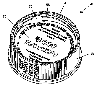
Referring to FIGS. 15 and 16, liner 70 may include a tab element 76 for
assisting
removal of the liner from the closure cavity to which the liner is inserted.
As noted
above, to easily secure the liners without glue or other adhesives, the liners
70 preferably
include a diameter that is substantially the same as the diameter of the side
wall 52 of the
closure 40. As such, it is often difficult to remove a liner from the closure
without a
sharp tool for prying the liner out of the closure. While some liners are
preferably
designed such that removal is not easy (i.e., no tab element is provided), it
is preferable in
some situations, such as providing the user with coupons, that the liners are
easily
removed. In these situations, liner 70 preferably includes the tab element 76
extending
away from the perimeter of the liner such that the liner 70 may be removed by
grasping
the tab element 76 and pulling the liner out of the closure 40.
In preferred embodiments, as shown in FIG. 16, the tab element 76 is disposed
on
the outer circumference 78 of the liner 70. Thus, when inserting the liner in
a cavity of
the closure 40, the tab element extends perpendicular from the divider and
adjacent/parallel to the interior surface 54 of the circumferential side wall
52. It should
be noted that the tab element 76 is thus disposed over the engaging structure
56, 58 when
installed in the closure 40. However, while the tab element 76 is thin and/or
flexible
enough to not conflict with operation of the engaging structure with the
complementary
engaging structure of the container. While it is not preferable because the
tab element
would interfere with the indicia printed on liner 70, the tab element 76 may
alternatively
be disposed along the interior of the liner 70 such that the tab element 76
does not
interfere with the engaging structure 56, 58.
Liners 70 having tab element 76 may be inserted in either the first section
cavity
43 or second section cavity 47. As noted above, a tab element 76 is preferably
provided
on liners that are intended to be removed such as coupons and not provided on
liners
intended to be permanently installed in the respective cavity such as liners
with dosage or
warning information. By permanent, it is meant that the liner does not have a
tab element
feature to promote easy removal of the liner 70 from the closure 40. In
preferred
Page 15
CA 02871813 2014-11-20
embodiments, liners 70 having tab elements 76 are intended to be inserted into
the first
section cavity 43 while permanent liners are intended to be inserted into the
second
section cavity 47. As described above, warning information and/or operating
instructions
are preferably molded on the appropriate side of divider of the closure 40
such that the
appropriate information is visible to a user when they remove one or more of
the liners
from the closure.
According to an alternate embodiment, the divider 50 is made of a clear
plastic or
other see-through material and the side wall 52 is preferably made from a
substantially
opaque material or matte finish. In this embodiment, the closure 40 is
preferably formed
as a unitary one piece structure using a two stage injection molding process
in which the
opaque side wall 52 resin is injected separately from the transparent divider
50. In
another embodiment, the difference in transparency between the divider 50 and
the side
wall 52 is controlled by using only a single stage injection process and
varying the
surface finish on the mold itself. Thus, the steel of the mold that forms the
divider 50
would be highly polished (yielding a clear, see-through portion) while the
steel forming
the side wall 52 would be left rough (yielding a matte, opaque finish). The
opaque side
wall 52 prevents visibility of the interface of the engaging sections to
inhibit opening by
children who might be able to see the interference if the entire cap was
transparent. In
this embodiment, liner 70 may include warning indicia on one side of the liner
70 with or
without additional information on the opposite side. As the divider 50 is see-
through or
at least partially transparent in this embodiment, one side of the liner 70 is
always visible
no matter which configuration the closure 40 is applied to the container 12.
Accordingly,
the liner 70 may be inserted into either the first section 42 or the second
section 46 such
that the side of the liner having warning indicia printed thereon is displayed
while
looking down on the closure 40 when the child resistant closure system 10 is
in the non-
child resistant mode, and the other side, preferably having the additional
information
printed thereon, is displayed when the child resistant closure system 10 is in
the child
resistant mode.
In automatic filling applications, the liners 70 are preferably printed
digitally with
variable data so that the graphics and/or message of the displayed on the
liner may be
changed rapidly during the printing process. During manufacturing of the
closures 40,
Page 16
CA 02871813 2014-11-20
the various liners 70 may then be inserted into the caps randomly or in
sequence in such a
way that boxes of closures 40 are filled having liners 70 having numerous
different
displays. In this manner, every single closure in a case ordered by a pharmacy
may
potentially have a different liner 70 with different printed information to be
directed to
the user of the closure system 10 without substantially increasing the cost
per cap. For
example, a pharmacy can order a box of 1000 closures having, up to 1000
different
advertising or prescription information messages specifically tailored to that
particular
pharmacy by providing 1000 different messages selected by the pharmacy on the
liners
70. The pharmacist may then choose which closure should be used to fill the
prescription
based on the message the pharmacist would like to provide to the patient.
The liners 70 may also be printed "on demand" by the pharmacist or provided to
the pharmacist for selectively applying to a closure when filling a
prescription. In
embodiments in which the liners are printed at the pharmacy, a pharmacy
computer
preferably includes a database of various liner graphics and information, the
graphics/information being chosen from liners 70 substantially as described
above.
When filling a prescription, the pharmacist chooses one or more of the designs
from the
database to be printed on the liners. In preferred embodiments, the liners 70
will be
printed on a label sheet also including labels having prescription information
that is
typically applied to the body 13 of the container 12. Alternatively, numerous
liners 70
containing different graphics and information are pre-printed by the
pharmacist or
provided to pharmacist by a third party. In either of these manners, the
pharmacist can
choose from a variety of different liners having various information based on
such factors
as the patient, the type of prescription, current promotions, etc., and the
pharmacist can
selectively apply liners 70 to the closure 40 when filling the prescription.
In another aspect of the closure system 10, the divider 50 is disposed between
the
first section 42 and second section 46 such that the divider 50 forms a close
fit around the
opening edge 20 and opening 22 of the container 12 whether the reversible
child resistant
closure system 10 is in the child resistant mode or the non-child resistant
mode. Further,
no part of the closure 40 traverses or extends into the opening 22 whether the
reversible
child resistant closure system 10 is in the child resistant mode or the non-
child resistant
mode. Accordingly, the present disclosure provides a one piece reversible
child resistant
Page 17
CA 02871813 2014-11-20
closure system 10 that may be used in conjunction with an induction sealing
system for
providing a tamper resistant seal to the closure system 10. In operation, a
tamper
resistant liner is inserted into one of the sections 42, 46 of the closure 40.
The closure 40
is then applied to the container 12 in the desired configuration, and the
closure system 10
is passed through an induction sealing machine for sealing the tamper
resistant liner to
the opening edge 20 of the container 12.
Referring to FIG. 17, a flow chart of an exemplary method of the present
disclosure for printing and applying custom label liners to a closure 40 is
depicted. It
should be understood that the following steps are not required to be performed
in any
particular order, and, in certain embodiments, one or more of the steps may be
omitted.
The method of FIG. 17 and each of the alternate embodiments described below
provide
for the custom printing of liners to be used on a reversible child resistant
closure system
such that the custom information of a liner is viewable to a user of the
closure system
when the closure is installed on the container in both the child resistant
mode and the
non-child resistant mode. Further, the custom information of the liner that is
viewable
when the closure is installed on the container in the child resistant mode may
be
substantially the same or different than the custom information of the liner
that is
viewable when the closure is installed on the container in the non-child
resistant
configuration.
In step 100, a pharmacy is provided and maintains a supply of reversible child
resistant closure systems 10 including a supply of closures 40 substantially
as described
above. The term pharmacy is used herein to refer to any entity that fills
pharmaceutical
prescriptions and medications into closure systems. However, it should be
understood
that similar methods could be performed by other users of the reversible child
closure
systems 10 irrespective of the contents of the container 12.
Referring to step 102, a database is maintained having a plurality of liner
designs,
each design having varying custom information. The custom information of the
liner
designs typically includes the information options substantially as described
above with
respect to the liners 70. In particular, the liner designs may include one or
more of the
following: promotional information such as company branding, advertisements,
and
coupons; prescription information such as the name of the prescribed
pharmaceutical or
Page 18
CA 02871813 2014-11-20
dosage/compliance instructions; warning information indicating the closure 40
is in the
non-child resistant configuration; and/or operating instructions for
applying/removing the
closure 40 to the container 12. The database in step 102 is preferably
accessible in a
computer system maintained by the pharmacy or maintained by a third party with
the
pharmacy having access to the third party database.
In step 104, the pharmacy selects from the database particular liner designs
to be
printed on liners. The selections are made by the pharmacy based at least in
part on the
custom information the pharmacy determines it may want to provide to users of
the
reversible child resistant closure systems 10. For example, if the pharmacy
would like
the option of providing to users of certain prescribed pharmaceuticals
information on the
closure 40 pertaining to dosage instructions (i.e., "REMINDER: TAKE 2 PILLS A
DAY"), the pharmacy will select at least one liner design having the
applicable dosage
instructions. If the pharmacy determines to provide its branding on the
closure 40 in
certain circumstances, it will select at least one liner design having the
applicable
branding.
In step 106, the selected liner designs are printed on a plurality of the
liners 70
(discussed above). Each liner includes custom information corresponding to the
custom
information of one of the liner designs selected in step 104. In certain
embodiments, the
liners are printed by the pharmacy. When the liners are printed by a third
party, the liners
are delivered to the pharmacy in step 108.
In step 110, the pharmacy selects a first liner to be inserted in the closure
from the
plurality of liners based on the custom information desired to be visible when
the closure
40 is installed on the container in the child resistant mode. In certain
embodiments,
numerous liners having many different types of custom information are provided
to the
pharmacy in step 108. As such, the pharmacist has many types of liners to
choose from
when filling a prescription. For example, the plurality of liners may include
a liner
having branding of the pharmacy displayed thereon, a coupon or advertisement
for goods
and services offered by the pharmacy, an advertisement for a company
geographically
located proximate to the pharmacy, dosage instructions relating to the
pharmaceutical
being prescribed, and the like. The pharmacist may then select from the
plurality of
Page 19
CA 02871813 2014-11-20
liners which message he would like to provide to the user of the
pharmaceutical
prescription when the closure 40 is applied to the container 12 in the child
resistant mode.
Similarly, in step 112, the pharmacy selects a second liner from the plurality
of
liners based on the custom information desired to be visible to the user of
the
pharmaceutical storage system when the closure 40 is installed on the
container in the
non-child resistant mode. In preferred embodiments, the second liner will
include
warning information indicating that the closure system is in the non-child
resistant mode.
As such the plurality of liners includes a group of liners all having such
warning
information to be inserted in the second section cavity. As shown in FIG. 12D,
this
group of liners preferably also includes additional custom information as
described
above. The custom information of the second liner may be similar to the custom
information of the first liner, or the first and second liners may have
entirely different
respective messages. For example, the first liner may include dosage
information for the
prescribed pharmaceutical while the second liner includes promotional
information such
as a QR code to be scanned. Alternatively, both the first liner and the second
liner may
include the same dosage instructions for the prescribed pharmaceutical and/or
the same
promotional information such as company branding.
In step 114, the first liner is inserted into the first section cavity and the
second
liner is inserted into the second section cavity of the closure 40. In step
116, the
pharmacy applies the closure 40 to the container 12 in one of the child
resistant mode or
the non-child resistant mode. When the closure 40 is applied to the container
12 in the
child resistant mode, the custom information of the first liner will be
displayed to the user
of the system 10. When the closure 40 is applied to the container 12 in the
non-child
resistant mode, the custom information of the second liner will be displayed
to the user of
the system 10.
In an alternate method of the disclosure where the database of liner designs
is
maintained by a third party, the pharmacy selects from the database the liner
designs to
be printed on the liners as described above in regards to steps 104 and 106.
However,
instead of the liners being delivered to the pharmacy in step 108 and the
pharmacy
inserting the liners in steps 110 and 112, the third party inserts the
selected liners into the
appropriate section cavities of a plurality of closures 40 for the pharmacy.
As described
Page 20
CA 02871813 2014-11-20
above, in automatic filling applications, the liners are preferably printed
digitally with
variable data so that the graphics and/or message of the displayed on the
liner may be
changed rapidly during the printing process. The liners may then be inserted
into the
closures randomly or in sequence in such a way that boxes of closures are
filled having
liners 70 having numerous different liner designs. The closures 40 are then
delivered to
the pharmacy with the selected liners already installed in the closures 40.
In another alternate method of the disclosure, the pharmacy prints the
selected
liner designs for the first and second liners "on demand." In other words, the
liners
having desired custom information are printed when filling a prescription as
opposed to
being selected from pre-printed liners. In this embodiment, the liner designs
may be
selected from the database and printed at the pharmacy when filling the
prescription.
Alternatively, certain liner designs from the database may be preprogrammed to
be
printed by the computer system based on the pharmaceutical prescription being
filled.
For example, when a prescription is being filled for diabetes equipment, the
computer
system may be programmed to print liners having an advertisement for diabetic
equipment or supplies. In certain embodiments, the liners are included on a
label sheet
that also includes the labels to be applied to the circumference of the
container. In other
embodiments, the liners are printed separately from the label sheets.
A particularly useful application in which the liner designs are selected and
printed on the labels "on demand" is when the pharmacy chooses to include
dosage
instructions particular to the pharmaceutical being prescribed such as the
liners shown in
FIG. 14. In this embodiment, the database includes a plurality of liner
designs having
various dosage instructions such "REMINDER: TAKE ONE PILL EVERY
MORNING," "REMINDER: TAKE 1 PILL EVERY 8 HOURS FOR PAIN," etc. When
filling a prescription, the pharmacy picks a liner design from the database
having the
appropriate dosage instructions for the pharmaceutical being prescribed. The
selected
liner design is then printed on one or both of the first and second liners at
the pharmacy.
Alternatively, the appropriate dosage instructions are automatically printed
on the liners
when filling a pharmaceutical prescription. For example, the pharmacy selects
the option
to print compliance liners when filling a prescription. The pharmacy computer
then
prints the appropriate dosage instructions on liners ticked together on a
label sheet. The
Page 21
CA 02871813 2014-11-20
pharmacist then removes the printed liners and inserts them into the first and
second
section cavity of the closure.
In yet another method of the disclosure, the liners may be printed with a
first
selected liner design on a first side of the liner and a second liner design
on the second
side of the liner. Such a liner having custom information printed on both
sides may be
used in embodiments of the closure 40 having a transparent center divider 50
as described
above.
The foregoing description of preferred embodiments for this disclosure has
been
presented for purposes of illustration and description. It is not intended to
be exhaustive
to or to limit the disclosure to the precise form disclosed. Obvious
modifications or
variations are possible in light of the above teachings. The embodiments are
chosen and
described in an effort to provide the best illustrations of the principles of
the disclosure
and its practical application, and to thereby enable one of ordinary skill in
the art to
utilize the disclosure in various embodiments and with various modifications
as are suited
to the particular use contemplated. All such modifications and variations are
within the
scope of the disclosure as determined by the appended claims when interpreted
in
accordance with the breadth to which they are fairly, legally, and equitably
entitled.
Page 22