Note: Descriptions are shown in the official language in which they were submitted.
CA 02872418 2014-11-26
Processing system for powders, and method for processing
powders
The invention relates to a processing system for in
particular pharmaceutical powders of the generic type stated
in the preamble of claim 1, and to a method for processing
such powders and for decontaminating the processing system.
In the pharmaceutical industry to some extent powders
which are highly effective are processed in that they are
filled into hard gelatine capsules or pressed to tablet form,
for example. In a corresponding concentration such highly
effective powders may have a toxic effect. Therefore, it has
to be ensured in the processing of such powders that the
machine operator and the environment are not overly exposed
or even endangered.
According to the prior art, such powders are
processed either in isolated rooms and/or by machine
CA 02872418 2014-11-26
- 2 -
JACKISCH & PARTNERS
operators who are equipped with special protective gear. The
effort for personal protection, for example in the form of
full protective clothing, and for isolating the machines, for
example in the form of a tightly sealed housing for
accommodating the processing device, is large and cost-
intensive. Freedom of movement of the machine operator and
access to the processing device are significantly restricted.
Particularly problematic is the contamination of the
interior space of the closed housing and of the machine parts
disposed therein by unavoidable pulverulent residues. After
the completion of a production cycle and prior to accessing
the interior space of the housing, intensive cleaning is
required to remove pulverulent residues. To this end, the
prior art provides intensive rinsing with water with the
optional addition of cleaning agents. The rinsing water
running off is tested for pulverulent component parts. It is
only when a sufficiently low concentration has been
established that the housing door may be opened for access to
the processing device which is disposed in the interior space
of the housing. Such a process is described as "washing in
place" (WiP). In a complementary manner to the intensive
rinsing with water in the case of the WiP method, foam which
is sprayed on and which creeps into hard-to-reach corners
and, on account thereof, facilitates the release and rinsing
off of pulverulent residues may also be employed.
The WiP method requires specially designed machines
CA 02872418 2014-11-26
- 3 -
JACKISCH & PARTNERS
having housings which are correspondingly closed. Both
machine and housing have to be absolutely tight, in
particular in relation to the rinsing water being employed,
so that no contaminated rinsing water may leak. Given the
multiplicity of the moving parts, this is difficult to
implement, since not only the housing including its door but
also the moving parts of the processing device, such as shaft
bearings, actuation ducts or the like have to be reliably
sealed. The employment of standard machines is thus excluded.
Adapting the processing device to changing production
requirements is difficult and complex. Production is
inflexible at high operational costs. Apart from the high
investment costs, high disposal costs for the rinsing water
arise too.
It is in particular problematic that individual
converting stations within a processing device have an
increased frequency of disturbance. For example, in the case
of capsule-filling machines, jamming or similar, which inter
alia is due to dimensional variations and/or defects in the
supplied empty capsules, arises frequently at that station
through which empty capsules are supplied. However, such a
malfunction or a similar one, which in principle is very easy
to rectify, can only be inadequately managed under the
restrictive use conditions pertaining to an intervention
while wearing a glove or other protective measures. There is
demand for a simple and uncomplicated possibility of access
CA 02872418 2014-11-26
- 4 -
JACKISCH & PARTNERS
in order to rapidly rectify disturbances, while observing the
requirements of operator safety.
The invention is based on the object of stating a
processing system for in particular pharmaceutical powders,
which is cost-effective, is flexible in the production
process, and is easy to manage without endangering humans and
the environment.
This object is achieved by a processing system having
the features of claim 1.
The invention is furthermore based on the object of
stating a method for processing in particular pharmaceutical
powders by means of a processing system which can be carried
out easily and with low complexity, while maintaining the
protection of humans and the environment.
This object is achieved by a method having the
features of claim 9.
The invention is first of all based on the finding
that processing systems in which the processing device
displays a plurality of converting stations which are
employed in a cyclical manner can be divided into various
zones having different loadings of dust or contamination,
respectively. The processing system displays at least one
first zone and one second zone, wherein each zone is in each
case assigned at least one converting station of the
processing device. The first zone here is meant to be that
zone which, due to operational reasons, has the lowest
CA 02872418 2014-11-26
,
. .
, - 5 -
JACKISCH & PARTNERS
individual incidence of dust or contamination, respectively,
and which may be accessed by an operator even without
particular protective measures as long as an introduction of
dust or contamination, respectively, from the adjacent second
zone, which is loaded to a higher extent, can be avoided.
Proceeding therefrom, it is provided according to the
invention that a cleaning tunnel which transgresses at least
one converting station of the second zone is disposed in the
second zone, which, due to operational reasons, has a higher
incidence of dust or contamination, respectively. A first end
of the cleaning tunnel adjoins the first zone, wherein a
suction installation is disposed in the region of an opposite
second end of the cleaning tunnel. In a corresponding
operating method, by means of the suction installation, a
purifying-gas stream is generated in the cleaning tunnel. A
technical gas may be employed for the purifying-gas stream.
The purifying-gas stream is preferably a purifying-air
stream.
The purifying-air stream being configured in the
cleaning tunnel raises dust and other contaminations in the
region of the converting stations disposed there, wherein,
however, as a result of the protective effect of the cleaning
tunnel, said dust and contaminations cannot be distributed
throughout the entire processing system. Rather, the
particles raised initially remain within the purifying
tunnel, are carried away by the purifying-air stream and are
CA 02872418 2014-11-26
- 6 -
JACKISCH & PARTNERS
removed at the end of the cleaning tunnel by means of the
suction installation. On account of the duct effect of the
cleaning tunnel, effective particle removal is possible in
such a manner that in certain circumstances more intensive
cleaning measures, such as "washing in place" (WiP), may even
be dispensed with.
However, it is in particular a carryover of particles
from the more highly loaded second zone into the less loaded
first zone that is avoided. This is supported in particular
by the suction installation being disposed at that end of the
cleaning tunnel which is opposite to the end which adjoins
the first zone. The purifying-gas stream or the purifying-air
stream, respectively, thus points away from the first, less
loaded zone, whereby particles cannot make their way counter
to this gas stream into the first zone. Access to the
individually less loaded first zone by the operating
personnel is thus possible without further protective
measures in particular when the suction installation is
running. By dispensing with interventions while wearing a
glove or other protective measures, rectifying disturbances
or other interventions at the converting stations of the
first zone is/are readily possible.
In one preferred embodiment, the processing device
displays a conveying means having one direction of movement.
In particular, such a conveying means is a turntable, but may
also be an oval conveyor or a revolving conveyor belt by way
CA 02872418 2014-11-26
- 7 -
JACKISCH & PARTNERS
of which, for example, a capsule holder or other target
containers, such as blister packs or similar, for the purpose
of a metering and filling process are cyclically displaced
from one converting station to another. The suction
installation here is advantageously disposed on the second
end of the cleaning tunnel which lies opposite the direction
of movement. During operation, the purifying-gas stream here
runs counter to the direction of movement of the conveying
means. On account of the counter movement mentioned, it is
ensured that the elements moved by the conveying means, such
as container receptacles or capsule receptacles,
respectively, or similar, are purified in the cleaning tunnel
and subsequently also maintain their purified state until
they make their way into the less loaded first zone.
Carryover of particles from the second zone into the first
zone is thus reliably avoided.
In an expedient refinement of the invention at least
one blower nozzle which is directed into the cleaning tunnel
and toward the suction installation is provided. By means of
this at least one blower nozzle, a directed blowing stream
having a directional component in the direction of the
purifying-gas stream is generated. It may be expedient for
one or more such blower nozzles to be disposed, for example,
outside the cleaning tunnel and here to be directed into that
end of the cleaning tunnel which, when viewed in the
direction of _flow, is on the entry side. However, it is in
CA 02872418 2014-11-26
- 8 -
JACKISCH & PARTNERS
particular an arrangement of the blower nozzles inside the
cleaning tunnel which is considered. A plurality of blower
nozzles which are distributed in the longitudinal direction
and/or in the circumferential direction of the cleaning
tunnel are expediently provided. By way of a suitable
orientation of the blower nozzles, particular, suitable
points of the respective converting station can be blown down
in a targeted manner. Moreover, the mentioned directional
component supports the configuration of the purifying-gas
stream in the provided direction pointing away from the first
zone.
In one advantages embodiment, at least the second
zone is enclosed by a housing, wherein first means for
generating a pressure differential between the second zone
and the first zone are provided and configured in such a
manner that, during operation, a second internal pressure
which is smaller than a pressure of the first zone prevails
in the housing of the second zone. In a continuation of this
concept according to the invention, the processing system may
optionally also display an additional third zone having at
least one assigned converting station, wherein the third zone
is enclosed by a housing. In this case, second means for
generating a pressure differential between the third zone and
the second zone are provided and configured in such a manner
that, during operation, a third internal pressure which is
smaller than the second internal pressure in the housing of
CA 02872418 2014-11-26
- 9 -
JACKISCH & PARTNERS
the second zone prevails in the housing of the third zone.
In any case, a cascade-type pressure differential
between the various zones is created, wherein the highest
pressure prevails in the surrounding region of the first
zone, and wherein, in relation thereto, the second internal
pressure is smaller. The third internal pressure of the third
zone, if the latter is present, is then even smaller. A
complete sealing of the corresponding housings may be
dispensed with here, since air from the surroundings follows
the cascade-shaped pressure differential and, by way of
inevitable defects in air tightness, gaps or similar, always
forces its way from the least loaded first zone to the more
highly loaded second zone and from there to the even more
highly loaded third zone. Dust particles or other
contaminations cannot be disseminated counter to this
pressure differential and the flows through gaps and defects
in air tightness resulting thereform, and thus cannot make
their way into the first zone. The latter is not compromised
by the high load of contaminations of the second or third
zone, respectively, and may be left without particular
protective measures. Of course, it is possible for also the
first zone to be provided with its own housing, wherein a
pressure differential in relation to the atmospheric external
pressure is generated by way of a reduced first internal
pressure here too. In particular, however, the pressure in
the surrounding region of the first zone is equal to the
CA 02872418 2014-11-26
=
- 10 - JACKISCH & PARTNERS
atmospheric external pressure, wherein a housing for the
first zone may then optionally even be dispensed with. In any
case, however, easy access from the outside to the converting
stations of the first zone is possible.
Any constructive types, such as tablet presses or
similar, may be considered as a processing system for powders
in the sense of the invention. The processing device is, in
particular, a capsule-filling installation, wherein at least
one converting station of the first zone is an empty-capsule
supply station, wherein at least one converting station of
the second zone is a capsule-closing station and/or a
capsule-ejecting station, and wherein in particular one
converting station of the third zone is a powder-metering
station and/or powder-filling station. It is here that the
advantages of the invention come to bear in particular.
Naturally, the highest degree of contamination which can be
kept apart from the lesser degree of contamination in the
region of the capsule-closing station or the capsule-ejecting
station, respectively, of the second zone prevails in the
powder-metering station and/or in the powder-filling station.
Individually, the empty-capsule supply station of the first
zone displays the lowest incidence of contamination, on the
one hand, while the highest requirement for occasional manual
intervention exists here, on the other hand. In conjunction
with the cleaning tunnel according to the invention and in
particular the pressure cascade mentioned above, simple
CA 02872418 2014-11-26
=
- 11 - JACKISCH & PARTNERS
intervention without particular protective measures is
possible.
In one preferred optional embodiment, the processing
system comprises at least one first system part and at least
one second system part, wherein the processing device for the
powder is divided into at least one first device part and at
least one second device part. The first zone, mentioned
above, is assigned to the first system part, while the second
zone and, in particular, also the third zone are assigned to
the second system part. The first and the second system parr
in each case display one closed housing having an outer side
and having in each case one first or second, respectively,
interior space, wherein the first device part is disposed in
the interior space of the first housing, and the second
device part is disposed in the interior space of the second
housing. The first system part is conceived so as to be
stationary, while the second system part is configured so as
to be mobile. The second system part is coupleable to the
first system part and decouplable therefrom by means of a
lock. In a corresponding method step, the second system part
is decoupled from the first system part and, with the lock
closed, is forwarded to a separate cleaning operation. As a
consequence of the construction manner which, on account
thereof, is modular and partly mobile, the first system part
having the slightly contaminated first zone may remain in
place, wherein after decoupling of the second, mobile system
CA 02872418 2014-11-26
- 12 -
JACKISCH & PARTNERS
part, maintenance works or conversion works, for example, may
be performed without a comparatively large cleaning and
protective effort on the first stationary system part. The
decoupled second system part having the more highly
contaminated second and third zones may be transported
without risk when the lock is closed and may be subjected to
intensive cleaning, for example by way of washing, at a
suitable point, without activities on the first system part
being compromised on account thereof.
Exemplary embodiments of the invention are described
in more detail below by means of the drawing, in which:
Fig. 1 in a schematic plan view, shows the in-principle
construction of a processing system according to the
invention, having various zones, converting stations,
and a cleaning tunnel;
Fig. 2 in a perspective and enlarged sectional illustration,
shows the arrangement as per fig. 1 in the region of
a single converting station, with details of the
cleaning tunnel surrounding said converting station;
Fig. 3 in a schematic sectional illustration, shows the in-
principle construction of a processing system
according to the invention, having installations for
dry decontamination, in the form of suction, blowing
down, and powder binding;
Fig. 4 shows a variant of the arrangement as per fig. 3,
having one stationary and one mobile system part,
CA 02872418 2014-11-26
- 13 -
aT,cKIscH & PARTNERS
wherein the installations for dry decontamination are
provided for the stationary system part;
Fig. 5 shows the arrangement as per fig. 4, having system
parts, which have been decoupled from one another,
for dry decontamination of the stationary system
part, and separate decontamination of the mobile
system part.
Fig. 1, in a schematic plan view, shows the in-
principle construction of a processing system 1, according to
the invention, for in particular pharmaceutical powders. The
term "powder" in the sense of the invention does not only
mean fine-grained dry substances, but also comprises
granular-type materials and other materials in the processing
of which powder-type dust may be set free. The processing
system 1 shown in an exemplary manner is provided for
processing highly effective pharmaceutical powders having
high concentrations of active ingredients, wherein such a
highly effective powder in corresponding doses may be
incompatible or even toxic. In order to protect the operator
of the processing system 1 and the environment from such
undesirable effects, the design according to the invention of
the processing system 1 and the method which, in conjunction
therewith, will be described in more detail are provided.
The processing system 1 comprises a housing 2 and a
processing device 5 disposed therein for the powder. The
processing device 5 comprises a plurality of converting
CA 02872418 2014-11-26
- 14 -
JACKISCH & PAPTNERS
stations 41, 42, but at least two, which are employed in a
cyclical manner, wherein space has been made in the exemplary
embodiment shown for a total of nine converting stations 41,
42, 43. The processing system 1 is divided into at least one
first zone I and one second zone II, and here also optionally
even into a third zone III. The first zone I is assigned at
least one converting station 41, while the second zone II is
assigned at least one further converting station 42. The
optional third zone III is also assigned at least one
dedicated converting station 43. The housing II, on the inner
side, is provided with separation walls 58, 59, 60, such that
interior spaces which are separate from one another are
created while individual housings 51, 52, 53 are formed. The
housing 51, which is provided only in an optional manner,
encloses the first zone I, while the further second housing
52 encloses the second zone II. Finally, the optional third
zone III is also enclosed by a third housing 53.
The processing device 5 shown may be a tablet press,
a filling station for blister packs, or any other processing
device for powders. In the exemplary embodiment shown, the
processing device 5 is a capsule-filling device in which a
converting station 41 of the first zone I is an empty-capsule
supply station. One of the converting stations 42 of the
second zone II is a capsule-closing station, while a further
converting station 42 of the second zone II, according to the
schematic illustration as per fig. 2, is a capsule-ejecting
CA 02872418 2014-11-26
- 15 -
JACKISCH & PARTNERS
station. The converting station 43 of the third zone III is a
powder-metering station and powder-filling station in which
empty lower parts of capsules are filled with powder. Beyond
this, further converting stations not described in more
detail here may still be provided in all zones I, II, III.
The processing device 5 displays, for example, a
conveying means for the target container which is to be
filled with the powder, by way of which the individual
converting stations 41, 42, 43 are cyclically visited in the
direction of movement 49 which is indicated by an arrow. In
the exemplary embodiment shown, the conveying means is a
turntable 48, but may also be an oval conveyor or a revolving
conveyor belt or a revolving conveyor chain, respectively.
Corresponding to the maximum possible number of, in the
present case, an exemplary nine converting stations 41, 42,
43, here a total of nine retaining devices for the target
containers, an exemplary nine segment carriers 57 for
capsules, are fastened on the turntable 48 and, conjointly
therewith, moved in a direction of movement 49 which is
indicated by an arrow.
Corresponding to the illustration as per fig. 1, a
cleaning tunnel 44 having a first end 45 and a second end 46
is disposed in the second zone II. The first end 45 of the
cleaning tunnel 44 adjoins the first zone I, while the
opposite second end 46, in relation to the longitudinal
direction of the cleaning tunnel 44, points away from the
CA 02872418 2014-11-26
- 16 -
JACKISCH & PARTNERS
first zone I. A suction installation 6 by means of which the
interior space of the cleaning tunnel 44 is suctioned off
during operation is disposed in the region of the second end
46. The cleaning tunnel 44 transgresses at least one
converting station 42 of the second zone II, here all
converting stations 42 which, counter to the direction of
movement 49 of the turntable 48, lie between the first zone I
and the third zone III. During operation, by means of the
suction installation 6, a purifying-gas stream 56, here a
purifying-air stream, is generated in the cleaning tunnel 44,
in that air which is slightly loaded or not at all loaded is
suctioned in from the first zone I through the first end 45,
is guided on the inner side of the cleaning tunnel 44, and is
suctioned off in the region of the second end 46. It can also
be obtained from the illustration according to fig. 1 that
the second end 46 having the suction installation 6 disposed
thereon lies in the direction of flow through the cleaning
tunnel 44, counter to the direction of movement 49 of the
turntable 48, downstream of which the purifying-gas stream 56
runs counter to the direction of movement 49 of the conveying
means or of the turntable 48, respectively.
It can be moreover obtained from the illustration as
per fig. 1 that first means 54 for generating a first
pressure differential between the second zone II and the
first zone I are provided as part of the processing system 1,
wherein these means are embodied as a pump in the exemplary
CA 02872418 2014-11-26
- 17 -
JACKISCH & PARTNERS
embodiment shown. In an analogous manner thereto, second
means 55 for generating a second pressure differential
between the third zone III and the second zone II are also
optionally provided. The first means 54 for generating the
pressure differential are configured and also utilized during
operation in such a manner that an internal pressure p2 which
is smaller than a pressure pl in the first zone I is
established in the housing 52 of the second zone II. In turn,
the pressure pi, by suitable means, may be smaller than the
atmospheric external pressure pa. Preferably, the pressure p1
in the surrounding region of the first zone I is equal to the
atmospheric external pressure pa. The second means 55 for
generating the pressure differential are configured and also
utilized during operation in such a manner that a third
internal pressure p3 which is smaller than the second
internal pressure p2 in the housing 52 of the second zone II
is established in the housing 53 of the third zone III.
Overall, a descending pressure cascade having p3<p2<p1<pa can
be adjusted in this way.
Fig. 2, in a perspective and enlarged sectional
illustration, shows the arrangement as per fig. 1, in the
region of one of its second converting stations 42 of the
second zone II, with details of the cleaning tunnel 44
surrounding the former. The cleaning tunnel 44 displays a
substantially closed cross section which is formed by the
base of the processing system 1, by side walls and by a
CA 02872418 2014-11-26
- 18 -
JACKISCH & PARTNERS
cover. The closed cross section is interrupted in a merely
minor manner only there where the turntable 48 extends into
the interior space of the cleaning tunnel 44. However,
according to the invention, such and other comparatively
small interruptions of the otherwise closed tunnel cross
section are to be contained such that the aforementioned
cleaning stream 56 within the cleaning tunnel 44 is
established with gas exchange in relation to the outer side
of the cleaning tunnel 44 being negligible with respect to
the cleaning effect.
It can also be obtained from the illustration as per
fig. 2 that at least one blower nozzle 50, here a plurality
of blower nozzles 50, is disposed in a complementary manner
to the suction installation 6 as per fig. 1. The blower
nozzles 50 with their blowing stream are directed onto points
to be blown clean of the adjacent converting station 42, on
the one hand, and into the cleaning tunnel 44 and toward the
suction installation 6, on the other hand. During operation,
in each case a blowing stream 57 is created having a
directional component in the direction of the purifying-gas
stream 56, on account of which, apart from the cleaning
effect, also support of the purifying-gas stream 56 arises.
Corresponding to the illustration as per fig. 2, a
plurality of blower nozzles 50, here an exemplary six, are
distributed in the circumferential direction of the cross
section of the cleaning tunnel 44. Alternatively or
CA 02872418 2014-11-26
- 19 -
JACKISCH & PARTNERS
additionally, corresponding to the illustration as per fig.
1, also a plurality of blower nozzles 50 are distributed in
the longitudinal direction of the cleaning tunnel 44 and are
in each case assigned to one converting station 42.
In the exemplary embodiment as per figs. 1 and 2 the
cleaning tunnel 44 is shown and described interacting with
the separation walls 58, 59, 60 and means 54, 55 in order to
generate pressure differentials or pressure cascades,
respectively. The cleaning tunnel 44 according to the
invention may however also be employed without such
supporting means in a processing system 1 in the interior
space of which a uniform pressure prevails without pressure
differentials, wherein this internal pressure may also be
equal to the atmospheric surrounding pressure pa. It is in
any case achieved that the first zone I is kept free from
contaminating particle carryovers from the second zone II
and/or the third zone III. The level of contamination in the
first zone I can be kept so low that, if and when required,
thereto or to the converting stations 41 disposed thereon,
respectively, is possible without particular measures for
operator safety.
Figs. 3 to 5 show even further exemplary embodiments
of processing systems 1 for powders, having details which are
substantial to the invention and which may be individually
employed as shown and described in the following but, in
particular, also be employed in any combination with the
CA 02872418 2014-11-26
- 20 -
JACKISCH & PARTNERS
arrangement as per figs. 1 and 2. It may be expedient, in
particular, for the processing system 1 as per figs. 1 and 2
to comprise at least one first system part 31 and at least
one second system part 32, corresponding to the exemplary
embodiment as per figs. 4 and 5 which is described further
below, wherein the processing device 5 for the powder is
divided into at least one first device part 33 and at least
one second device part 34. Corresponding to the comparative
viewing of figs. 1, 2, 4, and 5, the first zone I here is
then assigned to the first system part 31, and the second
zone II and, in particular, also the third zone III are
assigned to the second system part 32. Here, the first and
the second system part 31, 32 in each case display one closed
housing 2, 35 having an outer side 3 and having in each case
one first or second, respectively, interior space 4, 36,
wherein the first device part 33 is disposed in the interior
space 4 of the first housing 2, and the second device part 34
is disposed in the interior space 36 of the second housing
35. The first system part 31 is conceived so as to be
stationary. The second system part 32 is configured so as to
be mobile. The second system part 32 is coupleable to the
first system part 31 and decouplable therefrom by means of a
lock 37, as is described in more detail further below in the
context of figs. 4 and 5. In a corresponding method step, the
second system part 32 is decoupled from the first system part
31 and, with the lock 37 closed, is forwarded to a separate
CA 02872418 2014-11-26
- 21 -
JACKISCH & PARTNERS
cleaning operation in the case of cleaning and/or maintenance
or conversion requirements, respectively.
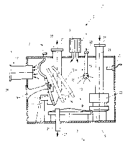
Fig. 3, in a schematic sectional illustration, shows
a further exemplary embodiment of a processing system 1 for
powders, according to the invention. The processing system 1
comprises a closed housing 2 having an outer side 3 and an
interior space 4, and a processing device 5 for the powder,
which is disposed in the interior space 4 of the housing 2.
The housing 2 is closed in the sense that during processing
operations no immediate access from the outside to the
processing device 5 is possible. However, the housing 2 is
not completely sealed against entry of air, water or similar.
In particular, the processing device 5 also does not display
any particular sealing measures on its moving parts against
the entry of air or water or similar, so that any
standardized processing device 5 may be employed. In the
exemplary embodiment shown, the processing device 5 is a
capsule-filling installation having a metering station 25 by
means of which powder is metered and filled into capsules.
However, a tablet press or the like may also be provided.
In detail, besides the metering station 25 the
capsule-filling installation comprises an empty-capsule
supply 20, a powder supply 23 and a capsule outlet 26 for
completely filled and closed capsules. The empty-capsule
supply 20 and the powder supply 23 lead from the outer side 3
into the interior space 4 and, on the outer side 3, are
CA 02872418 2014-11-26
- 22 -
JACKISCH & PARTNERS
provided with couplings 21, 24. The capsule outlet 26 is led
from the interior space 4 through the wall of the housing 2
to the outer side 3, and on the outer side 3 displays an
interface 27. The couplings 21, 24 and the interface 27 are
designed in such a manner that material may indeed be guided
therethrough, however without powder which has been set free
during operation being able to reach the outer side 3 from
the interior space 4.
Moreover, the processing system 1 is equipped with an
installation for dry decontamination and, to this end,
comprises a suction installation 6 for the interior space 4,
and a compressed-air rinsing installation 7. Moreover, a
controlled air supply 8 having an air filter 9, a spraying
installation 12 for a powder-binding agent 13, a particle
sensor 10 for monitoring the interior space for powder
residues, and a gloved intervention element 18 are provided
for dry decontamination.
The compressed-air rinsing installation 7 may
comprise an arrangement of stationary compressed-air nozzles,
and in the exemplary embodiment shown display a manually
guided air-rinsing nozzle 11 which is disposed in the
interior space 4 and which is provided by means of a supply
hose and via a coupling 19 lying on the outside with
compressed air. Besides a binding-agent spray head 15, having
an associated coupling 22, which is fastened in a stationary
manner in the housing 2, the spraying installation 12 also
CA 02872418 2014-11-26
- 23 -
JACKISCH & PARTNERS
comprises a manually guided binding-agent spraying nozzle 14
disposed in the interior space 4. The suction installation 6
comprises a stationary suction 17, having an interface 28
which lies on the outside, which is led through the wall of
the housing 2, and optionally also a manually guided suction
nozzle 16 which is disposed in the interior space 4. The same
as has been described further above in the context of the
couplings 19, 24 and the interface 27 applies to the design
of the couplings 19, 22 and the interface 28. By means of the
gloved intervention element 18, the machine operator standing
on the outer side 3 has access to the air-rinsing nozzle 11,
the binding-agent spraying nozzle 14 and/or the suction
nozzle 16. Since also the binding-agent spraying nozzle 14 or
the suction nozzle 16, respectively, are supplied by
corresponding hose lines (not illustrated) leading to the
outside in a manner which is comparable to the air-rinsing
nozzle 11, the machine operator can grip the mentioned
nozzles and guide them to any point, including all individual
parts of the processing device 5, in the interior space 4.
During operation or in the operational method
according to the invention, respectively, the powder is
processed by means of the processing device 5 which is
disposed in the interior space 4 of the housing 2. In an
exemplary manner, this is carried out in that empty capsules
are supplied by way of the empty-capsule supply 20, are
filled with powder in the metering station 25, and, in the
CA 02872418 2014-11-26
- 24 -
JACKISCH & PARTNERS
filled and closed state, are discharged by way of the capsule
outlet 26. During processing, an internal pressure pi which
is smaller than an external pressure pa on the outer side 3
of the housing is maintained in the interior space 4 by means
of the suction installation 6, namely by means of the
stationary suction 17. The external pressure pa is usually
the atmospheric ambient pressure. As a result of the pressure
differential being created, air is suctioned in from the
outer side 3 into the interior space 4 via defects in the air
tightness present in the housing 2, subsequent to which, on
account of the mentioned defects in the air tightness, no
powder can make its way counter to the air stream being
created, from the interior space 4 to the outer side 3. In
addition to the leakage air stream entering as a result of
the mentioned defects in the air tightness, filtered air is
led into the interior space 4 by way of the controlled air
supply 8, subsequent to which a specific internal pressure pi
or a specific pressure differential, respectively, in
relation to the external pressure pa can be adjusted and
maintained.
For maintenance, conversion and adaptation works, in
particular on the processing device 5, decontamination of the
interior space 4 including the processing device 5 or parts
thereof, respectively, disposed therein, by way of removal of
present powder residues is required after the conclusion of
the processing of a powder. For such a decontamination
CA 02872418 2014-11-26
-25 -
JACKISCH & PARTNERS
operation, the conveying performance of the suction
installation 6 is greater than the conveying performance of
the compressed-air rinsing installation 7 in such a manner
that during rinsing of the interior space 4 including the
processing device disposed therein by means of the
compressed-air rinsing installation 7 and during simultaneous
operation of the suction installation 6, the internal
pressure pi remains smaller than the external pressure pa.
For the decontamination process, the conveying performance of
the suction installation 6 and of the compressed-air rinsing
installation 7 are thus tuned in relation to one another in
such a manner that during simultaneous operation of the
suction installation 6 and of the compressed-air rinsing
installation 7 the mentioned pressure conditions are created
or are maintained, respectively. By means of the compressed-
air rinsing installation 7, in particular by way of manual
guiding of the air-rinsing nozzle 11, adhering powder
residues are blown down from all surfaces by means of
compressed air. The raised powder residues are suctioned
together using air from the interior space 4 by means of the
suction installation 4. To this end, the stationary suction
17 may suffice. Targeted suctioning may be performed in a
complementary manner by means of the manually guided suction
nozzle 16 at specific points.
It is provided as a further method step according to
the invention that for the decontamination process, the
CA 02872418 2014-11-26
- 26 -
JACKISCH & PARTNERS
interior space 4 and the processing device 5 or parts
thereof, disposed therein are sprayed by means of the
spraying installation 12, using the powder-binding agent 13.
As a result thereof, powder residues adhering on the surfaced
and also raised powder particles on the respective surfaces
are bound, without being able to be raised again. Foam, water
vapor, a mist of water droplets and/or a gel may be employed
as powder-binding agents. Delivery of the powder-binding
agent 13 preferably takes place while an internal pressure pi
which is smaller than the external pressure pa on the outer
side 3 prevails in the interior space 4 of the housing 2.
However, in particular in the case of less critical
substances, this method step may also be performed while an
internal pressure pi which is at least approximately equal to
the external pressure pa of the outer side 3 of the housing 2
prevails in the interior space.
The process of spraying a powder-binding agent 13
described above, and thus the binding of powder residues may
be employed in combination with the combined suction-and-blow
cleaning process described at the outset. In particular,
initially suction-and-blow cleaning takes place, subsequently
followed by binding dust using the powder-binding agent 13.
However, it may also be expedient for only the binding of
powder residues using the powder-binding agent 13 to be
carried out, while dispensing with a combined suction-and-
blow cleaning.
CA 02872418 2014-11-26
- 27 -
JACKISCH & PARTNERS
The interior space 4 is monitored for freely
suspended powder particles by means of the particle sensor
10. As soon as this monitoring has determined that a
predefined limit amount of raised and suspended powder
residues has been undershot, it is to be determined as a
result that the preceding suction-and-blow cleaning and/or
the binding of free powder particles has been successful in
such a way that the negative pressure in the interior space 4
can be switched off and the housing 2 can be opened without a
risk. In the case of the binding of dust, cleaning or
removal, respectively, of the powder bound using the powder-
binding agent 13 can now be performed. The bound powder may
be wiped off. In the case of the binding using a gel, a film
having the powder residues bound therein is formed after
drying the gel, wherein the dried film can be peeled off from
the surface. Removal of the bound powder may however also be
performed already with the housing 2 closed and the pressure
differential in place, by means of the gloved intervention
element 18, for example. In any case, a signal indicating
that access to the interior space 4 is possible without risk
is generated. Maintenance, conversion and adaptation works
may be performed on the processing device 5.
Fig. 4, in a schematic sectional illustration, shows
a variant of the arrangement as per fig. 3, in which the
processing system 1 is divided into a stationary first system
part 31 and a mobile second system part 32. Additional
CA 02872418 2014-11.-26
,
- 28 - JACKISCH & PARTNERS
stationary and/or mobile system parts may be provided in a
complementary manner. The first stationary system part 31 is
conceived so as to be stationary by means of support feet 38,
and corresponding to the exemplary embodiment as per fig. 3,
displays a closed first housing 2 having a first interior
space 4. The second system part 32 is configured in the form
of a displaceable or mobile, respectively, trolley having
casters 39, and, in an analogous manner to the first system
part 31, comprises an independent, second closed housing 35
having a second interior space 36. The processing device 5
corresponds to the processing device 5 as per fig. 3, but
here is divided into a first device part 33 and a second
device part 34. The first device part 33 comprises the empty-
capsule supply 20 and the capsule outlet 26, and is disposed
in the first interior space 4 of the first housing 2. The
second device part 34 comprises the powder supply 23 and the
metering station 25, and is disposed in the second interior
space 36 of the second housing 35. In the optional case not
illustrated, additional stationary and/or mobile system parts
having a comparable construction, which in each case display
a dedicated housing and a device part of the processing
device 5 disposed in the interior space of the housing, may
be provided.
The second mobile system part 32 is embodied as an
exchangeable module and, depending on requirements, is
coupleable to the first system part 31 and also decouplable
CA 02872418 2014-11-26
- 29 - 5.7-
CKISCH & PARTNERS
therefrom by means of a lock 37. For processing the powder,
the mobile second system part 32 is coupled to the first
stationary system part 31 by means of the lock 37, according
to the illustration as per fig. 4, wherein mechanical
coupling elements (not illustrated) are present for the
accurate positioning, retaining and connecting of the second
system part 32 to the first system part 31. Here, the first
device part 33, together with the second device part 34,
forms the entire processing device 5. The first interior
space 4 and the second interior space 36 are connected to
form a common interior space by means of the opened lock 37.
Connecting of the interior spaces 4, 36, and the functional
connection of the two device parts 33, 34 takes place by way
of the opened lock 37.
The suction installation 6 having the stationary
suction 17 and the manually guided suction nozzle 16, the
compressed-air rinsing installation 7 having the manually
guided air-rinsing nozzle 11, the air supply 8 having the air
filter 9, the particle sensor 10, the rinsing installation 12
having the manually guided binding-agent spraying nozzle 14
and the stationary binding-agent spray head 15, and the
gloved intervention element 18, in embodiment and operation
correspond to the exemplary embodiment as per fig. 3, and are
disposed on the stationary first system part 31. Only the
optional particle sensor 10 is disposed in the interior space
36 of the second housing 35. Moreover, the second system part
CA 02872418 2014-11-26
- 30 -
JACKISCH & PARTNERS
32 is provided with an additional binding-agent spray head
15' as part of the spraying installation 12, and with an
additional suction 17' as part of the suction installation 6.
The processing of the powder by means of the
processing device 5 takes place as described in the context
of fig. 3, wherein an internal pressure pi which is smaller
than the external pressure pa on the outer side 3 of the
housings 2, 35 is maintained in the connected interior space
by means of the suction installation 6. Naturally, there is a
higher dust load in the mobile second system part 32, having
the powder supply 23 and the metering station 25, than in the
first system part 31, having the empty-capsule supply 20 and
the capsule outlet 26. Since the two interior spaces 4, 36
are only connected to one another by means of the lock 37,
carryover of the higher dust or powder load, respectively, in
the second interior space 36 to the first interior space 4 is
reduced to a minimum.
In preparation of a subsequent decontamination
process, the second system part 32 is decoupled from the
first system part 31, as is illustrated in fig. 5. Here, the
interior space 36 of the second housing 35 is closed off by
means of the lock 37. The associated passage on the first
interior space 4 may optionally be closed off in the same
way. On account of the closed lock 37, the second interior
space 36 of the second system part 32 is closed off in a way
that the product present therein is protected when the
CA 02872418 2014-11-26
- 31 -
JACKISCH & PARTNERS
decoupled first system part 31 is accessed. In an analogous
manner to the description of the arrangement as per fig. 3,
to this end the second housing 35 and the lock 37 do not need
to be completely air-tight and dust-tight. It may suffice for
a reduced internal pressure pi to be maintained by means of
the associated suction 17', so that no powder or dust,
respectively, might leak to the outside through any
potentially present defect of air tightness. The second
system part 32 which has been separated in this way may be
removed on its casters 39 from the first system part 31, in a
corresponding manner to an arrow 40, so that free access to
the first system part 31 is possible.
For conversion or maintenance works, and for the
remedy of faults, dry decontamination is now performed on the
free-standing first system part 31, while the second system
part 32 is decoupled. Dry decontamination of the first system
part 31 takes place by combined suctioning and blowing by
means of the suction installation 6 and the compressed-air
rinsing installation 7 and/or by way of the employment of a
powder-binding agent 13 (fig. 3) by means of the spraying
installation 12, as is described in detail in the context of
fig. 3. Upon dry decontamination having been performed, the
machine operator may access the interior space 4 and the
first device part 33, disposed therein, of the first system
part 31 without risk. Subsequently, the second system part 32
may be moved up to the first system part 31 again and be
CA 02872418 2014-11-26
- 32 -
JACKISCH & PARTNERS
coupled thereto in a corresponding manner to the illustration
as per fig. 4, on account of which the processing system 1 is
put into an operationally ready state. The processing of the
powder can be reinitiated in the way described above.
However, it is also possible for the second system
part 32, which has been decoupled as per fig. 5, to be
subjected to dedicated decontamination. To this end, dry
decontamination may be performed by employing, for example,
the binding-agent spray head 15' in the way described above.
It is likewise possible for a stand-alone compressed-air
rinsing installation (not illustrated) to be provided to this
end, besides the suction installation 6 which is in any case
present. Because of the increased degree of contamination as
compared with the first system part 31 and the poorer
accessibility of the second device part 34 under certain
circumstances, it may, however, also be expedient for the
second system part 32 to be displaced into a protected
cleaning room which is specifically provided therefor, where
the second system part 32 is subjected to intensive
decontamination, for example, employing full personal
protective gear. Instead of the standardized, not specially
sealed and thus not WiP-compatible second device part 34,
here remains also the possibility of selecting a design of
the second system part 32 which is overall WiP-compatible, on
account of which the increased contamination can be removed
by way of intensive wet decontamination.