Language selection

Search

Patent 2873221 Summary

Third-party information liability

Some of the information on this Web page has been provided by external sources. The Government of Canada is not responsible for the accuracy, reliability or currency of the information supplied by external sources. Users wishing to rely upon this information should consult directly with the source of the information. Content provided by external sources is not subject to official languages, privacy and accessibility requirements.

Claims and Abstract availability

Any discrepancies in the text and image of the Claims and Abstract are due to differing posting times. Text of the Claims and Abstract are posted:

  • At the time the application is open to public inspection;
  • At the time of issue of the patent (grant).
(12) Patent: (11) CA 2873221
(54) English Title: MOUNTING AN RFID TAG ON A SUPPORT FORMED OF A MATERIAL WHICH BLOCKS OR ATTENUATES RF SIGNALS
(54) French Title: FIXATION D'UNE ETIQUETTE D'IDENTIFICATION PAR RADIOFREQUENCE SUR UN SUPPORT FORME D'UN MATERIAU QUI BLOQUE OU ATTENUE LES SIGNAUX RF
Status: Granted and Issued
Bibliographic Data
(51) International Patent Classification (IPC):
  • G06K 19/077 (2006.01)
  • H05K 09/00 (2006.01)
(72) Inventors :
  • TALBOT, BENOIT (Canada)
(73) Owners :
  • PG SOLUTIONS INC.
(71) Applicants :
  • PG SOLUTIONS INC. (Canada)
(74) Agent: ADE & COMPANY INC.
(74) Associate agent:
(45) Issued: 2021-11-09
(22) Filed Date: 2014-12-02
(41) Open to Public Inspection: 2015-07-30
Examination requested: 2019-12-02
Availability of licence: N/A
Dedicated to the Public: N/A
(25) Language of filing: English

Patent Cooperation Treaty (PCT): No

(30) Application Priority Data:
Application No. Country/Territory Date
61933569 (United States of America) 2014-01-30

Abstracts

English Abstract

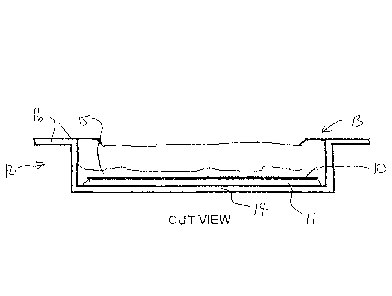
An RFID tag for attachment to a supporting material comprising a generally flat strip is adhesively mounted inside the base of a rectangular container having side walls and end walls extending generally to an open upper edge of the box where the open upper edge is arranged to be fastened to the material so that the tag thus is supported by the base at a position spaced from the material by a distance defined by a spacing of the base from the upper edge.


French Abstract

Une étiquette RFID à attacher à un matériau de support comprenant une lanière généralement plate est installée par adhésif dans la base dun contenant rectangulaire ayant des parois latérales et des parois dextrémité sétendant généralement vers un bord supérieur ouvert de la boîte, ce bord étant configuré pour être attaché au matériau, de sorte que létiquette soit supportée par la base à une position espacée du matériau par une distance définie par un espace de la base par rapport au bord supérieur.

Claims

Note: Claims are shown in the official language in which they were submitted.


7
CLAIMS:
1. An RFID tag apparatus for mounting on a material which is blocking
or attenuating to RF signals comprising:
an RFID tag in the form of a strip;
a container box for containing the tag;
the container box having a base, side walls and end walls upstanding from
the base to an open upper edge of the box;
the base being dimensioned to receive the strip forming the tag lying on the
base;
an adhesive material bonding the tag to the base;
the open upper edge being arranged to be fastened to the material;
the tag thus being supported by the base at a position spaced from the
material by a distance defined by a spacing of the base from the upper edge.
2. The apparatus according to claim 1 wherein the box is open at the
open upper edge so that the open upper edge is defined by a top edge of the
side walls
and end walls.
3. The apparatus according to claim 1 or 2 wherein the RFID tag is
affixed to the base by a wet inlay.
4. The apparatus according to any one of claims 1 to 3 wherein the
RFID tag is affixed to the base by pressure sensitive adhesive.
5. The apparatus according to any one of claims 1 to 4 wherein the tag
is covered with calking to make the tag waterproof.
Date Recue/Date Received 2021-02-19

8
6. The apparatus according to any one of claims 1 to 5 wherein the
open upper edge includes at least a pair of opposed wings for fastening to the
material.
7. The apparatus according to claim 6 wherein the opposed wings
extend outwardly from the open upper edge.
8. The apparatus according to any one of claims 1 to 7 wherein the box
is arranged to be installed using adhesive between the upper edge and the
material.
9. The apparatus according to any one of claims 1 to 7 wherein the box
is arranged to be installed using double face tape between the upper edge and
the
material.
10. The apparatus according to any one of claims 1 to 9 wherein the box
includes an opening allowing escape of moisture.
11. The apparatus according to claim 10 wherein the opening is defined
at the open upper edge.
12. The apparatus according to claim 10 wherein the opening is defined
by a recess at the open upper edge of at least one of the side and end walls.
13. The apparatus according to claim 12 wherein both side walls are
recessed so as to define a slot along the open upper edge at each side wall.
14. An article carrying an RFID tag wherein the article includes a wall
formed of a material which is blocking or attenuating to RF signals and an
apparatus
according to any one of claims 1 to 13 where the box is mounted on the wall.
Date Recue/Date Received 2021-02-19

Description

Note: Descriptions are shown in the official language in which they were submitted.


CA 02873221 2014-12-02
MOUNTING AN RFID TAG ON A SUPPORT FORMED OF A MATERIAL WHICH
BLOCKS OR ATTENUATES RF SIGNALS
This invention relates to an arrangement for mounting an RFID tag on
a support formed of a material which blocks or attenuates RF signals.
BACKGROUND OF THE INVENTION
The present invention generally relates to the tracking of containers or
other similar objects, and more particularly to apparatus and techniques for
attaching
a radio frequency identification (RFID) tag to an article where the support on
which
the tag is mounted is formed of a material which blocks or attenuates RF
signals.
There is a widespread need to track and identify a variety of items in
the normal course of business operations. For example, in a company's supply
chain, the capability to readily identify and track items can decrease the
time to
market, increase efficiency, decrease costs, and provide a host of other
advantages.
In addition in waste material collection, tracking the location of
containers using RFID tags can significantly increase the efficiency of the
system
and can provide an input to a control system which monitors and tracks the
containers which are unloaded.
One solution to such a need is an RFID tag tracking system in which
an RF1D tag is attached to each of the items to be tracked. A typical passive
RFID
tag tracking system comprises the RFID tags and an interrogator, also known as
a
reader. The RFID tag includes an antenna and a microchip, which may store data
such as a serial number or an item identification number. To read the data
stored on

CA 02873221 2014-12-02
2
the microchip, the interrogator transmits electromagnetic radio frequency (RF)
waves to the RFID tag. The antenna of the RFID tag receives these broadcast
electromagnetic RF waves and the small electrical current induced in the
antenna is
used to power the microchip. The RFID tag is powered by the received RF waves
allowing it to send data, such as the serial number, to the interrogator
through RF
waves.
Unlike a bar code read by an optical scanner, an RFD tag tracking
system does not depend upon an unobstructed line of sight from the reader to
the
item to be read since RF signals pass through many types of materials.
However,
RF signals can be blocked or interfered with by some types of materials, such
as
metals and liquids. These materials, which may be used to construct the
article to be
tracked, may prevent reliable communication between the interrogator and the
RFID
tag attached to a side of the package by blocking or substantially
attenuating.
Therefore, it would be advantageous to provide systems and methods
for attaching an RFID tag to an article which allows the RFID tag to be read
when
the article contains or is manufactured from an RF blocking, or attenuating
material.
That is, standard UHF RFID tags cannot be read when mounted directly on metal
or
any other dense material.
Some manufacturers have invented multi layers RFD tags that include
a reflective layer separated from the antenna layer by a dielectric with a
known
impedance. These tags have the disadvantage of being expensive.

CA 02873221 2014-12-02
3
SUMMARY OF THE INVENTION
According to the invention there is provided an RFID tag apparatus for
mounting on a material which is blocking or attenuating to RF signals
comprising:
an RFID tag in the form of a generally flat strip;
a container box for containing the tag;
the container box having a base, side walls and end walls extending
generally at a right angle to the base to an open upper edge of the box;
the base being dimensioned to receive the flat strip forming the tag
lying flat on the base;
an adhesive material bonding the tag to the base;
the open upper edge being arranged to be fastened to the material;
the tag thus being supported by the base at a position spaced from the
material by a distance defined by a spacing of the base from the upper edge.
Preferably the box is open at the open upper edge so that the open
upper edge is defined by a top edge of the side walls and end walls.
Preferably the RFID tag is affixed to the base by a wet inlay.
Preferably the RFID tag is affixed to the base by pressure sensitive
adhesive.
Preferably the tag is covered with calking to make the tag waterproof.
Preferably the open upper edge includes at least a pair of opposed
wings for fastening to the material.

CA 02873221 2014-12-02
4
Preferably the opposed wings extend outwardly from the open upper
edge.
Preferably each wing has a hole that will be used to install the tag on
the steel (or dense) surface by using rivets or screws.
Preferably the box is arranged to be installed using adhesive between
the upper edge and the material.
Preferably the box is arranged to be installed using double face tape
between the upper edge and the material.
Preferably the box includes an opening allowing escape of moisture.
Preferably the opening is defined at the upper edge.
Preferably the opening is defined by a recess at the upper edge of at
least one of the side and end walls.
Preferably both side walls are recessed so as to define a slot along the
upper edge of each side wall.
Preferably the article includes a wall farmed of a material which is
blocking or attenuating to RF signals and an apparatus according to any
preceding
claim where the box is mounted on the wall.
Thus the present invention provides a tag that works very well on metal
or other dense surfaces. This tag is made of standard pressure sensitive
inlays
(called wet inlays) mounted in a special plastic box. These inlays as well as
the
plastic boxes are inexpensive. This invention is based on the fact that the
reading
distance increase logarithmically with the distance separating the inlay from
the

CA 02873221 2014-12-02
dense surface. By creating a gap of 1 or 2 centimeters, the reading distance
goes
from Om to 5m.
BRIEF DESCRIPTION OF THE DRAWINGS
One embodiment of the invention will now be described in conjunction
5 with the accompanying drawings in which:
Figure 1 is a cross-sectional view through a door, door lock and
security device according to the present invention.
Figure 2 is an exploded view of the components of Figure 1
In the drawings like characters of reference indicate corresponding
parts in the different figures.
DETAILED DESCRIPTION
As shown in the Figures, a standard UHF RFID wet inlay or pressure
sensitive (label type) RFID tag 10 is attached by adhesive layer 11 such as a
weet
inlay or pressure sensitive adhesive on the bottom face of a box 12. The box
has
one end 13 open which is opposed to the surface or base 14 where the inlay
including the tag and adhesive layer is applied. Some caulking 15 partly or
wholly
filling the box can be used to make the tag waterproof. The box has a wing 16
on
each side of the open end 13 attached to the top edge of one of the end walls
17.
Each wing 16 has a hole 16A that will be used to install the tag 10 on the
steel (or
dense) surface 20 by using rivets or screws. The box can also be installed
using
some type of glue or double face tape applied on the top edge of the open end
at the
to edge of the end walls 17 and side walls 18.

CA 02873221 2014-12-02
6
The box includes an opening allowing escape of moisture where the
opening is defined at the upper edge and the opening is defined by a recess 19
at or
along the upper edge of at least one and preferably both of the side walls 18
so that
the moisture can depart the box when the box is in different orientations such
as with
the base at the top or the base vertical.

Representative Drawing
A single figure which represents the drawing illustrating the invention.
Administrative Status

2024-08-01:As part of the Next Generation Patents (NGP) transition, the Canadian Patents Database (CPD) now contains a more detailed Event History, which replicates the Event Log of our new back-office solution.

Please note that "Inactive:" events refers to events no longer in use in our new back-office solution.

For a clearer understanding of the status of the application/patent presented on this page, the site Disclaimer , as well as the definitions for Patent , Event History , Maintenance Fee  and Payment History  should be consulted.

Event History

Description Date
Letter Sent 2021-11-09
Inactive: Grant downloaded 2021-11-09
Grant by Issuance 2021-11-09
Inactive: Cover page published 2021-11-08
Pre-grant 2021-09-20
Inactive: Final fee received 2021-09-20
Notice of Allowance is Issued 2021-09-09
Letter Sent 2021-09-09
Notice of Allowance is Issued 2021-09-09
Inactive: Approved for allowance (AFA) 2021-07-28
Inactive: QS passed 2021-07-28
Inactive: Recording certificate (Transfer) 2021-03-18
Inactive: Single transfer 2021-03-04
Amendment Received - Response to Examiner's Requisition 2021-02-19
Amendment Received - Voluntary Amendment 2021-02-19
Examiner's Report 2021-02-11
Inactive: Report - QC failed - Minor 2021-02-10
Common Representative Appointed 2020-11-07
Letter Sent 2019-12-09
Request for Examination Requirements Determined Compliant 2019-12-02
All Requirements for Examination Determined Compliant 2019-12-02
Request for Examination Received 2019-12-02
Common Representative Appointed 2019-10-30
Inactive: Cover page published 2015-08-10
Application Published (Open to Public Inspection) 2015-07-30
Inactive: IPC assigned 2014-12-11
Inactive: First IPC assigned 2014-12-11
Inactive: IPC removed 2014-12-11
Inactive: IPC assigned 2014-12-11
Inactive: Filing certificate - No RFE (bilingual) 2014-12-08
Application Received - Regular National 2014-12-08
Inactive: QC images - Scanning 2014-12-02
Small Entity Declaration Determined Compliant 2014-12-02
Inactive: Pre-classification 2014-12-02

Abandonment History

There is no abandonment history.

Maintenance Fee

The last payment was received on 2020-09-28

Note : If the full payment has not been received on or before the date indicated, a further fee may be required which may be one of the following

  • the reinstatement fee;
  • the late payment fee; or
  • additional fee to reverse deemed expiry.

Patent fees are adjusted on the 1st of January every year. The amounts above are the current amounts if received by December 31 of the current year.
Please refer to the CIPO Patent Fees web page to see all current fee amounts.

Fee History

Fee Type Anniversary Year Due Date Paid Date
Application fee - small 2014-12-02
MF (application, 2nd anniv.) - small 02 2016-12-02 2016-11-09
MF (application, 3rd anniv.) - small 03 2017-12-04 2017-11-03
MF (application, 4th anniv.) - small 04 2018-12-03 2018-09-19
MF (application, 5th anniv.) - small 05 2019-12-02 2019-11-20
Request for examination - small 2019-12-02 2019-12-02
MF (application, 6th anniv.) - small 06 2020-12-02 2020-09-28
Registration of a document 2021-03-04 2021-03-04
Final fee - small 2022-01-10 2021-09-20
MF (patent, 7th anniv.) - small 2021-12-02 2021-12-02
MF (patent, 8th anniv.) - small 2022-12-02 2022-09-09
MF (patent, 9th anniv.) - small 2023-12-04 2023-11-29
Owners on Record

Note: Records showing the ownership history in alphabetical order.

Current Owners on Record
PG SOLUTIONS INC.
Past Owners on Record
BENOIT TALBOT
Past Owners that do not appear in the "Owners on Record" listing will appear in other documentation within the application.
Documents

To view selected files, please enter reCAPTCHA code :


To view images, click a link in the Document Description column. To download the documents, select one or more checkboxes in the first column and then click the "Download Selected in PDF format (Zip Archive)" or the "Download Selected as Single PDF" button.

List of published and non-published patent-specific documents on the CPD .

If you have any difficulty accessing content, you can call the Client Service Centre at 1-866-997-1936 or send them an e-mail at CIPO Client Service Centre.


Document
Description 
Date
(yyyy-mm-dd) 
Number of pages   Size of Image (KB) 
Abstract 2014-12-01 1 13
Description 2014-12-01 6 193
Drawings 2014-12-01 1 18
Claims 2014-12-01 3 70
Representative drawing 2015-07-01 1 8
Claims 2021-02-18 2 82
Representative drawing 2021-10-17 1 7
Filing Certificate 2014-12-07 1 177
Reminder of maintenance fee due 2016-08-02 1 112
Reminder - Request for Examination 2019-08-05 1 117
Courtesy - Acknowledgement of Request for Examination 2019-12-08 1 433
Courtesy - Certificate of Recordal (Transfer) 2021-03-17 1 413
Commissioner's Notice - Application Found Allowable 2021-09-08 1 572
Electronic Grant Certificate 2021-11-08 1 2,527
Request for examination 2019-12-01 2 51
Examiner requisition 2021-02-10 4 153
Amendment / response to report 2021-02-18 6 178
Final fee 2021-09-19 4 97