Note: Descriptions are shown in the official language in which they were submitted.
CA 02873483 2014-11-13
WO 2013/171126
PCT/EP2013/059710
ELECTROMAGNETIC ACTUATOR AND INERTIA CONSERVATION DEVICE
FOR A RECIPROCATING COMPRESSOR
DESCRIPTION
BACKGROUND OF THE INVENTION
The subject matter disclosed herein relates to gas compressors. More
particularly, the
subject matter disclosed herein relates to reciprocating gas compressors
having an inertia
conservation feature.
Gas compressors may be broadly grouped as either dynamic or positive
displacement gas
compressors. Positive displacement type compressors increase gas pressure by
reducing
volume occupied by the gas. Positive displacement gas compressors operate by
confining
a fixed amount of gas in a compression chamber, mechanically reducing the
volume
occupied by the gas thereby compressing the gas, and passing the compressed
the gas into
a distribution network. The gas pressure increase corresponds to the volume
reduction of
the space occupied by the amount of gas. As used herein, the term gas includes
substances in a gaseous state, substances in a liquid state, and mixtures
comprised of
substances having both a liquid and a gaseous state.
Positive displacement compressors mechanically reduce the volume occupied gas
using
either a reciprocating piston or rotating component. Reciprocating compressors
successively compress volumes of gas by repetitively driving a compression
piston into a
compression chamber in a first direction, withdrawing the piston from the
compression
chamber in a second direction, and allowing a volume of gas to be compressed
to occupy
the chamber. Each time the piston moves into the compression chamber it sweeps
a
portion of the chamber, thereby reducing the volume of chamber occupied by the
gas, and
raising the pressure therein. The compressed gas then exits the chamber, the
piston
withdraws from the chamber, and a second charge of gas enters the chamber for
a
subsequent reciprocation of the piston.
1
CA 02873483 2014-11-13
WO 2013/171126
PCT/EP2013/059710
Reciprocating compressors may be either single-acting or double-acting. Single-
acting
compressors, as described above, effect compression only when driving the
piston in the
first direction. Double-acting compressors include a compression chambers
associated
with both the front face and rear face of the compression piston, thereby
effecting
compression with piston movement in both the first and second direction.
Reciprocating compressors may also be either single-stage or multi-stage. In
single stage
compressors, the compressor compresses the volume of gas in a single
mechanical
operation ¨ such as in the first piston movement described above. In multi-
stage
compressors, the compressor compresses the volume of gas in more than one
mechanical
operation ¨ such as by compressing gas with the front face of the piston in
the first
movement described above, moving the compressed gas to the chamber associated
with
the rear face of the piston, and further compressing the gas with the rear
face of the piston
in the second movement described above. Still other multi-stage compressors
include a
plurality of compression pistons arranged to compress gas with a plurality of
compression
operations.
Reciprocating compressors that use pistons for compressing have several
disadvantages.
For example, the inertial forces associated with the reciprocating components
are high in
piston-equipped compressors. During successive reciprocations, the compressor
drive
accelerates the piston in one direction, stops it, and then accelerates it in
the opposite
direction. The more massive the piston assembly, the greater the force the
drive need
supply to accelerate and decelerate the assembly. And since the kinetic energy
of the
assembly is typically dissipated (and not conserved) at the end of the stroke,
the
compressor is inherently less efficient. Such energy loss can be particularly
severe in
compressors having comparatively short strokes, where the inertial loads
associated with
accelerating the piston assembly is the peak load imposed upon the drive
assembly. As a
result, the majority of the force produced by the compressor drive goes not
into
compressing gas, but rather into successively accelerating the piston
assembly.
CA 02873483 2014-11-13
WO 2013/171126
PCT/EP2013/059710
In high-pressure natural gas applications, compressors are typically rotary
driven. Rotary
drives, in turn, have a mechanical connection between the rotating drive and
the piston
that converts drive shaft rotation into piston linear translation ¨ typically
through use of a
connecting rod. Connecting rods constrain compression operation such that the
portion
of the compression chamber swept by the piston is constant. Hence, for
purposes of
varying the volume of gas compressed without altering drive shaft speed,
piston-equipped
compressors include a turndown. The turndown alters compression chamber volume
by
the volume of the chamber within which the piston reciprocates ¨ thereby
altering the
compression the gas within the chamber undergoes during each stroke. Tumdowns
present their own disadvantages, such as being time consuming to adjust and
even
requiring that the compressor be taken off line so that an operator may
physically operate
a crank to alter the compression chamber volume.
One alternative that provides an adjustable capacity compressor is a linear
motor driven
compressor. Such a compressor was proposed in the Advanced Reciprocating
Compression Technology Final Report, SwRI Project No. 18.11052 prepared under
DOE
Award No. DE-FC26-04NT42269, Deffenbaugh et al. (the "ARCT Report"), dated
December 2005. However, as concluded in the ARCT Report, while a linear motor
could
be used to drive a reciprocating compressor, current linear motor technology
limits such
compressors to smaller diameter cylinders, operating at slower speeds and with
relatively
long stroke lengths ¨ therefore having lower capacity and being unsuitable for
conventional natural gas distribution systems. These limitations are due in
part to the
limited amount of force achievable through existing linear motor technology
and in part
due to the above-described rod load inertial load requirements.
Accordingly, there is a need for a reciprocating compressor where drive force
requirement is driven by the force required to compress the gas in the
compression
chamber rather than the inertial force required to accelerate the compression
piston.
There is also a need a reciprocating compressor having a large bore diameter
with an
associated drive force requirement within the capabilities of existing linear
motor
3
CA 02873483 2014-11-13
WO 2013/171126
PCT/EP2013/059710
technology. Finally, there is a need for a reciprocating compressor having a
short stroke
length with an associated drive force requirement within the capabilities of
existing linear
motor technology.
BRIEF DESCRIPTION OF THE INVENTION
Various other features, objects, and advantages of the invention will be made
apparent to
those skilled in the art from the accompanying drawings and detailed
description thereof
In one embodiment, a reciprocating compressor is provided. The reciprocating
compressor comprises a piston rcciprocatably disposed in compression cylinder;
a
translatable assembly connected to the piston; an electromagnetic drive having
a fixed
stator and a core coupled to the translatable assembly, wherein the drive is
configured to
reciprocatably drive the translatable assembly within the compression chamber;
and an
accumulator coupled to the translatable assembly, wherein the accumulator is
configured
to store kinetic energy resident in the motion of a movement of the
translatable assembly
in a first direction, and wherein the accumulator is configured to impart
kinetic energy
resident in the motion of a movement of the translatable assembly in a second
direction.
In another embodiment, a method of use for reciprocating comprising a
translatable
assembly, an accumulator coupled to the translatable assembly, and an
electromagnetic
drive coupled to the translatable assembly, is provided. The method comprises
accelerating the translatable assembly in a first movement direction by
applying a force to
the translatable assembly with the electromagnetic drive; decelerating the
translatable
assembly in the first movement direction by storing kinetic energy resident in
the
translatable assembly in the accumulator; and accelerating the translatable
assembly in a
second movement direction by generating force from the accumulator stored
energy.
BRIEF DESCRIPTION OF THE DRAWINGS
These and other features, aspects, and advantages of the present invention
will become
better understood when the following detailed description is read with
reference to the
4
CA 02873483 2014-11-13
WO 2013/171126
PCT/EP2013/059710
accompanying drawings in which like characters represent like parts throughout
the
drawings, wherein:
FIG. 1 shows a reciprocating compressor of the prior art configured to be
electro-
magnetically actuated by a linear motor, the compressor being arranged in a
bottom dead
.. center position;
FIG. 2 shows the compressor of FIG. 1, the compressor further being arranged
in a top
dead center position;
FIG. 3 shows the compressor of FIG. 1 and the forces influencing the
translatable
assembly while moving from bottom dead center to top dead center;
FIG. 4 shows the compressor of FIG. 1 and the forces influencing the
translatable
assembly while moving from top dead center to bottom dead center;
FIG. 5 shows the compressor of FIG. 1, wherein the compression chamber is
illustratively divided into three regions, each region being associated with a
different
translatable assembly acceleration;
FIG. 6 shows a chart comparatively illustrating the relationship between
velocity and
force versus time when the compressor shown in Figures 1-5 moves from top dead
center
to bottom dead center;
FIG. 7 shows an exemplary embodiment of a reciprocating compressor actuated
with a
linear motor and the forces influencing the translatable assembly while moving
from
bottom dead center to top dead center;
FIG. 8 shows the compressor of FIG. 7 and the forces influencing the
translatable
assembly while moving from top dead center to bottom dead center;
FIG. 9 shows an embodiment of a variable accumulator configured for use on a
reciprocating compressor;
5
CA 02873483 2014-11-13
WO 2013/171126
PCT/EP2013/059710
FIG. 10 shows the compressor of FIG. 7, wherein the compression chamber is
illustratively divided into three regions, each region being associated with a
different
translatable assembly acceleration
FIG. 11 shows a chart comparatively illustrating the relationship between
velocity and
force versus time when the compressor shown in Figures 7, 8 and 10 moves from
top
dead center to bottom dead center;
FIG. 12 shows an embodiment of a compressor driven by a magnetically geared
linear
motor;
FIGS. 13-17 show embodiments of a magnetically geared drives configured for
use with
a reciprocating compressor;
FIG. 18 shows an embodiment of a compressor driven by a solenoid drive;
FIG. 19 shows an embodiment of a compressor having two compression assemblies
and a
linear motor drive; and
FIG. 20 shows an embodiment of a compressor having two compression assemblies
and a
solenoid actuator.
DETAILED DESCRIPTION OF EXEMPLARY EMBODIMENTS OF THE
INVENTION
The following detailed description makes reference to the accompanying
drawings that
form a part the application and which illustrate certain embodiments of the
invention.
These embodiments are described in sufficient detail to enable those skilled
in the art to
practice the embodiments, and it is to be understood that other embodiments
may be
utilized and that logical, mechanical, electrical and other changes may be
made without
departing from the scope of the invention. The following detailed description
is,
therefore, not to be taken as limiting the scope of the invention.
6
CA 02873483 2014-11-13
WO 2013/171126
PCT/EP2013/059710
FIG. 1 and FIG. 2 show a reciprocating compressor 10. The compressor 10
includes a
piston 12 slidably disposed in a cylinder (housing) 14. The piston has a head-
end
oriented first face 16 and a crank-end oriented second face 18. As used
herein, "head-
end" refers to the end of the compression assembly furthest from the drive
assembly. As
also used herein, "crank-end" refers to the end of the compression assembly
closest to the
drive assembly. Together, piston 12 and cylinder 14 cooperatively define a
first and
second variable volume compression chamber (20,22), each chamber (20,22) being
selectively pneumatically communicative with a gas supply (not shown) through
a
plurality of inlets (24,26). Each
chamber (20,22) is selectively pneumatically
communicative with a gas distribution/transmission system (not shown) through
a
plurality of outlets (28,30). The compressor 10 also includes an
electromagnetic drive
32, the drive 32 having a stator 34 and a core 36. A connecting rod 38
attaches the drive
core 36 to the piston 12. Collectively, the piston 12, connecting rod 38, and
core 36
comprise a translatable assembly 40 configured to be rcciprocatably driven
along a
translation axis 42.
As will be the convention throughout the drawings herein, elements/assemblies
having 45
degree hash marks are fixed with respect to elements/assemblies not having
such
identification. Accordingly, as shown in FIG. 1 and FIG. 2, the stator 34 and
cylinder
(housing) 14 are fixed with respect to the translatable assembly 40. Upon
actuation, the
stator 34 and core 36 cooperate such that an axial force is applied to the
translatable
assembly 40, thereby causing the assembly 40 to translate along axis 42. The
drive 32 is
configured such that the axial force is reversible, thereby reciprocating the
translatable
assembly 40 back and forth along axis 42.
As used herein, the term "bottom dead center" refers to a positional
arrangement wherein
the piston is positioned within the compression assembly on an end adjacent
the drive
assembly. As used herein, the term "top dead center" refers to a positional
arrangement
wherein the piston is positioned within the compression assembly on an end
opposite the
drive assembly. As used herein, the term "reciprocation" refers to successive,
alternating
7
CA 02873483 2014-11-13
WO 2013/171126
PCT/EP2013/059710
movements of the translatable assembly that drive a piston towards the head-
end and then
toward the crank-end along a translation axis.
FIG. 1 shows the piston 12 positioned at bottom dead center. FIG. 2 shows the
piston 12
positioned at top dead center. To move the piston 12 from the bottom dead
center
.. position shown in FIG. 1 to the top dead center position shown in FIG. 2,
the drive 32
applies a head-end directed force 44 to assembly 40. The force 44 drives the
assembly
40 along axis 42, thereby moving the piston 12 toward the head-end of the
compression
assembly, from the position shown in FIG. 1 to the position shown in FIG. 2
During translation of piston 12 from bottom dead center to top dead center,
first piston
face 16 applies force to a gas occupying chamber 20, thereby pressurizing the
gas. At the
same time, the translation of piston 12 also increases the volume of chamber
22. As
shown in FIG. 2 by flow arrow 46, the gas compressed by piston 12 flows out of
chamber
and into the gas distribution/transmission system (not shown). Similarly, as
shown in
FIG. 2 by a flow arrow 48, a gas to be compressed flows into the chamber 22
the gas
15 supply (not shown). The piston then decelerates, stops at top dead
center, reverses
direction, and accelerates in the crank-end direction, translating axially
along axis 42
toward drive 12, whereby a similar sequence of events occurs.
FIG. 3 and FIG. 4 show the forces acting on the translatable assembly 40
during
reciprocated translation. FIG. 3 illustrates the forces arranged during the
above-discussed
20 .. translation of assembly 40 along axis 42. The drive 32 applies the
discussed head-end
oriented drive force 44, labeled in FIG. 3 as "F Drive" and having sufficient
magnitude to
overcome a force exerted on the first piston face 16, labeled as "F Piston
Face. The drive
force 44 is also of magnitude sufficient to accelerate the mass of the
translatable
assembly 40, the mass being labeled as "¨M
Translatable Assembly" in FIG. 3. In similar
manner, Fig. 4 illustrates the forces acting on the translatable assembly 40
during a
translation of the assembly 40 along axis 42 whereby the piston is driven
toward the
crank-end of the compression assembly. In FIG. 4, "F Drive" has sufficient
magnitude to
overcome a force exerted on the second piston face 18, labeled as F Piston
Face" = The drive
8
CA 02873483 2014-11-13
WO 2013/171126
PCT/EP2013/059710
force 44 is also of magnitude sufficient to accelerate the mass of the
translatable
assembly 40, the mass being labeled as "¨M
Translatable Assembly" in FIG. 4. In each FIG. 3
and FIG. 4, the force produced by drive 32 must satisfy the equation:
F Drive = (M Translatable Assembly) * a F Piston Face (Equation 1)
where a is an acceleration of the translatable assembly 40. The term "(M
Translatable
Assembly) * a" represents the inertial force that must be overcome to
accelerate the
reciprocating mass of the translatable assembly 40 when undergoing
acceleration.
FIG. 5 illustrates an exemplary piston translation by segmenting the cylinder
into
segments, each cylinder segment having different piston accelerations. FIG.
6
graphically illustrates piston acceleration versus time in the cylinder
segments shown in
FIG. 5, and further includes a graphical illustration of the relative
magnitude of drive
force versus time required in each cylinder segment on a common time-axis.
FIG. 5 shows compressor cylinder 14 divided into three sections (A,B,C) by
four
cylinder sectioning lines (50,52,54,56). Sectioning lines 50 and 52 define
chamber
section A, sectioning lines 54 and 56 define chamber section C, and sectioning
lines 52
and 54 define chamber section B. As shown in FIG. 6 and with respect to
Equation 1,
when the piston 12 is at bottom dead center in cylinder section A, drive 32
applies head-
end oriented force sufficient to overcome both (a) the gas force applied on
the piston first
face 16, and (b) increase the inertial force resident in the translatable
assembly 40,
thereby accelerating the translatable assembly 40. When the piston 12 enters
section B,
the force requirement drops, drive 32 supplying force sufficient only to
overcome (a) the
gas force applied on the piston first face 16. Inertia of the translatable
assembly 40 is
constant in cylinder section B. When piston 12 enters section C, drive 32 once
again
supplies an increased amount of force, sufficient to overcome both (a) the gas
force
applied on the piston first face 16, and (b) remove inertial force resident in
the
translatable assembly 40, thereby decelerating the translation of the assembly
40, causing
the assembly to stop and leaving the piston in its top dead center position.
9
CA 02873483 2014-11-13
WO 2013/171126
PCT/EP2013/059710
FIG. 6 graphically illustrates the velocity and force changes of the above
discussion.
FIG. 6 shows velocity and force graphed against time, time appearing on the x-
axis,
velocity appearing on the left y-axis, and force appearing on the right y-
axis. Four graph
sectioning lines (50,52,54,56) corresponding to cylinder sectioning lines
(50,52,54,56)
divide the graph into three sections (A,B,C), each section having a common
drive force
level and translatable assembly acceleration rate. In similar manner to FIG.
5, in FIG. 6
sectioning lines 50 and 52 define a first portion of the graph "A"
illustrating force
application and piston acceleration in chamber section A, sectioning lines 52
and 54
define a second portion of the graph "B" illustrating force application and
piston
acceleration in chamber section B, and sectioning lines 54 and 56 define a
third portion of
the graph "C" illustrating drive force application and piston acceleration in
chamber
section C. The solid line labeled "velocity" shows a piston velocity trace 58
during
movement from bottom dead center to top dead center, while the broken line
having
triangular markers labeled "Force" shows drive force application trace 60
during
.. movement from bottom dead center to top dead center position.
As is clear from FIG. 6, drive force requirements are highest when the drive
assembly
must accelerate/decelerate the translatable assembly 40. This is illustrated
by the
relatively extreme force trace values in portion "A" and portion "C" shown in
the graph
where the acceleration is changing. As a consequence, two things follow.
First, the force
required to accelerate the translatable assembly dictates the drive assembly
force
requirement, and limitations on available drive assembly technology thereby
limit the
size of electromagnetically actuated gas compressor construction. Second, for
any
electromagnetically actuated compressor governed by Equation 1, if the peak
force load
can be reduced, the size of the compressor can be increased without having to
provide
.. more powerful electromagnetic actuator.
Each time the compressor changes translation direction, the drive must (a)
decelerate the
moving translatable assembly to a stop, thereby overcoming the inertial force
resident in
the moving translatable assembly, and (b) accelerate the stopped translatable
assembly in
252211
the opposite direction, thereby imparting an inertial force into the
translatable assembly.
As such, it would be advantageous to incorporate a mechanism into the
compressor 10
that conserves the inertial force resident in a first movement for use in a
second
movement.
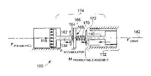
FIG. 7 and FIG. 8 show a non-limiting example of a compressor 100 configured
to
conserve the inertial force resident in the translatable assembly 140, thereby
advantageously having reduced rod acceleration peak load with respect to the
constant
velocity loading.
FIG. 7 shows a compressor having an accumulator 174. Accumulator 174 comprises
a
connecting rod 138 defining a first movable flange 162 and a second movable
flange 172.
The accumulator 174 further comprises a post 166 having an aperture 168, the
connecting
rod 138 being slidably received within the post 166. The accumulator 174
further
comprises a first resilient member 164 and a second resilient member 170. As
shown in
FIG. 7, the resilient member 164 is disposed between movable first flange 162
and fixed
post 166. Similarly, resilient member 170 is disposed between movable second
flange
172 and fixed post 166. The resilient members are configured such that, when
the
translatable assembly 140 is accelerating, the resilient members (164,170)
apply a force
directed in substantially the same direction as that of drive 132 on the
assembly 140,
thereby reducing the force the drive assembly would otherwise need to apply in
order to
accelerate the assembly 140. The resilient members apply such force by
returning to their
respective relaxed states, as illustrated in the exemplary embodiment
respectively as a
compressed spring 164 and extended spring 170.
In like manner, resilient members are configured such that, when the
translatable
assembly 140 is decelerating, the resilient members (164,170) apply a force
directed in
substantially opposite same direction as that of the motion of translatable
assembly 140,
thereby decelerating the speed of assembly 140 and reducing the force the
drive assembly
132 would otherwise need apply to the assembly 140 in order to decelerate the
assembly
140. The resilient members apply such force by being deformed from their
respective
11
CA 2873483 2018-03-09
CA 02873483 2014-11-13
WO 2013/171126
PCT/EP2013/059710
relaxed states (not shown). As such, the accumulator 174 has the technical
effect of
'banking' the inertia resident in the moving translatable assembly 140 during
a first
assembly movement by decelerating the assembly, and returning that inertia to
the
assembly 140 by accelerating the assembly in a second assembly movement.
During an interval when the drive 132 accelerates the translatable assembly
140 along
axis 142, the accumulator 174 advantageously applies force in concert with the
drive 132,
thereby assisting the drive 132 in both (a) overcoming the gas force applied
on the piston
first face 116, and (b) increasing the inertial force resident in the
translatable assembly
140. During such an acceleration interval, the force produced by drive 132
must satisfies
the equation:
F Drive ¨ (M Translatable Assembly) * a + F Piston Face F Accumulator
(Equation 2)
During an interval when the drive 132 decelerates the translatable assembly
along axis
142, the accumulator 174 advantageously applies force in concert with the
drive 132,
thereby assisting the drive 132 in removing inertial force resident in the
translatable
assembly 140, thereby decelerating the assembly 140 in the head-end direction.
During
such a deceleration interval, the force produced by drive 132 satisfies the
equation:
F Drive = (M Translatable Assembly) * a) + F Piston Face F Accumulator
(Equation 3)
As shown in Equation 2 and Equation 3, the accumulator 174 has the technical
effect of
reducing the force that the drive 132 needs produce in order to accelerate the
translatable
assembly 140. Expanding the "F Accumulator" term of Equation 2 and Equation 3
for an
accumulator comprising a single spring, the force produced by the drive
satisfies the
equation:
F Drive = (M Translatable Assembly) * F Piston Face (k * X) (Equation 4)
Where k is a spring constant, and X is the displacement of the spring end
connected to the
translatable member from its equilibrium position. The springs (164,170) shown
in FIG.
12
CA 02873483 2014-11-13
WO 2013/171126
PCT/EP2013/059710
7 and FIG. 8 are illustrative only, and other force banking devices are within
the scope of
the present invention.
For example, in an embodiment a capacitor (not shown) having a first conductor
(not
shown) fixed and a second conductor (not shown) attached to the translatable
assembly
are separated by a dielectric (e.g. air); in this way, the capacitor has
moving plates (to be
precise one plate moves with respect to the other plate) and thus has a
variable
capacitance. According to a variant of this embodiment, the dielectric-
occupied distance
between the two conductive plates varies with translation of the translatable
assembly.
The first and second conductors may be charged once-for-all and left isolated
during
operation of the compressor, or may be charged differently and left isolated
during
distinct operating periods of the compressors, or may be permanently connected
to a
constant voltage generator during operation of the compressor, or may be
permanently
connected to a variable voltage generator during operation of the compressor
(typically
the voltage of the generator is varied slowly with respect to the oscillation
period of the
translatable assembly). Such an accumulator stores a changeable electric
charge
corresponding to movement of the translatable assembly, the capacitor thereby
banking
the inertial energy of assembly and being configured to supply the charge to
power a
subsequent translation of the translatable assembly. The use of one or more
capacitor
may be combined with the use of one ore more springs that may have a constant
or a
variable spring constant.
Advantageously, in embodiments having resilient members comprising a spring,
the
spring may be configured such that the drive actuates the translatable
assembly so as to
excite the translatable assembly at a resonance frequency of the spring. The
spring, in
turn, may be designed to make coincident the resonance period with a desired
actuation
time. Alternatively, the spring may be designed to make coincident a harmonic
of the
resonance period with the desired actuation time.
It is worth noting that the springs of the embodiments of the present
invention may have a
spring constant that is constant with respect to time and space which
corresponds to the
13
252211
most common case for helical springs; alternatively, the spring constant may
vary in time
and/or in position, in particular along its length (i.e. it depends on the
degree of
compression of the spring).
FIG. 9 shows an embodiment of a variable accumulator configured to vary
compressor
capacity by increasing stroke and maintaining actuation time, thereby allowing
for
magnet position to be optimized. In an illustrative manner, the illustrated
accumulator
174 comprises a resilient member having a plurality of selectable parallel
springs
(101,102,103,104,105,106,107,108). The number of springs used in a stroke can
be
changed, thereby altering the spring constant k shown in Equation 4, thereby
varying the
stoke length and optimizing the magnet position.
More in general, it may be said that the accumulator of the embodiment of FIG.
9
comprises a spring assembly having a first end coupled to the translatable
assembly and
a second end fixed with respect to the translatable assembly. This spring
assembly
comprises a plurality of springs and the spring constant of this spring
assembly is
adjustable; in fact, the springs have different spring constant and are
arranged in parallel
so to be selectively effective. Alternatively, a spring assembly may comprise
a plurality
of springs having different lengths and arranged in parallel so to have
different effective
strokes (i.e. in a first displacement range of the translatable assembly a
first set of
springs are active on the translatable assembly, in a second displacement
range a second
set of springs are active, in a third displacement range a third set of
springs are active, ... ).
The expression "arranged in parallel" is to be interpreted from the functional
point of
view; in fact, the axes of the springs may be parallel to each other (even
coincident as
a limit case) or inclined to each other.
FIG. 10 and FIG. 11 show an advantageous technical effect of the compressor
100 over
compressor 10 with respect to the peak force required to achieve a given
velocity profile.
FIG. 10 shows compressor cylinder 114 divided into three sections (AA,BB,CC)
by four
cylinder sectioning lines (150,152,154,156). Sectioning lines 150 and 152
define
14
CA 2873483 2018-03-09
CA 02873483 2014-11-13
WO 2013/171126
PCT/EP2013/059710
chamber section AA, sectioning lines 152 and 154 define chamber section BB,
and
sectioning lines 154 and 156 define chamber section CC. As shown in FIG. 9 and
with
respect to Equation 2, when the piston 112 is at bottom dead center in
cylinder section
AA, drive 132 applies head-end oriented force sufficient to overcome both (a)
the gas
force applied on the piston first face 116, and (b) increase the inertial
force resident in the
translatable assembly 40, thereby accelerating the translatable assembly 140
in the head-
end direction. When the piston 112 enters section BB, the force requirement
drops, drive
132 supplying force sufficient only to overcome (a) the gas force applied on
the piston
first face 116. Inertia of the translatable assembly 140 is constant in
cylinder section BB.
When piston 112 enters section CC, drive 132 once again supplies an increased
amount
of force governed by Equation 3, sufficient to overcome both (a) the gas force
applied on
the piston first face 116, and (b) remove inertial force resident in the
translatable
assembly 140, thereby decelerating the translation of the assembly 140,
causing the
assembly to stop and leaving the piston in its top dead center position.
FIG. 11 graphically illustrates the velocity and force changes of the above
discussion.
FIG. 11 shows velocity and force graphed against time, time appearing on the x-
axis,
velocity appearing on the left y-axis, and force appearing on the right y-
axis. Four graph
sectioning lines (150,152,154,156) corresponding to cylinder sectioning lines
(150,152,154,156) divide the graph into three sections (AA,BB,CC), each
section having
a common drive force level and translatable assembly acceleration rate. In
similar
manner to FIG.10, sectioning lines 150 and 152 in FIG. 11 define a first
portion of the
graph "AA" illustrating force application and piston acceleration in chamber
section AA,
sectioning lines 152 and 154 define a second portion of the graph "BB"
illustrating force
application and piston acceleration in chamber section BB, and sectioning
lines 154 and
156 define a third portion of the graph "CC" illustrating drive force
application and
piston acceleration in chamber section CC. A solid line labeled "velocity"
shows a piston
velocity trace during movement from bottom dead center to top dead center
common to
each compressor 10 and compressor 100. The broken line having triangular
markers
labeled "Force 10" shows drive force application by drive 32 of compressor 10
during
CA 02873483 2014-11-13
WO 2013/171126
PCT/EP2013/059710
movement from bottom dead center to top dead center position, while a broken
line
having circular markers labeled "Force 100" shows drive force application by
drive 132 of
compressor 100 during movement of piston 112 from bottom dead center to top
dead
center position. Advantageously, the peak force requirement is lower for
compressor 100
than compressor 10 in both region AA and CC, as illustrated in the chart where
the
"Force 10" trace diverges from the "Force 100" trace, the gap being labeled as
"Reduced
Force." The advantageous force requirement shown in FIG. 11 is illustrative
and non-
limiting; the acceleration/deceleration and constant velocity segments of
piston travel
may vary in different embodiments of the invention disclosed herein.
A further advantageous effect of compressor 100 is that existing linear motor
technology
can be adapted to construct machinery having commercially usefid capacity.
For example, in a first non-limiting embodiment, compressor 100 comprises an
electromagnetic drive assembly 132 having a synchronous linear motor. In this
embodiment, the stator 134 comprises a plurality of conductive coils and the
core 136
comprises a permanent magnet. The plurality of conductive coils is arranged
coaxially
and parallel with respect to the axis 142. Operatively, a coil within the
plurality of coils
can be individually energized, thereby generating a magnetic motive force
pushes against
core 136, thereby reciprocatably driving translatable assembly 140 along the
axis 142.
Alternatively, in a second non-limiting embodiment, compressor 100 comprises
an
electromagnetic drive assembly 132 having an asynchronous linear induction
motor. In
this embodiment, the stator 134 comprises a plurality of conductive coils and
the core 136
comprising a reaction plate constructed of a conductive material, such as
copper or
aluminum. The plurality of conductive coils is arranged substantially
coaxially or
parallel with respect to the axis 142. The plurality of coils connects to a
three-phase AC
power supply (not shown) and is configured such that, upon being energized, an
electric
current is induced in the reaction plate. The induced current produces a
magnetic field
that interacts with the coils, thereby producing a motive force that pushes
the core 136,
thereby reciprocatably driving translatable assembly 140 along the axis 142.
16
CA 02873483 2014-11-13
WO 2013/171126
PCT/EP2013/059710
FIG. 12 through FIG. 17 show embodiments of compressors electromagnetically
driven
by a magnetic-geared drive.
FIG. 12 shows a magnetically-geared drive 232 in accordance with an embodiment
of the
invention. The magnetically-geared drive 232 is coupled to a connecting rod
238 and
configured to reciprocatably translate piston 212 disposed within the cylinder
(housing)
214 in response to signals originating from sensors (not shown) or a control
system (not
shown), or combinations thereof. The magnetically-geared drive 232 includes a
core 236
disposed between a first stator and a second stator, the stators being
collectively
identified in FIG. 11 as stator 234. The core 236 is coupled to the connecting
rod 238,
and the core 236, connecting rod 238, and piston 212 comprise a translatable
assembly
240.
FIG. 13 shows an exemplary drive 332 suitable for the compressors disclosed
herein. In
the illustrated drive embodiment, the drive 332 includes a moveable core 336
and a stator
334. In the embodiment shown, the core 336 is outwardly disposed with respect
to the
stator 334. The core 336 includes a portion of the compressor connecting rod
338, and
further comprises a plurality of permanent magnets 376 of alternating
orientation
(indicated by arrows) formed on a surface 378 of the connecting rod 338. The
stator 334
includes a base 380 and a plurality of windings 382 coupled to the base 380.
The number
of permanent magnets 376 provided on the connecting rod 338 and the number of
windings 382 provided on base 380 may vary depending upon the compressor
application. Advantageously, the torque density provided by the exemplary
configuration
allows for a significant reduction in compressor size, resulting in a cost and
mass savings,
thereby advantageously reducing peak force requirements by reducing the mass
of
translatable assembly 340 (not shown). As indicated above, an outer base/inner
comprising a portion of the connecting rod 338 is one possible configuration
for the
compressor 300 (not shown) with integrated magnetic gearing. This is a non-
limiting
configuration. In another exemplary embodiment, the drive 332 includes an
outer
permanent magnet base and windings arrayed on a portion of the connecting rod.
In such
17
CA 02873483 2014-11-13
WO 2013/171126
PCT/EP2013/059710
an embodiment, the plurality of permanent magnets 376 is provided on an inner
surface
of the base 380.
FIG. 14 shows a magnetically-geared drive 432 in accordance with another
exemplary
embodiment of the present invention. In the illustrated embodiment, the core
436
.. comprises a portion of the connecting rod 438 and a plurality of permanent
magnets 476
of alternating orientation (shown by arrows) formed on an inner surface 478 of
the
portion of the connecting rod 438. The stator 434 includes a base 480 and a
plurality of
windings 482 coupled to the base 480. A plurality of stationary magnetic pole-
pieces 484
is disposed within an air gap 486 formed between the plurality of core magnets
476 and
the stator windings 482. Depending upon the compressor 400 (not shown)
requirements,
the pole-pieces 484 may be mounted to the base 480 (e.g., by stamping from the
same
lamination sheet as the stator core material) or may be separately mounted. In
one
embodiment, an air gap may be present between the base 480 and the pole-pieces
484. In
another embodiment, a non-magnetic material may be inserted between the base
480 and
the pole-pieces 484. The stationary pole-pieces 484 facilitate torque
transmission
between the magnetic field excited by the permanent magnet core 436 and the
magnetic
field excited by the stationary windings 482. The number of permanent magnets
476,
stator windings 482 and the pole-pieces 484 may be varied depending upon the
compressor application.
FIG. 15 shows a magnetically-geared drive 532 in accordance with another
exemplary
embodiment of the present invention. In the illustrated embodiment, the core
536
comprises a portion of the connecting rod 538 and a plurality of permanent
magnets 576
of alternating orientation (shown by arrows) formed on an inner surface 578 of
the
connecting rod 538. The stator 534 includes a base 580 and a plurality of
stator windings
.. 582 coupled to the base 580. A plurality of stationary magnetic pole-pieces
584 is
disposed within the air gap 586 formed between the core magnets 576 and the
stator
windings 582. In the illustrated embodiment, the pole-pieces 584 are
integrated to the
stator base 580. As discussed in the previous embodiment, the stationary pole-
pieces 584
18
CA 02873483 2014-11-13
WO 2013/171126
PCT/EP2013/059710
facilitate torque transmission between the magnetic field excited by the
permanent
magnet core 536 and the magnetic field excited by the stationary windings 582.
FIG. 16 shows a magnetically-geared drive 632 in accordance with another
exemplary
embodiment of the present invention. In the illustrated embodiment, the drive
632
includes a moveable core 638 disposed between a first stator 636 and a second
stator 696.
The core 638 comprises a plurality of permanent magnets 676 integrated with a
portion of
the connecting rod 638. Each stator includes a base (680,688) and a plurality
of stator
windings (682,690) coupled to their respective base. In the illustrated
embodiment, a
first set of stationary magnetic pole-pieces 684 is disposed within an air gap
686 formed
.. between the core magnets 678 and the stator windings 682. A second set of
stationary
magnetic pole-pieces 692 is disposed with an air gap 694 formed between the
core
magnets 678 and the windings 690. Similar to the embodiment illustrated in
FIG. 15, the
first set of stationary magnetic pole-pieces 684 may be integrated to the
stator first fixed
base 680. The second set of stationary magnetic pole-pieces 692 may be
integrated to the
stator second fixed base 688.
FIG. 17 shows a magnetically-geared drive 732 in accordance with another
exemplary
embodiment of the present invention. In the illustrated embodiment, the drive
732
includes a moveable core 736 disposed between a first stator 734 and a second
stator 796.
The core 736 comprises a portion of the connecting rod 738, a first set of
permanent
magnets 776 provided on a surface 778 of the connecting rod, and a second set
of
permanent magnets 798 provided on the surface 778 of the connecting rod. The
first
stator 734 includes a first fixed base 780 and a plurality of stator windings
782 coupled to
the first fixed base 780. The second stator 796 includes a second fixed base
796 and a
plurality of stator windings 790 coupled to the second fixed base 788. Similar
to the
.. embodiment illustrated in FIG. 15 and FIG. 16, stationary magnetic pole-
pieces (not
shown in FIG. 17) may be disposed between the rotor magnets and the stator
windings or
integrated into the stator cores.
19
CA 02873483 2014-11-13
WO 2013/171126
PCT/EP2013/059710
In the various magnetically-geared drive embodiments depicted above, the cores
of the
compressors are implemented with permanent magnet cores. However, it is also
contemplated that the integrated magnetic gearing may also be accomplished
through the
use of cores having wound field, squirrel cage, or switched reluctance poles.
In other
words, the core's magnetic field may be implemented through DC powered
electromagnets, in lieu of permanent magnets. Furthermore, with regard to the
stationary
pole-pieces that serve as flux modulation devices, the shape of such pieces
may be
embodied by other insert shapes in addition to square inserts, such as oval or
trapezoidal
shapes for example. The configurations illustrated in the above embodiments
are shown
as including three-phase windings for purposes of example. It should also be
understood
that a different number of phases might be used as well.
Advantageously, the embodiments shown in FIG. 12 through FIG. 17 allow for
varying
the speed and/or the volume swept by compressor piston by changing the timing
and/or
number of windings energized during a movement of the translatable assembly.
This
avoids the requirement to physically reconfigure the volume of the compression
chamber
(i.e. by turning down). These machines control capacity by mechanically
displacing the
head end of the compression cylinder with a manually operated crank, a feature
which is
more difficult to adapt to a controller programmed with a set of instructions
recorded on a
non-transitory machine readable media. In certain embodiments of the present
invention, these instructions instruct the controller to (a) select a subset
of windings to
energize in a translation of the translatable assembly, (b) sequentially
energize the
windings so as to translate the translatable assembly at a target speed. In an
embodiment,
the translation speed is further selected such that compressor operates at a
frequency
substantially equal to the accumulator resilient member resonant frequency,
thereby
causing the resilient member to rapidly accumulate/discharge translatable
member inertial
energy. In another embodiment, the compressor operates at a harmonic of the
resonant
frequency of the resilient member, thereby accumulating a greater amount of
inertial
frequency, though lesser than would be case at the resonant frequency of the
resilient
member.
CA 02873483 2014-11-13
WO 2013/171126
PCT/EP2013/059710
FIG. 18 shows an embodiment of an electromagnetically driven compressor 800
having a
solenoid drive 832.
FIG. 18 shows an exemplary compressor 800 having a bi-directional (BDE design)
electromagnetic drive 832. The drive 832 includes two cores, a first core 802
having an
aperture 806 and a second core 804 having an aperture 808. The cores may be
made of
iron or any other metal sheets with good magnetic properties to decrease size
and weight
of the drive. In one embodiment, the cores are made of iron-cobalt alloys. The
exemplary
drive 832 includes the first core 802 and the second core 804 having an "E"
shape. In
some other embodiments, the cores may have any other suitable shape including,
but not
limiting to "U" shape. The drive 832 further includes a plate 801 defined by
the
translatable assembly 840, the translatable assembly 140 being slidably
received by the
aperture 806 and aperture 808. In some embodiments, the drive may include four
cores.
The first core 802 includes a set of two coils 810 disposed within the first
core 802. The
second core 804 includes another set of two coils 803 disposed within the
second core
804. In some embodiments, the cores may include more than two coils. The
compressor
800 further includes an accumulator 874 having a first resilient member 864
and a second
resilient member 870 configured as described above to provide forces to assist
the
movement of translatable assembly 840 along translation axis 842. The hi-
directional
drive 832 drivably engages the translatable assembly 840, thereby
reciprocatably driving
the piston 812 within the cylinder (housing) 814 as explained above.
As discussed in the preceding sections, the shape of the core ofthe drive
described herein
may be, for example, an "E" shape or a "U" shape. To generate a high
electromagnetic
force in the core in a very short span of time, the core of the solenoid as
well as the plate
arc typically manufactured out of metal sheets to avoid eddy current effects
as eddy
current growing in the core may reduce the magnetic flux produced by the
electromagnetic force. In order to facilitate reasonable ease of fabrication
of the core out
of metal sheets, a suitable design configuration should be used. The exemplary
"E"
shaped or "U" shaped cores described herein can be easily fabricated from
metal sheets
21
CA 02873483 2014-11-13
WO 2013/171126
PCT/EP2013/059710
such as an iron sheet. Furthermore the "E" shaped core also provides a large
area for the
poles developed in the core once the coils are energized. Since the plunger is
aligned
through the center of the "E" shaped core, the magnetic force generated is
distributed
uniformly on both sides of the plunger (due to the uniform location of the
coils with
respect to the center of the "E" core and the movement of the plunger due the
electromagnetic force may be balanced adequately.
Operationally, piston 812 assumes the bottom dead center position (shown in
FIG. 18)
when the current through the coils 803 in the second core 804 is turned on.
Once the
coils 803 are energized, the translatable assembly 104 is pulled towards the
second core
804 (shown by arrow 805) thereby compressing the second resilient member 864.
This is
illustrated in FIG. 18. Alternatively, the piston 812 assumes the top dead
center position
(not shown) when the current through the coils 803 is turned off, and the
current through
the coils 810 in the first core 802 is turned on. As a result, the
translatable assembly 840
is pushed towards the first core 802 guided by the first resilient member 864,
and piston
812 translates to the top dead center position. Advantageously, the bi-
directional design
of the drive may cover longer strokes compared to the unidirectional designs
and
provides a higher force during the initial stage of the stroke than
conventional linear
motors. This higher force is due to the fact that in both the end positions
(either bottom
dead center or top dead center) of the stroke, the preloaded compressed
resilient members
864 or 870 provides a high initial force, which force pushes the translatable
assembly 804
and the plate 802 towards the opposite core. Hence the spring force
advantageously gets
added to the weak magnetic forces, present at the beginning of the stroke due
to the large
air gap between plate 802 and iron cores 802 and 804 and enhances the initial
force.
In a solenoid drive embodiment (not shown), one or both the cores may be
independently
translatable along the translation axis. Such adjustability advantageously
allows for
adjustment piston travel distance between bottom dead center position and top
dead
center position, thereby adjusting the capacity of the compressor. In
another
22
252211
embodiment, frequency and translation speed may be adjusted by compensating
for the
accumulator configuration as described above.
While only certain features of the invention have been illustrated and
described herein,
many modifications and changes will occur to those skilled in the art. For
example, FIG.
19 shows an embodiment of the invention where a compressor 601 further
comprises a
second cylinder (housing) 603, a translatable assembly 611 having a second
piston 605,
and first accumulator 607 and second accumulator on either side of the drive
632. The
device operates as described above, and advantageously doubles compression
cylinder
space, incorporating the advantages described above. Similarly, FIG. 20 shows
an
embodiment of the invention where a compressor 801 further comprises a second
cylinder (housing) 803, a translatable assembly 811 having a second piston
805, and first
accumulator 807 and second accumulator on either side of the drive 832. The
device
operates as described above, and advantageously doubles compression cylinder
space,
incorporating the advantages described above. It is, therefore, to be
understood that the
appended claims are intended to cover all such modifications and changes as
fall within
the scope of the invention.
In an embodiment of the invention, a method of operating a reciprocating
compressor
comprises accelerating a translatable assembly in a first direction.
Acceleration
comprises, from a substantially motionless state, applying force to the
translatable
assembly such that it achieves some desired velocity. Once the target velocity
is reached,
force is applied to substantially overcome the force applied at the piston
face of the
translatable assembly by the gas occupying the compression chamber of the
reciprocating
compressor. Accelerating the translatable assembly imparts inertia to the
translatable
assembly, and increases the kinetic energy resident in the translatable
assembly.
The method further comprises decelerating the translatable assembly while it
travels in
the first direction. Decelerating the translatable assembly is accomplished by
shifting a
portion of the inertia resident in the translatable assembly into the
accumulator, such as
by deforming the above-discussed resilient member. Decelerating the
translatable
23
CA 2873483 2018-03-09
CA 02873483 2014-11-13
WO 2013/171126
PCT/EP2013/059710
assembly reduces the inertia resident in the translatable assembly, and
reduces the kinetic
energy associated with the assembly during its movement in the first
direction.
The method additionally comprises accelerating the translatable assembly in a
second
direction using energy stored in the accumulator. In one embodiment, a
resilient
member, deformed during the first movement of the translatable assembly,
relaxes and
returns to its original state, thereby applying force to the translatable
assembly and
accelerating the assembly during its second movement.
It will be understood by those skilled in the art that various changes may be
made and
equivalents may be substituted without departing from the scope of the
invention. In
addition, many modifications may be made to adapt a particular situation or
material to
the teachings of the invention without departing from its scope. Therefore, it
is intended
that the invention not be limited to the particular embodiment disclosed, but
that the
invention will include all embodiments falling within the scope of the
appended claims.
24