Note: Descriptions are shown in the official language in which they were submitted.
CA 02873493 2014-12-05
Docket 11749C
PUSHUP EXERCISER HAVING MULTIPLE HAND POSITIONING
SPECIFICATION
Field of the:Invention
100011 This invention relates generally to fitness and exercise apparatus
and particularly to
fitness and exercise apparatus used to perform pushup exercises.
Background of the Invention
[0002] Perhaps one of the most well-known and frequently employed types of
exercises is
that generally referred to a "pushups". While pushups may be performed in a
variety of routines,
the most basic pushup exercise is performed by the participant laying face
down upon a floor
surface with the upper feet and toes supporting the lower portion of the body
and with arms
extended outwardly and downwardly placing hands approximately beneath the
participant's
shoulders. Frequently, the participant supports the participant's hands upon
the floor surface
using extended fingers and thumb to actually touch the floor surface. In this
position, the
participant then stiffens and maintains a rigid straight line body position
while pushing the body
upwardly using the participant's arms until the arms are fully extended and
the participant's body
is supported upon the foot and toes together with the participants hands.
Thereafter, the
participants simply lowers and raises the body using the participant's arms.
In many instances,
the objective of a "perfect" pushup is attained by lightly touching the chest
to the floor between
the participant's hands during each downward movement.
1
CA 02873493 2014-12-05
[0003] Among the many variations of pushup exercises utilized, one is well-
known for
accommodating persons having limited upper body and arm strength in which the
lower body is
supported upon the participant's knees rather that foot and toes. When so
supported, the pushup
requires substantially less upper body and arm strength for exercise. At the
opposite extreme,
persons seeking to increase the effort required for the pushup exercise often
utilize a single
supporting hand and perform the so-called one handed pushup. By way of further
variation,
participants often utilize different hand positions such as wider or narrower
spacing to add
variety to the pushup exercises. Additionally, participants may choose to
rotate the hand
positions upon the floor for further variation of the exercise.
[0004] Recognizing the long term popularity and effectiveness of pushups as
a fitness and
conditioning exercise, practitioners in the art have endeavored to provide a
variety of apparatus
which is utilized in performing exercises. One such example is an apparatus
produced and
marketed under the product name "the strength builder" which utilizes an
elongated flat board
having a plurality of closed end holes formed therein. A pair of cooperating
handles is provided
each of which includes an inverted U-shaped handle grip supported upon a small
generally flat
platform base. The platform base further includes a downwardly extending
generally cylindrical
post at one end of the platform. The posts on the handles are sized and shaped
to be received
within the closed end apertures one elongated board. The board further
includes a plurality of
indicia lines together with numerals to identify hand locations and angular
positions upon the
board for each of the handles. In its intended use, the user places the posts
of each of the handles
into the selected closed end apertures on the board and rotates the handles to
the desired angular
position upon the board. Thereafter, the user grips the upper portion of the
inverted U-shape
handle grips and performs pushup exercises thereon.
2
CA 02873493 2014-12-05
[0005) Another variation of pushup exercise product provided by
practitioners in the art is
sold under the product name "perfect pushup mobile unit" sold by Perfect
Fitness. The perfect
pushup mobile unit apparatus includes a pair of generally disk shaped circular
platforms each
having an inverted U-shape handle pivotally secured to the edges thereof, The
handles are
pivomble between a vertical position intended for use and a flat position
intended for storage and
transport. In the anticipated use of the perfect pushup mobile unit product
the participant grips
each inverted U-shaped handle and positions the circular bases thereof upon
the floor and
thereafter assumes the typical pushup position. The user is able to pivot thc
hand grip units to set
a particular rotational position of the participant's hands during the pushup
exercise. Thereafter,
the pushup exercise is carried forward in the conventional fashion. By way of
further variety, a
plurality of similar products are sold which are generally described in the
art as "pushup stands"
which are characterized by pairs of hand units each including a band grip
portion. In the most
typical stand configuration, the hand grip portion includes an inverted U-
shaped member having
downwardly extending legs each of which is joined to a short transverse floor
piece in a right
angle attachment Variations of this pushup stand apparatus are provided by
fabricating
variously formed tubular material shapes all of which are employed in a
similar manner to
perform pushup exercises.
[0006) While the foregoing described prior art devices have to some extent
improved the
art and have in some instances enjoyed commercial success, there remains
nonetheless a
continuing need in the art for ever more improved pushup exerciser apparatus.
3
CA 02873493 2014-12-05
Summary of the Invention
[0007] Accordingly, it is a general object of the present invention to
provide an improved
exercise apparatus suitable for pushup exercise activities. It is a more
particular object of the
present invention to provide an improved apparatus for pushup exercise which
facilitates and
orderly and organized sequence of hand positions during pushup exercises. It
is a still more
particular object of the present invention to provide an improved apparatus
for pushup exercise
which maintains the handles of the pushup apparatus in a secure non-pivoting
reliable and
repeatable position,
[was] In accordance with the present invention, there is provided apparatus
for performing
pushup exercises, the apparatus comprising: a generally planar board defining
a generally planar
top surface; a plurality of post receptacles formed in the top surface; a pair
of handle units each
having attachment means for engaging selected ones of the post receptacles in
a fixed location
and angular orientation upon the top surface; and a plurality of color indicia
formed on the top
surface in association with selected ones of the post receptacles, the color
indicia defining groups
of color indicia each group being distinguishable from other groups by a
characteristic color
whereby the post receptacles and the color indicia groups cooperate to define
selected positions
of the handle units upon the board.
Brief Description of the Drawinas
[00091 The features of the present invention, which are believed to be
novel, are set forth
with particularity in the appended claims. The invention, together with
further objects and
advantages thereof, may best be understood by reference to the following
description taken in
4
CA 02873493 2014-12-05
conjunction with the accompanying drawings, in the several figures of which
like reference
numerals identify like elements and in which:
100101 Figure 1 sets forth a perspective view of a pushup exerciser
constructed in
accordance with the present invention;
[00111 Figure 2 sets forth a top plan view of the present invention pushup
exerciser;
[00121 Figure 3 sets forth an enlarged partial perspective view of a
portion of the present
invention pushup exerciser;
[00131 Figure 4 sets forth a top plan view of the board portion of the
present invention
pushup exerciser,
[0014] Figure 5 sets forth a section view of the board portion of the
present invention
pushup exerciser taken along section lines 5-5 in Figure 4;
100151 Figure 6 sets forth an enlarged partial section oldie board joint of
the present
invention pushup exerciser shown in Figures 4 and 5;
[00161 Figure 7 sets forth a perspective view of the board portion of the
present invention
pushup exerciser shown in Figure 4 having segments thereof separated;
[00171 Figure 8 sets forth a partial perspective view of the joint
structure of the board
portion of the present invention pushup exerciser shown in Figure 7;
CA 02873493 2014-12-05
[0018] Figure 9 sets forth a bottom perspective view of the board portion
of the present
invention exerciser shown in Figure 4;
[0019] Figure 10 sets forth a perspective view of an exemplary handle
constructed in
accordance with the present invention;
[0020] Figure 11 sets forth a side elevation view of the handle shown in
Figure 10;
[0021] Figure 12 sets forth a section view of the handle shown in Figure
11;
[0022] Figure 13 sets forth a side elevation view of an alternate
embodiment handle
utilized in the present invention pushup exerciser;
[0023] Figure 14 sets forth a portion of the exerciser board utilized in
combination with the
alternate embodiment handle shown in Figure 13;
[0024] Figure 15 sets forth a portion of the cooperating board alternately
used in
combination with the handle shown in Figure 13;
100251 Figure 16 sets forth a perspective view of a further alternate
embodiment of the
present invention pushup exerciser; and
[0026] Figure 17 sets forth a perspective assembly view of the board
portion of the
alternate embodiment of Figure 16.
6
CA 02873493 2014-12-05
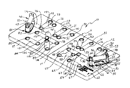
Description of the Preferred Embodiments = nven i = =
100271 Figure 1 sets forth a perspective view of a pushup exerciser
constructed in
accordance with the present invention and generally referenced by numeral 10.
Pushup exerciser
includes a board 11 formed by a pair of board sections 12 and 13 joined along
a board section
junction 14. In combination, board sections 12 and 13 form a generally planar
elongated board
11 which, in accordance with the present invention, receives a pair of handle
units 30 and 40 at
selected positions upon board 11 to fa.cilitate the multiple hand position
pushup exercise activity.
It will be apparent to those skilled in the art from the descriptions which
follow that the present
invention pushup exerciser facilitates a substantial variety of hand positions
and angles each of
which is maintained in a secure attachment of handle units 30 and 40 once a
position set has been
selected,
[00283 More specifically, pushup exerciser 10 is formed of a pair of
generally planar board
sections 12 and 13 joined along a board section junction 14 in the manner
described below in
Figures 5 and 6. Suffice it to note here that board section junction 14
provides a fixed
attachment which allows board sections 12 and 13 to perform as a single
extended generally
rigid board 11. Board section 12 defines a generally planar top surface 22
which in turn defines
a plurality of post receptacles 50 through 65 therein. Similarly, board
section 13 includes a
generally planar top surface 23 which in turn defines a plurality of post
receptacles 70 through
85. It will be noted that post receptacles 70 through 85 are arranged in a
pattern which forms a
mirror image of the pattern by which post receptacles 50 through 65 are formed
in surface 22 of
board section 12. Each of post receptacles 50 through 65 formed on board
section 12 and post
receptacles 70 through 85 formed on board section 13 comprise generally
cylindrical closed end
7
CA 02873493 2014-12-05
receptacles configured and sized to receive the cooperating cylindrical posts
formed on the
undersides of handle units 30 and 40 (seen below in Figures 10 and 11). Thus,
post receptacles
50 through 65 of board section 12 are arranged in a pattern which facilitates
multiple positioning
attachments of handle unit 30 upon top surface 22. Correspondingly, post
receptacles 70 through
85 of board section 13 are arranged in a mirror image pattern which
facilitates multiple positions
for attachment of handle unit 40 upon top surface 23 of board section 13.
[0029) In accordance with an important aspect of the present invention,
post receptacles
50 through 65 of board section 12 and 70 through 85 of board section 13 are
generally arranged
in pairs with each pair defining a selected handle unit position upon board
11. In further
accordance with an important aspect of the present invention, each pair of
post receptacles which
define a selectable handle unit position are joined by a color indicia. Each
color indicia extends
between the pair of post receptacles and which defines a color selected in
accordance with a
predetermined position code. Accordingly, top surface 22 includes a color
indicia 90 extending
between post receptacles 50 and 54. Similarly, a color indicia 91 extends
between post
receptacles 51 and 55 while color indicia 92 extends between post receptacles
52 and 56. A
color indicia 93 extends between post receptacles 53 and 56. A color indicia
94 extends between
post receptacles 56 and 57 while a color indicia 97 extends between post
receptacles 57 and 61
(partially obscured by handle unit 30). Continuing, a color indicia 95 extends
between post
receptacles 58 and 59 while a color indicia 96 extends between post
receptacles 59 and 60. A
color indicia 98 extends between post receptacles 58 and 63 while a color
indicia 99 extends
between post receptacles 62 and 63. A color indicia 100 extends between post
receptacles 59
and 62 while a color indicia 101 extends between post receptacles 64 and 65.
8
CA 02873493 2014-12-05
[00301 In a corresponding fashion, a color indicia 110 extends between post
receptacles 70
and 74 of board section 13 while a color indicia 1.11 extends between post
receptacles 71 and 75.
Similarly, a color indicia 112 extends between post receptacles 72 and 76
while a color indicia
113 extends between post receptacles 73 and 76 and a color indicia 114 extends
between post
receptacles 76 and 77 (obscured by handle 40). A color indicia 117 extends
between post
receptacles 77 and 81 (partially obscured by handle unit 40). A color indicia
115 extends
between post receptacles 78 and 79 while a color indicia 116 extends between
post receptacles
79 and 80. Finally, a color indicia 118 extends between post receptacles 78
and 83 while a color
indicia 119 extends between. post receptacles 82 and 83 and a color indicia
120 extends between
post receptacles 79 and 84 and a color indicia 121 extends between post
receptacles 84 and 85.
[0031] Board section 12 further includes a downwardly extending sidewall 24
while board
section 13 further includes a downwardly extending sidewall 25. Sidewalls 24
and 25 extend
about the entire periphery of board sections 12 and 13 respectively and are
joined along board
section junction 14 to form a rigid self-supporting member for board 11. In
the preferred
fabrication of the present invention, sidewalls 24 and 25 are sufficient to
provide depth for post
receptacles 50 through 65 and 70 through 85. The fabrication of sidewalls 24
and 25 and their
relationship to post receptacles 50 through 65 and 70 through 85 is set forth
below in Figure 9 in
greater detail. However, suffice it to note here that sidewalls 24 and 25
support top surfaces 22
and 23 respectively above the surface upon which board 11 is rested to
maintain clearance
between post receptacles 50 through 65 and 70 through 85 above the supporting
floor or surface
upon which board 11 is rested. In the preferred fabrication of the present
invention, board
sections 12 and 13 are fabricated as integrally formed molded plastic units
which, when joined
along board section junction 14 in the manner shown in Figures 5 and 6 and
described below,
9
CA 02873493 2014-12-05
form board 11 into an elongated rigid single exercise board. The fabrication
of board 11 in
separatable board sections 12 and 13 set forth below in Figures 5 through 8
facilitate convenient
separations of board sections 12 and 13 for easy storage and transport.
[0032) Figure 2 sets forth a top plan view of pushup exerciser 10 showing
board sections
12 and 13 joined along board section junction 14 to form a rigid board 11.
Figure 2 also shows
handle units 30 and 40 positioned upon board sections 12 and 13 respectively.
Thus, Figure 2
shows a top plan view of board 11 and handle units 30 and 40 in an exemplary
configuration for
the execution of the pushup exercise.
100331 More specifically, pushup exerciser 10 is formed of a pair of
generally planar board
sections 12 and 13 joined along a board section junction 14 in the manner
described below in
Figures 5 and 6. Suffice it to note here that board section junction 14
provides a fixed
attachment which allows board sections 12 and 13 to perform as a single
extended generally
rigid board 11. Board section 12 defines a generally planar top surface 22
which in turn defines
a plurality of post receptacles 50 through 65 therein. Similarly, board
section 13 includes a
generally planar top surface 23 which in turn defines a plurality of post
receptacles 70 th.rough
85. It will be noted that post receptacles 70 through 85 are arranged in a
pattern which forms a
mirror image of the pattern by which post receptacles 50 through 65 are formed
in surface 22 of
board section 12. Each of post receptacles 50 through 65 formed on board
section 12 and post
receptacles 70 through 83 formed on board section 13 comprise generally
cylindrical closed end
receptacles configured and sized to receive the cooperating cylindrical posts
formed on the
undersides of handle units 30 and 40 (seen below in Figures 10 and 11). Thus,
post receptacles
50 through 65 of board section 12 we arranged in a pattern which facilitates
multiple positioning
CA 02873493 2014-12-05
attachments of handle unit 30 upon top surface 22. Correspondingly, post
receptacles 70 through
85 of board section 13 arc arranged in a mirror image pattern which
facilitates multiple positions
for attachment of handle unit 40 upon top surface 23 of board section 13.
10034] in accordance with an important aspect of the present invention,
post receptacles 50
through 65 of board section 12 and 70 through 85 of board section 13 arc
generally arranged in
pairs with each pair defining a selected handle unit position upon board 11.
In further
accordance with an important aspect of the present invention, each pair of
post receptacles which
define a selectable handle unit position are joined by a color indicia. Each
color indicia extends
between the pair of post receptacles and defines a color selected in
accordance with a
predetermined position code. Accordingly, top surface 22 includes a color
indicia 90 extending
between post receptacles 50 and 54. Similarly, a color indicia 91 extends
between post
receptacles 51 and 55 while color indicia 92 extends between post receptacles
52 and 56. A
color indicia 93 extends between post receptacles 53 and 56. A color indicia
94 extends between
post receptacles 56 and 57 while a color indicia 97 extends between post
receptacles 57 and 61
(partially obscured by handle unit 30). Continuing, a color indicia 95 extends
between post
receptacles 58 and 59 while a color indicia 96 extends between post
receptacles 59 and 60. A
color indicia 98 extends between post receptacles 58 and 63 while a color
indicia 99 extends
between post receptacles 62 and 63. A color indicia 100 extends between post
receptacles 59
and 62 while a color indicia 101 extends between post receptacles 64 and 65.
100351 In a corresponding fashion, a color indicia 110 extends between post
receptacles 70
and 74 of board section 13 while a color indicia 111 extends between post
receptacles 71 and ?S.
Similarly, a color indicia 112 extends between post receptacles 72 and '76
while a color indicia
11
CA 02873493 2014-12-05
113 extends between post receptacles 73 and 76 and a color indicia 114 extends
between post
receptacles 76 and 77 (obscured by handle 40). A color indicia 117 extends
between post
receptacles 77 and 81 (partially obscured by handle unit 40). A color indicia
115 extends
between post receptacles 78 and 79 while a color indicia 116 extends between
post receptacles
79 and 80. Finally, a color indicia 118 extends between post receptacles 78
and 83 while a color
indicia 119 extends between post receptacles 82 and 83 and a color indicia 120
extends between
post receptacles 79 and 84 and a color indicia 121 extends between post
receptacles 84 and 85.
[00361 As mentioned above, post receptacles 50 through 65 and 70 through 85
are
organized and arranged in post receptacle pairs configured to receive handle
units 30 and 40
upon top surfaces 22 and 23 respectively at a variety of selectable positions.
Each of the handle
unit positions is selected to provide a particular set of benefits for the
pushup exercised being
performed. For example, the positions of handle unit 30 upon board section 12
identified by
color indicia 90, 91, 92 and 93 together with the mirror image positions of
handle unit 40 upon
board section 13 identified by color indicia 110, 111, 112 and 113 emphasized
shoulder muscle
development In accordance with an important aspect of the present invention,
color indicia 90,
91, 92 and 93 as well as color indicia 110, I 1 1 , 112 and 113 define a
common color (in this case
red). This common color provides easily understood and observed association of
the shoulder
muscle emphasizing handle unit positions_
[0037] In further accordance with the invention, it will be noted that
handle units 30 and 40
are fixed as to location and angular position by the pair of post on each
handle unit (seen in
Figures 10 and 11) and the post receptacle pair receiving them. Thus, the
location and angular
12
CA 02873493 2014-12-05
position of the handle units are securely established and maintained at the
selected handle unit
positions.
100381 In a similar manner, the handle unit positions of handle unit 30
upon board section
12 identified by color indicia 94,95 and 97 as well as the handle unit
positions of handle unit 40
upon board section 13 identified by color indicia 114, 115 and 117 emphasize
chest muscle
development. In accordance with the above-mentioned aspect of the present
invention, color
indicia 94, 95 and 97 as well as color indicia 114, 115 and 117 define a
common color (in this
case blue). Once again this common color provide easily understood and
observed association of
the chest muscle emphasis handle unit positions.
[00391 In further similarity, the handle positions of handle unit 30 upon
board section 12
identified by color indicia 96, 98 and 100 and the positions of handle unit 40
upon board section
13 identified by color indicia 116, 118 and 120 emphasis triceps muscle
development. Once
again, in accordance with the present invention, color indicia 96, 98 and 100
as well as color
indicia 116, 118 and 120 define a common color (in this case green). Once
again, this common
color provides easily observed and understood association of the triceps
muscle emphasis handle
unit positions.
100401 Finally, the positions of handle unit 30 upon board section 12
identified by color
indicia 99 and 101 and the positions of handle unit 40 upon board section 13
identified by color
indicia 119 and 121 emphasize back muscle development. In continued accordance
with the
present invention color indicia 99, 101, 119 and 121 define a common color (in
this case yellow).
Once again, this common color provides easily understood and observed
association of the back
muscle emphasis handle unit positions of the present invention ptishup
exerciser.
13
CA 02873493 2014-12-05
10041) Thus, in accordance with the present invention, handle units 30 and
40 are quickly
and easily positionable upon board sections 12 and 13 at a selected position
and are maintained
in a fixed secure location and angular position by the dual post, dual post
receptacle cooperation
between handle units 30 and 40 the receptacle pairs upon board sections 12 and
13. The color
association provided by the color indicia quickly identifies handle unit
locations which facilitate
or emphasize a chosen muscle group development without resort to any
additional materials or
directions. It will be apparent to those skilled in the art that while the
examples set forth herein
utilizes the color red for shoulder emphasis, blue for chest emphasis, green
for tricept emphasis
and yellow for back muscle emphasis, other colors may be utilized without
departing from the
spirit and scope of the present invention. The important aspect with respect
to this important
facet of the present invention is the provision of color coded muscle group
indicia having
common colors upon board 11 together with the secure location and angular
positioning
provided by the dual post configuration of the handle units and post
receptacle pairs.
100421 Figure 3 sets forth an enlarged partial perspective view of pushup
exerciser 10
showing handle units 30 and 40. As described above, pushup exerciser 10
includes a board 11
having a board section 13 within which a plurality of post receptacle pairs
are formed. As is also
described above, board section 13 defines a generally planar top surface 23
having a plurality of
color indicia formed between selected pairs of post receptacles. In Figure 3,
board section 13
shows post receptacles 76, 79, 80, 82, 83, 84 and 85. Board section 13 also
defines post
receptacles 77 and 81 which are obscured by handle unit 40. Color indicia 112,
113, 114, 116,
117, 119 and 121 are also formed upon surface 23 of board section 13.
14
CA 02873493 2014-12-05
[00431 Figure 3 also shows a perspective underside view of handle unit 30.
It will be
understood by those skilled in the art that handle unit 30 and 40 are
identical and that the
descriptions of handle unit 30 will apply equally well to handle unit 40.
Accordingly, handle
unit 30 includes an elongated base 31 defining a rectangular aperture 32 and
supporting a pair of
generally cylindrical downwardly extending posts 35 and 36. Handle unit 30
further includes a
pair of upwardly extending supports 33 and 34 positioned at opposed ends of
base 31. A
generally cylindrical grip bar 37 extends between grip supports 33 and 34 and
is secured in the
manner set forth below in Figure 12. Grip bar 37 further supports a handle
grip 38 preferably
formed of a resilient soft material such as foam rubber, foam plastic or the
like.
[00441 With handle unit 40 positioned as shown in Figure 3, it will be
noted that a portion
of color indicia 117 upon which handle unit 40 is attached is visible through
the aperture formed
in the base of the handle unit. This provides assistance in positioning handle
units 30 and 40 at
the desired location and within the desired color indicia group during
exercise activities.
[00451 Figure 4 sets forth a top plan view of board 11 which, as mentioned
above,
comprises board sections 12 and 13 joined along a board section junction 14.
As is also
mentioned above, board section 12 defines a top surface 22 having a plurality
of post receptacles
50 through 65 formed therein. As is also described above, board section 13
defines a top surface
23 having a plurality of post receptacles 70 through 85 formed therein. For
purposes of
illustration, Figure 4 omits the above-described color indicia which associate
the respective pairs
of post receptacles in the above-described manner. Of importance to note in
Figure 4 is the
increased difficulty which would arise in identifying the pairs of post
receptacles upon board II
without the aid of color indicia 90 through 101 and 110 through 121 shown
above in Figures 1
CA 02873493 2014-12-05
and 2. This emphasizes the great advantage to be provided by the present
invention color indicia
pairing of post receptacles which is provided in the manner set forth above.
In the preferred
fabrication of the present invention, board 11 is formed of board sections 12
and 13 to provide an
elongated board which may be readily separated to facilitate stacking board
sections 12 and 13
one upon the other for a more compact storage and transport. In their
preferred fabrication,
board sections 12 and 13 are formed of molded plastic or other suitable
material which provides
the advantageous or low-cost mass-production.
[00461 Figure 5
sets forth a section view of board 11 taken along section lines 5-5 in Figure
4. As described above, board ills formed of board sections 12 and 13 defining
respective top
surfaces 22 and 23 as well as respective sidewalls 24 and 25. As is also
mentioned above, board
sections 12 and 13 arc joined along board section junction 14. Of importance
to note in Figure 5,
is the extension of sidewalls 24 and 25 downwardly from top surfaces 22 and 23
respectively.
Thus, in the preferred fabrication of board 11, sidewalls 24 and 25 are longer
than the downward
extensions of post receptacles formed in top surfaces 22 and 23. To further
strengthen board 11
and provide greater support for handle units 30 and 40 during pushup exercise,
board 11 defines
a plurality of intermediate supporting ribs 40 through 49 spaced beneath board
sections 12 and
13. It will be noted that intermediate supporting walls 40 through 49 extend
downwardly from
top surfaces 22 and 23 by a distance equal to the downward extensions of
sidewalls 24 and 25.
As a result, the total weight of the user is distributed between sidewalls 24
and 25 together with
intermediate supporting walls 40 through 49 to provide significant rigidity
and strength for board
11.
16
CA 02873493 2014-12-05
[0047] Figure 6 sets forth a partial section view of board 11 showing board
section junction
14 in enlarged detail, More specifically, board section 12 defines a sidewall
24 and a top surface
22 as described above. As is also described above, board section 13 defines a
sidewall 25 and a
top surface 23. Board section junction 14 includes a generally U-shaped
upwardly open channel
wall 26 formed at the lower end of sidewall 25 of board section 13. Board
section junction 14
further includes a wall flange 27 formed in sidewall 24 of board section 12.
Of importance to
note is the formation of an elongated notch 28 formed in wall flange 27. Notch
28 facilitates the
insertion of wall flange 27 into channel wall 26 while maintaining the support
surface contact of
sidewalls 24 and 25. The extension of wall flange 27 into channel wall 26
secures the position of
board sections 12 and 13 and forms board section junction 14. This secure
attachment resists
any separation of board sections 12 and 13 during exercise activities. When
the user desires to
separate board segments 12 and 13 the user simply forces board section 12
upwardly while
forcing board section 13 downwardly which withdraws wall flange 27 from
channel wall 26.
Once separated, board sections 12 and 13 may be stacked for compact storage
and/or transport.
[0048] Figure 7 sets forth a perspective assembly view of board sections 12
and 13 in
which the board sections are separated from each other. As described above,
board section 12
defines a top surface 22 within which a plurality of post receptacles 50
through 65 are formed.
As is also described above, board section 12 includes a downwardly extending
sidewall 24.
Sidewall 24 includes a portion defining a wall flange 27 having a notch 28
formed therein.
100491 Board section 13 also described above includes a top surface 23
having a plurality
of post receptacles 70 through 85 formed therein. Board section 13 further
includes a
downwardly extending sidewall 25 having a channel wall 26 formed along one
portion thereof
17
CA 02873493 2014-12-05
Channel wall 26 defines an upwardly open generally U-shaped channel which
receives wall
flange 27 of board section 12 in the manner shown in Figure 6.
100501 Figure 8 sets forth a partial perspective view of board section 13
having sidewall 25
and top surface 23. Of importance to note in Figure 8 is the structure of
upwardly open U-
shaped channel wall 26.
(00511 Figure 9 sets forth a bottom perspective view of board 11. As
described above,
board 11 is formed of board sections 12 and 13 having respective downwardly
extending
sidewalls 24 and 25. Board sections 12 and 13 are joined along board section
junction 14 by the
cooperation of wall flange 27 and channel wall 26 as shown in Figure 6. For
added strength,
board section 13 includes a plurality of downwardly extending intermediate
support walls 40
through 44 while board section 12 includes a corresponding set of downwardly
extending
intermediate support walls 45 through 49. Support walls 40 through 49 and
sidewalls 24 and 25
cooperate to support the weight upon board 11. As described above, board
section 12 includes
post receptacles 50 through 65 while board section 13 includes post
receptacles 70 through 85.
[00521 Figure 10 sets forth a perspective view of handle unit 30. Handle
unit 30 includes
an elongated base 31 defining a generally rectangular aperture 32 therein.
Base 31 further
supports a pair of downwardly extending generally extending generally
cylindrical posts 35 and
36. Handle 30 further includes a pair of upwardly extending grip supports 33
and 34 together
with a generally cylindrical grip bar 37. Grip bar 37 extends between grip
supports 33 and 34
and is secured in manner set forth below in Figure 12. Suffice it to note here
that generally
cylindrical gip bar 37 is secured between grip supports 33 and 34 in a fixed
attachment. Handle
unit 30 further includes a generally cylindrical handle grip 38 formed upon
grip bar 37 and
18
CA 02873493 2014-12-05
preferably fabricated of a soft resilient elastic material such as foam rubber
or foam plastic.
Additionally, handle grip 38 may be fabricated of other nonslip materials such
as leather or the
like, While handle unit 30 may be fabricated in any suitable manner, in the
anticipated
fabrication of handle unit 30, a pair of molded plastic half portions will be
joined along a center
line 39 extending through grip supports 33 and 34, base 31 and posts 35 and
36. As is better
seen in Figure 12, these molded plastic half portions will be joined using
attachment such as a
conventional adhesive together with one or more fasteners as indicated by
fasteners 66 through
69 (seen in Figure 12).
[0053] Figure 11 sets forth a side elevation view of handle unit 30 which,
as described
above, includes a base 31 supporting a pair of generally cylindrical posts 35
and 36. Handle unit
30 further includes a pair of upwardly extending grip supports 33 and 34
together with a
generally cylindrical grip bar 37. Grip bar 37 extends between and is secured
by grip supports
33 and 34. Finally, handle unit 30 includes a resilient handle grip 38
supported upon grip bar 37.
[00541 Figure 12 sets forth a section view of handle unit 30 taken along
parting line 39
shown in Figure 10, As described above, handle unit 30 includes a pair of
mirror image molded
plastic half portions which are joined by a plurality of fasteners 66 through
69. Thus, handle unit
30 includes a base 31 defining an aperture 32 therein. Base 31 further
supports downwardly
extending generally cylindrical posts 35 and 36. Base 31 further supports a
pair of upwardly
extending grip supports 33 and 34. Grip supports 33 and 34 define respective
cylindrical bores
41 and 42. Grip supports 33 and 34 further define radially extending grooves
45 and 46 at the
interior ends of bores 41 and 42. Handle unit 30 further includes a generally
cylindrical grip bar
37 extending through bores 41 and 42. Handle grip 37 further defines a pair of
radially
19
CA 02873493 2014-12-05
extending flanges 47 and 48 which are received within grooves 45 and 46
respectively. Handle
unit 30 further includes a resilient handle grip 38 which, as mentioned above,
is preferably
formed of a resilient material such as foam rubber or foam plastic or other
suitable easily gripped
material.
100551 As mentioned above, handle units 30 and 40 are identical in
fabrication.
Accordingly, the descriptions and figures set forth above which illustrate and
describe the
structure of handle unit 30 will be understood to apply equally well and be
equally descriptive of
handle unit 40.
[00561 Figures 13 through 15 set forth an alternate embodiment of the
present invention in
which handle units 30 and 40 are replaced or supplemented by a handle unit
constructed to
utilize an alternative apparatus for securing, locating and angularly fixing
the position of the
handles upon the board portions of the present invention pushup exerciser. In
essence, the
embodiment set forth in Figures 13 through 15 replaces the pair of downwardly
extending posts
formed in handle units 30 and 40 (seen in Figures 10 through 12) with a single
fasted posts.
100571 More specifically, Figure 13 sets forth a side elevation view of a
handle unit
constructed in accordance with an alternate embodiment of the present
invention and generally
referenced by numeral 130. Handle unit 130 includes a generally rectangular
frame 131 having a
base portion 132 which in turn provides a bottom surface 133. Base 132
supports a downwardly
extending faceted post 134. Post 134 is faceted with to cooperate with a
faceted post receptacle
(receptacle 145 shown in Figure 14 receptacle 155 shown in Figure 15). The
fitceting of post
134 and cooperating faceted receptacles 145 and 155 provide the angular fixing
of the position of
h.suiclie 130 utilized in the present invention pushup exerciser. Handle unit
130 further includes a
CA 02873493 2014-12-05
resilient grip 135 formed upon the upper portion of frame 131. Grip 135 is
preferably formed of
a suitable resilient soft material such as foam rubber or foam plastic.
Alternatively, grip 135 may
be fabricated of a suitable leather or other material,
[00581 Figure 14 sets forth a partial top view of a board section 140 which
is fabricated in
general accordance with board sections 12 and 13 set forth above. Thus, board
section 140
includes a top surface 141 supporting pairs of generally cylindrical post
receptacles such as
receptacles 142 and 143. In further similarity to the above.described
embodiment, a color
indicia 144 extends between post receptacles 142 and 143. Board section 140
differs from board
sections 12 and 13 set forth and described above in that it further utilizes a
faceted post
receptacle 145. Post receptacle 145 is formed to receive faceted post 134 of
handle unit 130
(seen in Figure 13). In the example set forth in Figures 13 and 14, faceted
post 134 is hexagonal
in cross section. Correspondingly, faceted receptacle 145 is also hexagonal in
cross section.
However, it will be apparent to those skilled in the art that a different
faceted structure may be
utilized such as triangular or octagonal or square without departing from the
embodiment of the
invention shown in Figures 13 through 1$,
100591 In operations, handle unit 130 may be positioned upon board section
140 by
inserting faceted post 134 into faceted receptacle 145. It will be apparent
that the faceted
structure of pest 134 and receptacle 145 provide for a plurality of angularly
fixed positions for
handle unit 130 upon board section 140, Thus, the very desirable angular
fixing of handle unit
130 during the pushup exercise is maintained.
[00601 Figure 15 sets forth a portion of a board section constructed in
accordance with the
alternative embodiment of the present invention set forth in Figure 13 and 14
above. This further
21
CA 02873493 2014-12-05
alternate embodiment includes a board section 150 constructed in a similar
fashion to board
sections 12 and 13 set forth above. Thus, board section 150 includes a top
surface 151 within
which a pair of post receptacles 152 and 153 are formed. Board section 150
further includes a
faceted receptacle 155 surrounded by a color indicia 154. Color indicia 154
performs the same
function as the embodiment set forth above in Figures 3 through 3 in that
color indicia are
utilized to indicate the particular muscle groups to be emphasized.
[00611 Figure 16 sets forth a perspective view of a further alternate
embodiment of the
present invention pushup exerciser generally referenced by numeral 370. Pushup
exerciser 170 is
similar to exerciser 10 set forth and described above in that it includes a
board comprised of a
pair of board sections each defining a plurality of post receptacle pairs for
receiving and fixing a
pair of handle units on the board surface at selectable positions. Pushup
exerciser 170 differs in
that board section junction 210 is not straight-line as above , but rather
defines a pair of
oppositely directed "dove-tail" joints to join the board sections. In all
other respects, pushup
exerciser 170 is fabricated and operative in the manner described above.
[00621 Thus, pushup exerciser 170 includes board sections 171 and 172
joined at a board
section junction 210. Board section 171 defines a plurality of post
receptacles 191 through 206.
while board section 172 defines a plurality of post receptacles 175 through
190. Post receptacles
191 through 206 and 175 through 190 arc arranged in pairs to receive handle,
units 173 and 174.
Board sections 171 and 172 also support color indicia in the manner shown
above in Figure 1
which are omitted from the figure to avoid cluttering Figure 16.
[00631 Figure 17 sets forth an assembly view of board sections 171 and 172.
As mentioned
above, pushup exerciser 170 includes board sections 171 and 172 joined at a
board section
22
CA 02873493 2014-12-05
junction 210. Board section 171 defines a plurality of post receptacles 191
through 206. while
board section 172 defines a plurality of post receptacles 175 through 190.
Post receptacles 191
through 206 and 175 through 190 are arranged in pairs to receive handle units
173 and 174. As is
also mentioned above, board sections 171 and 172 also support color indicia in
the manner
shown above in Figure 1 which are omitted from the figure to avoid cluttering
Figure / 7.
100641 Board section 171 defines a junction wall 211 having a dove-tail
notch 212 and a
dove-tail extension 213 formed therein. Correspondingly, board section 172
defines a junction
wall 215 having a dove-tail notch 216 and a dove-tail extension 217 formed
therein. Board
sections 171 and 172 are joined by inserting dove-tail extensions 213 and 217
into dove-tail
notches 216 and 212 respectively. This provides a secure attachment between
board sections 171
and 172 during use which may be separated for storage and transport as needed.
po6si What has been shown is a novel pushup exerciser having multiple hand
positioning
handle units which are selectively attachable to a supporting board for
exercise of different
muscle groups during pushup exercise. The invention shown includes a
supporting board formed
of a pair of board sections joined along a board section junction to form a
rigid board structure.
The board sections may be separated to facilitate compact and convenient
storage and transport.
The pushup exerciser includes a plurality of post receptaclea disposed upon
the supporting board
in paired arrangement each paired arrangement defining a position, location
and angle
orientation of a handle unit received within. Coordinating color indicia are
provided in
association with each post receptacle pair to provide easy identification of
muscle group
emphasis for each receptacle pair and handle unit location.
23
CA 02873493 2014-12-05
[00661 While
particular embodiments of the invention have been shown and described, it
will be obvious to those skilled in the art that changes and modifications may
be made without
departing from the invention in its broader aspects. Therefore, the aim in the
appended claims is
to cover all such changes and modifications as fall within the true spirit and
scope of the
invention.
=
24