Note: Descriptions are shown in the official language in which they were submitted.
CA 02873675 2016-09-02
1
DEVICE FOR ATTACHMENT OF REPLACEABLE WEARING PART
A device for the attachment of a replaceable wearing part to be attached at a
leading
edge of an implement is described, wherein, at the leading edge, a supporting
surface
has been formed, which is arranged to receive and secure a wearing-part
holder, one of
the wearing-part holder and the wearing part forming an attachment projection
and the
other of the wearing-part holder and the wearing part forming a corresponding
socket,
and the attachment projection and the socket being provided with
corresponding, coop-
erating guide portions.
From an implement that is provided with a cutting edge, an edge, a tine, tooth
or the like
arranged to work against and move an unconsolidated mass, for example earth,
gravel,
shingle and so on, it is known to use replaceable wearing parts to increase
the durability
of the portion/portions that is/are subjected to heavy wear. The applicant's
own patent
publication EP 1259105 discloses such a wearing part for mounting on a leading
edge of
an implement, a holder being arranged on the implement and forming at least a
portion
of the leading edge, and the wearing part being provided with cooperating
guide ele-
ments forming a slidable fit of the socket-and-projection type for quick
replacement of
the wearing part without the use of fasteners or means other than a striking
tool.
The applicant's own NO 20093547 (corresponding to WO 2011/074983) discloses a
corre-
sponding system, but in which the wearing part is additionally formed with an
elevation
to direct the flow of earth away from an associated wearing-part holder.
The invention has for its object to remedy or reduce at least one of the
drawbacks of the
prior art or at least provide a useful alternative to the prior art.
The object is achieved through features which are specified in the description
below and
in the claims that follow.
In what follows, unless something else is expressly mentioned, the term
"length" is to be
understood as the extent of an element in the operative moving direction of a
wearing
part when the wearing part is arranged on the leading edge of an implement,
possibly the
extent of an axis lying in a plane coinciding with said moving direction.
Unless something
else is expressly mentioned, the term "width" is then to be understood as the
extent of
the element perpendicularly to said plane coinciding with the operative moving
direction
CA 02873675 2016-09-02
2
of the wearing part. Unless something else is explicitly mentioned, the term
"height" is
then understood as the extent of the element up from a plane coinciding with
the side
face of the wearing part on which the element is arranged.
For a leading edge of an implement which is provided with a cutting edge, an
edge, a
s tine, tooth or the like arranged to work against and move an
unconsolidated mass, for
example earth, gravel, shingle and so on, a replaceable wearing part is
arranged, an at-
tachment portion on the implement and said wearing part being provided with
cooperat-
ing guide portions which, in a horizontal projection, extend substantially in
the operative
moving direction of the implement. The wearing part and the attachment portion
are of
lo the socket-and-pin type as the wearing part may be driven into
frictional engagement
with the attachment portion by means of a force that acts substantially in the
longitudinal
direction of the guide portion, for example by the use of a striking tool, to
take a correct
working position without fasteners in the form of screws, bolts or the like
being used. The
attachment portion is arranged in association with a supporting surface, for
example by a
15 bracket that forms one of said socket and projection resting against the
sOpporting sur-
face, typically a ploughshare, a cultivator tine or a front portion of a
loader bucket (also
called a bucket jaw), and the wearing part exhibits at least one abutment
portion which,
when the wearing part is placed in its working position, rests against said
supporting sur-
face. Said abutment portion is brought to rest against the supporting surface
by the guide
20 portions of at least one of said socket and projection being slanted
relative to the sup-
porting surface, the guide portions exhibiting a decreasing distance to the
supporting sur-
face in the direction away from the leading edge of the implement. When the
wearing
part is being fitted, friction, in addition to the friction between the
corresponding guide
portions, will arise between the abutment portion(s) of the wearing part and
the support-
25 ing surface. This ensures a better attachment of the wearing part on the
implement than
what is achieved with the prior-art socket-and-pin type of attachment.
The invention relates more specifically to an assembly for attaching a
replaceable
wearing part to a leading edge of an implement, the assembly comprising: a
wearing-part
holder configured to be received on and fixed to a supporting surface formed
at the lead-
30 ing edge of the implement; and the replaceable wearing part including at
least one abut-
ment portion that rests supportingly against the supporting surface when the
replaceable
wearing part is attached to the wearing-part holder, wherein one of the
wearing-part
holder and the replaceable wearing part forms an attachment projection, and
the other of
CA 02873675 2016-09-02
3
the wearing-part holder and the replaceable wearing part forms a corresponding
socket,
wherein the attachment projection and the socket are each provided with
corresponding,
cooperating guide portions, the guide portions being formed as guide faces
facing the
supporting surface and being downwardly slanted relative to the supporting
surface from
a first end of each guide face proximal to the leading edge to a second end of
each guide
face distal to the leading edge.
The guide faces may be formed as upper side faces in recesses formed irithe
attachment
projection or the socket.
The wearing part may include one or more abutment portions which are provided
with
lo one or more elevations which, when the wearing part is fixed in the
wearing-part holder,
are resting supportingly against the supporting surface.
The elevations may at least partially be accommodated in a corresponding
recess ar-
ranged in the supporting surface.
The wearing part may include one or more serrated abutment portions.
The supporting surface may be arranged on a leading edge element taken from
the group
consisting of a tine, a share and a bucket jaw.
In what follows, an example of a preferred embodiment is described, which is
visualized
in the accompanying drawings, in which:
Figure 1 shows, in perspective, a wearing-part holder according to the
invention
arranged on a leading edge element of an implement;
Figure 2 shows, in perspective, a corresponding replaceable wearing
part according
to the invention;
Figure 3 shows, in a side view, a first embodiment of the arrangement
according to
the invention, in which the wearing part is positioned for connection to the
wearing-part holder;
Figure 4 shows, in a side view, a first embodiment of the arrangement
according to
the invention, in which the wearing part is connected to the wearing-part
holder;
=
CA 02873675 2016-09-02
4
Figure 5 shows, in a side view, a second embodiment of the arrangement
according
to the invention, in which the wearing part is positioned for connection to
the wearing-part holder;
Figure 6 shows, in a side view, a second embodiment of the arrangement
according
to the invention, in which the wearing part is connected to the wearing-part
holder;
Figures 7a, 7b and 7c show cross sections VI-VI according to Figure 3, where
Figure 7a
shows profiled abutment surfaces of the wearing-part holder as substantial-
ly V-shaped grooves, Figure 7b shows the profiled abutment surfaces of the
wearing-part holder as side faces in recesses extending inward and up-
wards from a lower outer boundary of an attachment projection, and Figure
7c shows the profiled abutment surfaces of the wearing-part holder as side
faces in a groove with a substantially rectangular cross section; and
Figure 8 shows, on a larger scale, a cross section of an embodiment of
the abutment
portion of the wearing part provided with elevations and a supporting sur-
face provided with corresponding recesses.
In what follows, reference being made to the drawings, preferred exemplary
embodi-
ments of a replaceable wearing part according to the invention will now be
described,
adapted for mounting on an implement with one or more working, leading edges
or fronts
which are arranged to work in a specific material and which are subjected to
wear over
time.
The preferred exemplary embodiments that are described are connected to
agricultural
implements for use in agricultural operations, but it will be understood that
the invention
has a wider application as it may be used on replaceable working shares of a
kind known
per se, and for other types and combinations of work tools that require
replaceable work-
ing shares to be fitted thereon, fixed by a wearing-part holder, whose
lifetime should de-
sirably be extended. =
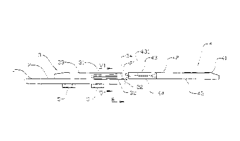
On an implement 1, a leading edge element 2 is arranged. The edge element 2
may be
formed as a replaceable share on a plough or as a levelling share, a jaw on a
loader
bucket, an end portion of a cultivator tine and so on. A surface portion of
the edge ele-
CA 02873675 2016-09-02
ment 2 forms a supporting surface 21 which extends in the working direction R
of the
implement, rearwards from a leading edge 22. On said supporting surface 21, a
wearing-
part holder 3 is fixed, shown here as attached to the edge element 2 by means
of at-
tachment bolts 5 passing through a portion of the wearing-part holder 3 and
the edge
5 element 2. The wearing-part holder 3 is provided with an attachment
projection 31 which
includes profiled abutment surfaces 32 which are arranged to engage
corresponding at-
tachment portions 431 of a socket 43 of a replaceable wearing part 4. The
abutment sur-
faces 32 include both portions arranged for lateral control of the wearing
part 4 and por-
tions arranged to guide the wearing part 4 into abutment against said
supporting surface
21 (vertical control), see the more detailed description below. The wearing-
part holder 3
is provided with a sliding surface 33 which is defined towards the wearing
part 4 by a
leading sliding-surface edge 34.
The replaceable wearing part 4 is provided with a front portion 41 which, in
the exempla-
ry embodiment shown, has the shape of a point arranged to easily penetrate
into a mass
in which the implement 1 is to be moved. The wearing part 4 is provided with a
sliding
surface 42 which, in the normal working direction R of the implement 1, is
arranged up-
stream of the wearing-part holder 3, the sliding surface 33 of the wearing-
part holder 3
and the sliding surface 42 of the wearing part 4 forming a substantially
uninterrupted
sliding surface.
zo The abutment surfaces 32 of the wearing-part holder 3 and the attachment
portions 431
of the wearing part 4 are, in what follows, also termed cooperating guide
portions.
In a first embodiment, the profiled abutment surfaces 32 of the wearing-part
holder 3 are
provided as substantially V-shaped grooves 32' (see in particular figure 7a).
Slanted side
faces 32a, 32b in grooves of this kind form both a lateral guide and a
vertical guide, that
is to say a guide in a direction perpendicular to the supporting surface 21.
In a second embodiment (see figure 7b), the abutment surfaces 32 are provided
as side
faces 32c, 32d in recesses 32" extending inwards and upwards from the lower,
outer
boundary of the attachment projection 31, the attachment projection 31
exhibiting a T-
profile. Vertical side faces 32c form the lateral guide and horizontal side
faces 32d form
the vertical guide.
In a third embodiment (see figure 7c), the abutment surfaces 32 are provided
as side
CA 02873675 2016-09-02
6
faces 32e, 32f in a groove 32¨ with a substantially rectangular cross section.
Vertical side
faces 32e form the lateral guide, and horizontal side faces 32f form the
vertical guide.
Other ways of providing said abutment surfaces 32 are possible as well, for
example by
combining the principles shown in figures 7a, 7b and 7c.
The present guide faces in the form of, respectively, the slanted faces 32a of
the V-profile
grooves 32', horizontal side faces 32d of the recesses 32, and the horizontal
side faces
=
32f of the rectangular-profile grooves 32¨ are slanted at an angle a (see
figure 3) to-
wards said supporting surface 21 in the direction away from the leading edge
22. In a
first exemplary embodiment (see figures 3 and 4), the corresponding attachment
portions
431 on the socket 43 of the wearing part 4 are slanted correspondingly so that
said slid-
ing surfaces 33, 42 lie in fairly coinciding planes when the wearing part 4 is
fixed to the
wearing-part holder 3. In a second exemplary embodiment (see in particular
figures 5
and 6), said attachment portions 431 on the socket 43 of the wearing part 4
are parallel
to the sliding surface 42 of the wearing part.
The wearing part 4 includes an abutment portion 44 which, as the wearing part
4 is being
connected to the wearing-part holder 3, is forced against the supporting
surface 21 of the
leading edge element 2 by the slant of the grooves 32' and horizontal side
faces 32d,
respectively. Thereby friction arises between the abutment portion 44 of the
wearing part
4 and the supporting surface 21 of the edge element 2 lying below, and this
helps to re-
duce the risk of the wearing part 4 unintentionally being loosened from the
implement 1,
=
for example in a situation in which the implement 1 is moved opposite to the
ordinary
working direction R.
The abutment portion 44 forms a rear portion of a bottom face 45 of the
wearing part 4,
that is to say opposite said sliding surface 42. The abutment portion 44 may
be formed
flush with the rest of said bottom face 45 as it is shown in figures 3 and 4,
or the abut-
ment portion may be formed as first elevations 46 projecting downwards from
the bottom
side of the wearing part 4 to compensate for the slant of the wearing part 4
relative to
=
the supporting surface 21, as it is shown in figures 5 and 6.
In figure 8, the abutment portion 44 is shown as provided with several
downward-
projecting second elevations 47 which extend transversely to the longitudinal
direction of
the wearing part 4 and, when the wearing part 4 has been fixed in the wearing-
part hold-
CA 02873675 2016-09-02
7
er 3, project into corresponding recesses 23 in the supporting surface 21. The
abutment
portion 44 may also be serrated or treated in some other way to provide
sufficient friction
between the abutment portion 44 and the supporting surface 21.
When the wearing part 4 is to be attached to the implement 1, it is moved with
the sock-
s et 43 towards the attachment projection 31 of the wearing-part holder 3
so that the
complementary abutment surfaces 32 and attachment portions 431 slidingly
engage with
each other. By means of a striking tool (not shown), the wearing part 4 is
driven onto the
wearing-part holder 3 as, through the slant of the guide portions 32 relative
to the sup-
porting surface 21, the abutment portion 44 of the wearing part 4 is moved
into abut-
io against the supporting surface 21.
When the wearing part 4 is being dismantled, it is driven away from the
wearing-part
holder 3 by hits against an appropriate portion of the wearing part 4.