Note: Descriptions are shown in the official language in which they were submitted.
CA 02873903 2014-11-18
WATER INLET VALVE
BACKGROUND OF THE INVENTION
1. Field of the Invention
The present invention relates to a water inlet valve, and more particularly to
a
water inlet valve which can stop water inflow in time under the condition that
water
tank accessories and a water tank fail.
2. Description of the Prior Art
A conventional water inlet valve comprises a water inlet pipe, a top cover, a
water stop pad, a back-pressure pad, a swing arm, and a buoy. The lower end of
the water inlet pipe is installed on a water supply pipe of a water tank. The
top
cover is installed on the upper end of the water inlet pipe. The interior of
the
water inlet pipe is formed with a water inlet cavity. The water inlet cavity
is
formed with a water stop surface having a water inlet. The water stop pad is
installed in the water inlet cavity, corresponding in position to the water
inlet and
located above the water stop surface. The top cover is formed with a
back-pressure hole. The middle section of the swing arm is pivotally connected
to the top cover. One end of the swing arm faces the back-pressure hole and is
installed with the back-pressure pad. The other end of the swing arm is
connected with an adjustment rod of the buoy. Seal members are provided
between the components to ensure water tightness. During use, when the water
level in the water tank descends, the buoy will descend by gravity to bring
the
swing arm to deflect. The back-pressure pad is to open the back-pressure hole.
The water from the water supply pipe flows through the water inlet pipe, the
water
inlet, the top cover, and the back-pressure hole to the water tank for water
inflow.
When the water level in the water tank ascends, the buoy will ascend by
buoyancy
to bring the swing arm to deflect. The back-pressure pad is to close the
1
CA 02873903 2014-11-18
back-pressure hole.
The water cannot enter the water tank from the
back-pressure hole of the top cover. The water stop pad is deformed by
back-pressure force to seal the water inlet of the water stop surface to stop
water
inflow.
However, the water tank accessories (a water inlet valve, a drain valve, a
button, and other sealing members) may fail after a period of time. For
example,
the drain valve cannot be closed tightly to leak slowly (a leak of less
water), the
part of the drain valve or the button fail and are unable to close to drain
all the time
(a leak of much water), or the water inlet valve is unable to stop water
inflow to
cause an overflowing. The aforesaid situations result in waste of water
resources.
Accordingly, the inventor of the present invention has devoted himself based
on
his many years of practical experiences to solve these problems.
SUMMARY OF THE INVENTION
The primary object of the present invention is to provide a water inlet valve.
Through the water inlet valve, water inflow can be stopped in time under the
condition that water tank accessories and a water tank fail, so that waste of
water
resources is reduced.
In order to achieve the aforesaid objective, the water inlet valve of the
present
invention comprises a water inlet pipe, a top cover, a water stop pad, a
back-pressure pad, a swing arm, and a buoy. A water inlet cavity is formed by
the
top cover and the interior of the water inlet pipe. A water sealing piston and
an
eccentric shaft are provided in the water inlet cavity and located below the
water
stop pad. One end of the eccentric shaft is inserted through the water sealing
piston. Another end of the eccentric shaft, in a closed state, extends out of
the
water inlet cavity. The water sealing piston is brought by the eccentric shaft
to
move up and down along an axial direction to close or open a water inlet of a
water stop surface. A water storage cylinder is fixed to the outside of the
water
2
. J
CA 02873903 2014-11-18
inlet pipe. The water storage cylinder has a water storage cavity at an upper
portion thereof and a lower water cavity at a lower portion thereof. The top
of the
water storage cavity is open. The lower water cavity has an upper air vent and
a
lower water inlet. A siphon is installed in the water storage cavity. One end
of
the siphon is disposed close to the bottom of the water storage cavity.
Another
end of the siphon is inserted through the bottom of the water storage cavity
and
communicated with the lower water cavity. A floater is provided in the water
storage cavity. A first magnetic element is installed on the top of the
floater.
The outside of the water storage cylinder is provided with a small buoy in a
liftable
way. The small buoy is provided with an opening and closing plate
corresponding
to the upper air vent of the lower water cavity. The opening and closing plate
is
capable of opening or closing the upper air vent as the small buoy is lifted
or
dropped. The circumferential edge of the top cover is formed with a gutter.
The
gutter is formed with a water drop opening facing the water storage cavity of
the
water storage cylinder. The outsides of the water inlet pipe and the top cover
are
provided with a connecting rod, a lever, and a bolt. One end of the connecting
rod is connected to one end of the lever. Another end of the connecting rod is
fixed to another end of the eccentric shaft. An energy storage spring is
provided
on the connecting rod or the lever. Another end of the lever is provided with
the
bolt which can be plugged or pulled out. The bolt is provided with a second
magnetic element corresponding to the first magnetic element for controlling
the
bolt to be pulled out and a restoring spring for the bolt to be restored and
plugged.
Preferably, a seal ring is provided between the eccentric shaft and an opening
of the water inlet cavity. A seal pad is provided above the water sealing
piston.
Preferably, a sponge is provided in the gutter for controlling the speed of
water
drops.
Preferably, the top of the water inlet pipe is formed with an inner
protrusion. A
3
CA 02873903 2014-11-18
water sealing spring is installed on the inner protrusion. The upper end of
the
water sealing spring is against the bottom of the water sealing piston. The
lower
end of the water sealing spring is against the inner protrusion.
Preferably, the side wall of the water storage cylinder is formed with a slide
trough. The upper air vent is disposed in the slide trough. The small buoy has
an upper counterweight cavity and a lower buoyancy cavity. The upper
counterweight cavity is slidably disposed in the slide trough. A lower portion
of an
outer side wall of the upper counterweight cavity is formed with a
communicating
hole. An upper portion of an inner side wall of the upper counterweight cavity
is
formed with the opening and closing plate corresponding to the upper air vent.
The opening and closing plate is inclined toward the upper air vent. The lower
end of the opening and closing plate is formed with an air release opening.
The
lower buoyancy cavity is located under the water storage cylinder.
Preferably, one end of the lever is formed with a fork. The fork has a long
outer side and a short inner side. The connecting rod is composed of a first
connecting rod and a second connecting rod. One end of the first connecting
rod
is disposed in the fork. Another end of the first connecting rod is pivotally
connected to one end of the second connecting rod. Another end of the second
connecting rod is fixed to another end of the eccentric shaft. The first
connecting
rod is formed with a lift rod extending from the first connecting rod. The
lift rod is
disposed in a lift trough formed at the outside of the top cover. An energy
storage
spring is provided in the lift trough to be against the lift rod.
Preferably, the inner side of the fork is formed with an inclined surface
which is
beneficial to move the first connecting rod.
Preferably, the connecting rod or the eccentric shaft is formed with a push
block to push the connecting rod and to restore the lever.
4
CA 02873903 2014-11-18
Preferably, another end of the lever or the bolt is formed with a slope to
guide
the bolt to be plugged in.
Preferably, the lever is provided with a protrusion beside a turning axle
thereof
to limit the turning angle of the lever.
The present invention is a structural improvement of a water inlet valve.
The improved water inlet valve of the present invention is installed in a
water
tank. Under an initial state, the bolt biased by the restoring spring is
inserted at
one end of the lever to position the lever as well as the connecting rod. The
connecting rod brings the eccentric shaft to rotate and position. The
eccentric
shaft brings the water sealing piston to descend so as to open the water
inlet. At
this time, the energy storage spring stores energy.
When in normal use, no malfunction, in the beginning of water inflow, the buoy
brings the swing arm to deflect downward. The back-pressure pad opens the
back-pressure hole. The water from the water supply pipe flows through the
water inlet pipe, the water inlet, the top cover, and the back-pressure hole
to the
water tank for water inflow. Partial water is guided by the gutter and flows
to the
water drop opening to form water drops to drop into the water storage cavity
of the
water storage cylinder. When the water level of the water tank ascends, the
water still enters the lower water cavity of the water storage cylinder. After
the
water level of the water tank ascends to a predetermined water stop level, the
buoy brings the swing arm to deflect upward. The back-pressure pad closes the
back-pressure hole again. The water stop pad generates a back-pressure force
to
block the water inlet of the water stop surface to stop water inflow.
When the drain valve is operated for a flush, the water level of the water
tank
and the water level of the lower water cavity of the water storage cylinder
will
5
CA 02873903 2014-11-18
descend. When the water level descends until the gravity of the small buoy is
greater than the buoyancy, the small buoy drops rapidly and brings the opening
and closing plate to move down to close the upper air vent of the lower water
cavity. The water level of the lower water cavity of the water storage
cylinder
descends continuously and slowly to form a negative pressure in the lower
water
cavity. When the negative pressure reaches a certain degree, the water in the
water storage cavity will be siphoned to the lower water cavity through the
siphon
until the water in the water storage cavity is siphoned out. The siphoning
will stop.
The water level of the water tank and the water level of the lower water
cavity of
the water storage cylinder keep on descending till flush. In the meantime, the
water level of the water tank descends until the gravity of the buoy is
greater than
the buoyancy. The buoy brings the swing arm to deflect downward once again.
The back-pressure pad is to open the back-pressure hole. The water stop pad
releases pressure to disengage from the water stop surface to open the water
inlet
for water inflow once again. At the same time, partial water is guided by the
gutter and flows to the water storage cavity as well as the lower water
cavity.
When the water level ascends to the predetermined position, the buoy will
bring
the swing arm to deflect upward. The back-pressure pad is to close the
back-pressure hole again. The water stop pad generates a back-pressure force
to block the water inlet to stop water inflow again.
When the part of the drain valve or the button is jammed and unable to close
to
cause a leak of much water, or the part of the water inlet valve malfunctions
and is
unable to stop water inflow to cause an overflowing, when in use, the water
inlet
valve will be in a feeding state all the time. Partial water is still guided
by the
gutter to flow into the water storage cavity of the water storage cylinder.
Because
the water inlet valve is in a feeding state all the time, the water level of
the water
storage cavity ascends continuously to bring the floater in the water storage
cavity
to ascend accordingly. When the first magnetic element of the floater is
aligned
6
CA 02873903 2014-11-18
with the second magnetic element of the bolt, the bolt is pulled out from the
lever
by magnetic action to release the positioning of the lever. The lever and the
connecting rod are biased by the energy storage spring to deflect. The
connecting rod brings the eccentric shaft to rotate. The eccentric shaft
brings the
water sealing piston to ascend to close the water inlet of the water stop
surface for
the water inlet valve to stop water inflow.
When the drain valve is leaking or the sealing portion of the water tank and
the
other part is leaking, namely, there is a leak of little water, the
counterweight water
level of the small buoy and the water level of the water tank are consistent
relatively. The small buoy is unable to bring counterweight and in a floating
state
all the time. The lower water cavity of the water storage cylinder
communicates
with the atmosphere all the time, so that its water level is consistent with
the water
tank and won't generate native pressure. The water in the water storage cavity
won't be siphoned. This way is done repeatedly. The water in the water storage
cavity is accumulated continuously, so that the water level of the water
storage
cavity ascends continuously to bring the floater in the water storage cavity
to
ascend accordingly. When the first magnetic element of the floater is
aligned
with the second magnetic element of the bolt, the bolt is pulled out from the
lever
by magnetic action to release the positioning of the lever. The lever and the
connecting rod are biased by the energy storage spring to deflect. The
connecting rod brings the eccentric shaft to rotate. The eccentric shaft
brings the
water sealing piston to ascend to close the water inlet of the water stop
surface,
such that the water inlet valve stops feeding.
The water inlet valve of the present invention is provided with the water
sealing
piston driven the eccentric shaft, the connecting rod, the lever, the plug,
the floater,
the water storage cylinder, and the small buoy to control turning of the
eccentric
shaft. Thus, the water inlet valve provides normal water feeding and water
stopping functions, and water inflow can be stopped in time under the
condition
7
CA 02873903 2014-11-18
that water tank accessories fail, so that waste of water resources is reduced.
BRIEF DESCRIPTION OF THE DRAWINGS
FIG. 1 is a perspective view according to a preferred embodiment of the
present invention;
FIG. 2 is an exploded view of the bolt according to the preferred embodiment
of
the present invention;
FIG. 3 is a schematic view showing the cooperative relationship of the bolt,
the
lever, and the connecting rod according to the preferred embodiment of the
present invention;
FIG. 4 is a schematic view showing the cooperative relationship of the bolt
and
the lever according to the preferred embodiment of the present invention;
FIG. 5 is a schematic view showing the structure of the connecting rod and the
gutter according to the preferred embodiment of the present invention;
FIG. 6 is a sectional view showing the structure of the water storage cylinder
and the small buoy according to the preferred embodiment of the present
invention;
FIG. 7 is a perspective exploded view showing the water storage cylinder and
the small buoy according to the preferred embodiment of the present invention;
FIG. 8 is a perspective view showing the position relationship of the water
storage cylinder and the small buoy according to the preferred embodiment of
the
present invention;
FIG. 9 is a schematic showing the structure of the water storage cylinder
8
CA 02873903 2014-11-18
according to the preferred embodiment of the present invention;
FIG. 10 is a sectional view showing the structure of the water storage
cylinder
and the small buoy of the preferred embodiment of the present invention in a
water
stop state;
FIG. 11 is a sectional view showing the structure of the water inlet cavity of
the
preferred embodiment of the present invention in a water stop state; and
FIG. 12 is a sectional view showing the structure of the water inlet cavity of
the
preferred embodiment of the present invention in a normal state.
DETAILED DESCRIPTION OF THE PREFERRED EMBODIMENTS
Embodiments of the present invention will now be described, by way of
example only, with reference to the accompanying drawings.
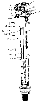
As shown in FIG. 1 and FIG. 12, the present invention disclosures a water
inlet
valve. The water inlet valve comprises a water inlet pipe 1, a top cover 2, a
water
stop pad 13, a back-pressure pad 21, a swing arm 3, and a buoy 31. This is the
essential structure of an existing water inlet valve. The lower end of the
water
inlet pipe 1 is installed on a water supply pipe of a water tank. The top
cover 2 is
installed on the upper end of the water inlet pipe 1. A water inlet cavity 10
is
formed by the top cover 2 and the interior of the water inlet pipe 1. The
water
inlet cavity 10 is formed with a water stop surface 14 having a water inlet
15. The
water stop pad 13 is installed in the water inlet cavity 10, corresponding in
position
to the water inlet 15 and located above the water stop surface 14. The top
cover
2 is formed with a back-pressure hole 22. The middle section of the swing arm
3
is pivotally connected to the top cover 2. One end of the swing arm 3 faces
the
back-pressure hole 22 and is installed with the back-pressure pad 21. The
other
end of the swing arm 3 is connected with an adjustment rod of the buoy 31.
Seal
9
CA 02873903 2014-11-18
members are provided between the components to ensure water tightness.
During use, when the water level in the water tank descends, the buoy 31 will
descend by gravity to bring the swing arm 3 to deflect. The back-pressure pad
21
is to open the back-pressure hole 22. The water from the water supply pipe
flows
through the water inlet pipe 1, the water inlet 15, the top cover 2, and the
back-pressure hole 22 to the water tank for water inflow. When the water level
in
the water tank ascends, the buoy 31 will ascend by buoyancy to bring the swing
arm 3 to deflect. The back-pressure pad 21 is to close the back-pressure hole
22.
The water cannot enter the water tank from the back-pressure hole 22 of the
top
cover 2. The water stop pad 13 is deformed by back-pressure force to seal the
water inlet 15 of the water stop surface 14 to stop water inflow.
The improvement of the present invention is described hereinafter.
As shown in FIG. 11 and FIG. 12, a water sealing piston 4 and an eccentric
shaft 41 are provided in the water inlet cavity 10 formed by the top cover 2
and the
interior of the water inlet pipe 1 and located below the water stop pad 13.
One
end of the eccentric shaft 411s inserted through the water sealing piston 4,
and
another end of the eccentric shaft 41, in a closed state, extends out of the
water
inlet cavity 10. The closed state means that between the eccentric shaft 41
and
the opening of the water inlet cavity 10 is in a closed state. For example, in
this
embodiment, a seal ring 42 is provided between the eccentric shaft 41 and the
opening of the water inlet cavity 10. The water sealing piston 4 is brought by
the
eccentric shaft 41 to move up and down along an axial direction to close or
open
the water inlet 15 of the water stop surface 14. Wherein, the water sealing
piston
4 can be directly brought by the eccentric shaft 41 to close the water inlet
15,
alternatively, the water sealing piston 4 can be indirectly brought by the
eccentric
shaft 41 to close the water inlet 15, namely, the rotation of the eccentric
shaft 41
enables the water sealing piston 4 to move up for a concession space. The
water
sealing piston 4 is pushed up by water pressure to seal the water inlet 15.
The
CA 02873903 2014-11-18
water sealing piston 4 can be brought by the eccentric shaft 41 to close the
water
inlet 15 in other similar ways which won't be enumerated one by one in this
specification. For a better water stop effect, this embodiment is further
provided
with a seal pad 43 above the water sealing piston 4, alternatively, the top of
the
water inlet pipe 1 is formed with an inner protrusion 11. A water sealing
spring 12
is installed on the inner protrusion 11. The upper end of the water sealing
spring
12 is against the bottom of the water sealing piston 4, and the lower end of
the
water sealing spring 12 is against the inner protrusion 11. When the eccentric
shaft 41 is rotated, as shown in FIG. 12, in a normal state, the long diameter
of the
eccentric shaft 41 cooperates with the water sealing piston 4 and the water
sealing
piston 4 descends to compress the water sealing spring 12 to open the water
inlet
of the water stop surface 14. In a water stop state, the short diameter of the
eccentric shaft 41 cooperates with the water sealing piston 4 and the water
sealing
piston 4 biased by the water sealing spring 12 ascends to close the water
inlet 15
15 of the water stop surface 14.
As shown in FIG. 6 to FIG. 10, a water storage cylinder 5 is fixed to the
outside
the water inlet pipe 1. The water storage cylinder 5 has a water storage
cavity 51
at an upper portion thereof. The top of the water storage cavity 51 is open.
The
water storage cylinder 5 has a lower water cavity 52 at a lower portion
thereof.
The lower water cavity 52 has an upper air vent 53 and a lower water inlet.
This
embodiment is directly formed with an opening. A siphon 54 is provided in the
water storage cavity 51. One end of the siphon 54 is disposed close to the
bottom of the water storage cavity 51, and another end of the siphon 54 is
inserted
through the bottom of the water storage cavity 51 and communicated with the
lower water cavity 52. A floater 55 is provided in the water storage cavity
51. A
first magnetic element 56 is provided on the top of the floater 55.
As shown in FIG. 2 to FIG. 9, the outside of the water storage cylinder 5 is
provided with a small buoy 6 which can be lifted. The small buoy 6 is provided
11
. .
CA 02873903 2014-11-18
with an opening and closing plate 61 corresponding to the upper air vent 53 of
the
lower water cavity 52, as shown in FIG. 6 to FIG. 9. The opening and closing
plate 61 is capable of opening the upper air vent 53 as the small buoy 6 is
lifted.
The opening and closing plate 61 is capable of closing the upper air vent 53
as the
small buoy 6 is dropped. In this embodiment, the side wall of the water
storage
cylinder 5 is formed with a slide trough 57. The upper air vent 53 is disposed
in
the slide trough 57. The small buoy 6 has an upper counterweight cavity 62 and
a lower buoyancy cavity 63. The upper counterweight cavity 62 is slidably
disposed in the slide trough 57, so that the small buoy 6 can be lifted or
dropped.
The lower portion of the outer side wall of the upper counterweight cavity 62
is
formed with a communicating hole 62. The upper portion of the inner side wall
of
the upper counterweight cavity 62 is formed with the opening and closing plate
61
corresponding to the upper air vent 53. For the opening and closing plate 61
to
close the upper air vent 53 better, the opening and closing plate 61 is
inclined
toward the upper air vent 53. For the opening and closing plate 61 to open the
upper air vent 53 better, the lower end of the opening and closing plate 61 is
formed with an air release opening 65. The lower buoyancy cavity 63 is located
under the water storage cylinder 5. The small buoy 6 can be in other
configurations capable of opening and closing the upper air vent 53 when the
water level ascends or descends. For example, the small buoy is located at the
middle lower portion of the water storage cylinder, without the upper
counterweight
cavity of this embodiment. This way also brings the opening and closing plate
to
open or close the upper air vent.
As shown in FIG. 5 and FIG. 9, the circumferential edge of the top cover 2 is
formed with a gutter 7. The gutter 7 is formed with a water drop opening 71
facing the water storage cavity 51 of the water storage cylinder 5.
Specifically,
the gutter 7 has apertures 72 to guide water. In order to control the speed of
the
water drop, a sponge is provided in the gutter 7.
12
CA 02873903 2016-02-29
,
,
As shown in FIG. 1 to FIG. 10, the outsides of the water inlet pipe 1 and the
top
cover 2 are provided with a connecting rod 8, a lever 9, and a bolt 91. One
end of
the connecting rod 8 is connected to one end of the lever 9, and another end
of the
connecting rod 8 is fixed to another end of the eccentric shaft 41. An energy
storage spring 85 is provided on the connecting rod 8. Another end of the
lever 9
is provided with the bolt 91 which can be plugged or pulled out. The bolt 91
is
provided with a second magnetic element 92 corresponding to the first magnetic
element 56. The first magnetic element 56 and the second magnetic element 92
are magnetic adsorption elements. Both the first magnetic element 56 and the
second magnetic element 92 can be magnets, alternatively, one is a magnet and
the other is an iron element which can be adsorbed by the magnet. The second
magnetic element 92 cooperates with the first magnetic element 56 to control
the
bolt 91 to be pulled out from the lever 9 to release the positioning of the
lever 9.
The bolt 91 is provided with a restoring spring 93. Through the restoring
spring
93, the bolt 91 can be restored to be plugged on the lever 9 for the lever 9
to be
positioned. For the transmission effect to get a balance and to be smooth, one
end of the lever 9 is formed with a fork 94. The fork 94 has a long outer side
941
and a short inner side 942. The connecting rod 8 is composed of a first
connecting rod 81 and a second connecting rod 82. One end of the first
connecting rod 81 is disposed in the fork 94, and another end of the first
connecting rod 81 is pivotally connected to one end of the second connecting
rod
82. The inner side 942 of the fork 94 is formed with an inclined
surface 943 which
is beneficial to move the first connecting rod 81. Another end of the second
connecting rod 82 is fixed to another end of the eccentric shaft 41. The first
connecting rod 81 is formed with a lift rod 83 extending from the first
connecting
rod 81. The lift rod 83 is disposed in a lift trough 84 formed at the outside
of the
top cover 2. An energy storage spring 85 is provided in the lift trough 84 to
be
against the lift rod 83. Wherein, the outer side 941 of the fork 94 is
designed to
be short for the first connecting rod 81 to push the lever 9, not subject to
the fork
13
CA 02873903 2016-02-29
94, so that the route of the first connecting rod 81 is enough. The inner side
942
of the fork 94 is designed to be long for the first connecting rod 81 to push
the
lever 9 to restore easily after the breakdown is released. The second
connecting
rod 82 or the eccentric shaft 41 is formed with a push block 86 to push the
connecting rod 8 and to restore the lever 9 conveniently. Another end of the
lever
9 (or the bolt 91) is formed with a slope 95 to guide the bolt 91. The lever 9
is
provided with a protrusion 96 beside the turning axle so as to limit the
turning
angle of the lever 9.
The present invention is installed in a water tank. Under an initial state, as
shown in FIG. 2 to FIG. 9, the bolt 91 biased by the restoring spring 93 is
inserted
at one end of the lever 9 to position the lever 9 as well as the connecting
rod 8.
The connecting rod 8 brings the eccentric shaft 41 to rotate and position. As
shown in FIG. 12, the eccentric shaft 41 brings the water sealing piston 4 to
descend so as to open the water inlet 15. At this time, the energy storage
spring
85 stores energy.
When in normal use, no malfunction, in the beginning of water inflow, the buoy
31 drops by gravity to bring the swing arm 3 to deflect. The back-pressure pad
21 opens the back-pressure hole 22. The water from the water supply pipe flows
through the water inlet pipe 1, the water inlet 15, the top cover 2, and the
back-pressure hole 22 to the water tank for water inflow. Partial water is
guided
by the gutter 7 and flows to the water drop opening 71 to form water drops to
drop
into the water storage cavity 51 of the water storage cylinder 5. When the
water
level of the water tank ascends, the water still enters the lower water cavity
52 of
the water storage cylinder 5. In this embodiment, the water enters the upper
counterweight cavity 62 of the small buoy 6 through the communicating hole 64.
After the water level of the water tank ascends, the buoy 31 ascends by
buoyancy
to bring the swing arm 3 to deflect. The back-pressure pad 21 closes the
back-pressure hole 22 again. The water cannot enter the water tank through the
14
CA 02873903 2016-02-29
back-pressure hole 22. The water stop pad 13 generates a back-pressure force
to block the water inlet 15 of the water stop surface 14 to stop water inflow.
When the drain valve is operated for a flush, the water level of the water
tank
and the water level of the lower water cavity 52 of the water storage cylinder
5 will
descend. In this embodiment, the water level of the upper counterweight cavity
62 of the small buoy 6 also descends slowly. When the water level descends
until the gravity of the small buoy 6 is greater than the buoyancy, the small
buoy 6
drops rapidly and brings the opening and closing plate 61 to move down to
close
the upper air vent 53 of the lower water cavity 52. The water level of the
lower
water cavity 52 descends continuously and slowly to form a negative pressure
in
the lower water cavity 52. When the negative pressure reaches a certain
degree,
the water in the water storage cavity 51 will be siphoned to the lower water
cavity
52 through the siphon 54 until the water in the water storage cavity 51 is
siphoned
out. The siphoning will stop. The water level of the water tank and the water
level of the lower water cavity 52 keep on descending till flush. In the
meantime,
the water level of the water tank descends until the gravity of the buoy 31 is
greater than the buoyancy. The buoy 31 brings the swing arm 3 to deflect once
again. The back-pressure pad 21 is to open the back-pressure hole 22. The
water stop pad 13 releases pressure to disengage from the water stop surface
14
to open the water inlet 15 for water inflow once again. At the same time,
partial
water is guided by the gutter 7 and flows to the water storage cavity 51 as
well as
the lower water cavity 52 and the upper counterweight cavity 62. When the
water
level ascends to the predetermined position, the buoy 31 will bring the swing
arm 3
to deflect. The back-pressure pad 21 is to close the back-pressure hole 22
again.
The water stop pad 13 generates a back-pressure force to block the water inlet
15
to stop water inflow.
When the part of the drain valve or the button is jammed and unable to close
to
cause a leak of much water, or the part of the water inlet valve malfunctions
and is
CA 02873903 2016-02-29
,
unable to stop water inflow to cause an overflowing, or the component of the
water
tank malfunctions to cause a leak, the water inlet valve will be in a feeding
state all
the time. Partial water is still guided by the gutter 7 to flow into the water
storage
cavity 51. Because the water inlet valve is in a feeding state all the time,
the
water level of the water storage cavity 51 ascends continuously to bring the
floater
55 in the water storage cavity 51 to ascend accordingly. When the first
magnetic
element 56 of the floater 55 is aligned with the second magnetic element 92 of
the
bolt 91, as shown in FIG. 10, the bolt 91 is pulled out from the lever 9 by
magnetic
action to release the positioning of the lever 9. The bolt 91 compresses the
restoring spring 93. The lever 9 and the connecting rod 8 are biased by the
energy storage spring 85 to deflect. In this embodiment, the energy storage
spring 85 pushes the lift rod 83 down to move the first connecting rod 81
down.
The first connecting rod 81 cooperates with the fork 94 to bring the lever 9
to
deflect. The first connecting rod 81 brings the second connecting rod 82 to
deflect. The connecting rod 8 (this embodiment is the second connecting rod
82)
brings the eccentric shaft 41 to rotate. As shown in FIG. 11, the eccentric
shaft 41
rotates to form a concession space for the water sealing piston 4 to ascend.
The
water sealing piston 4 is ascended by the action of water pressure to close
the
water inlet 15 for the water inlet valve to stop water inflow.
When the drain valve is leaking or the sealing portion of the water tank and
the
other part is leaking, namely, there is a leak of little water, the
counterweight water
level of the small buoy 6 and the water level of the water tank are consistent
relatively. The small buoy 6 is unable to bring counterweight and in a
floating
state all the time. The lower water cavity 52 of the water storage cylinder 5
communicates with the atmosphere all the time, so that its water level is
consistent
with the water tank and won't generate native pressure. The water in the water
storage cavity 51 won't be siphoned. This way is done repeatedly. The water in
the water storage cavity 51 is accumulated continuously, so that the water
level of
16
CA 02873903 2016-02-29
,
the water storage cavity 51 ascends continuously to bring the floater 55 in
the
water storage cavity 51 to ascend accordingly. When the first magnetic element
56 of the floater 55 is aligned with the second magnetic element 92 of the
bolt 91,
the bolt 91 is pulled out from the lever 9 by magnetic action to release the
positioning of the lever 9. The lever 9 and the connecting rod 8 are biased by
the
energy storage spring 85 to deflect. The connecting rod 8 brings the eccentric
shaft 41 to rotate. The eccentric shaft 41 brings the water sealing piston 4
to
ascend to close the water inlet 15, such that the water inlet valve stops
feeding.
After the malfunction of the water tank is solved to overcome the magnetic
force of the first magnetic element 56 and the second magnetic element 2, the
floater 55 is taken out from the bolt 91 and then the push block 86 is pushed
to
restore the first connecting rod 81, the second connecting rod 82, and the
lever 9.
The energy storage spring 85 stores energy once again. The eccentric shaft 41
is also restored to bring the water sealing piston 4 to move down to open the
water
inlet 15, such that the water inlet valve is restored to a normal state, as
shown in
FIG. 2 to FIG. 9.
Although particular embodiments of the present invention have been described
in detail for purposes of illustration, various modifications and enhancements
may
be made without departing from the scope of the present invention.
Accordingly,
the present invention is not to be limited except as by the appended claims.
17