Note: Descriptions are shown in the official language in which they were submitted.
CA 02874151 2014-12-11
DECORATIVE LIGHTING SYSTEM AND RELATED COMPONENTS
TECHNICAL FIELD
[00011
This patent application relates generally to
lighting systems and components. More specifically, this
patent application relates to decorative lighting systems
and components, for example, for use in or around a
building, such as a house, or surrounding structures.
BACKGROUND
[0002]
Lighting systems are commonly used for
decorative or environmental purposes.
For example,
during the .holidays, people often place electric lights
on their houses or landscaping surrounding their houses.
These lights typically consist of one or more lengths of
conductive wire, each length of wire having multiple
lights (e.g., light bulbs) distributed there along. The
= lengths of wire and/or lights can be secured to the
house, landscaping, or other object in various ways, such
as by wrapping the wire around the object, using clips
attached to the lights, or using fasteners such as nails
or tacks.
SUNNARY
100031
According to an embodiment, a lighting
system can comprise: a plurality of light modules
electrically coupled to a first cable, the first cable
having a first electric coupler, each light module
comprising:. a housing including one or more brackets
adapted to attach to an existing structure; and a light
emitting diode (LED) light source contained within the
housing, the LED light source electrically connected to
1
CA 02874151 2014-12-11
the first cable; and a controller adapted to couple to an
AC power receptacle to receive AC power, the controller
including an electrical output having a second electric
coupler adapted to physically and electrically connect to
the first electric coupler; wherein the controller is
adapted to illuminate the LED light sources of the
plurality of light modules according to a plurality of
pre-set programs, and the controller includes a user-
operable selector adapted to select one .of the pre-set
10. programs.
[0004j According to another embodiment, a component
for a lighting system can comprise: a cable including a
= first end with a first threaded electric coupler and a
second end with second threaded electric coupler; and a
plurality of light modules distributed along the cable,
each light module comprising: a housing including one or
more brackets adapted to attach to an existing structure;
a multi-color light emitting diode (LED) light source
contained within the housing; and a heat sink located in
= 20 the housing.
BRIEF DESCRIPTION OF THE DRAWINGS
100051 The foregoing aspects and other features and
advantages of the invention will be apparent from the
following drawings, wherein like reference numbers
= generally indicate identical, functionally similar,
and/or structurally similar=eleme.nts.
[0006] Figure 1 is a perspective view of an
embodiment of a lighting system mounted underneath the
eave of a house.
2
CA 02874151 2014-12-11
10007]
Figure 2 is a side view of an embodiment of
a light module of Figure 1, mounted underneath the eave
of a house.
= pow Figure 3 is an enlarged, side view of the
light module of Figure 2.
10009]
Figure 4 is a perspective view of an
embodiment of components of the lighting system of Figure
1.
1000101
Figure 5. is a side view of an embodiment .of
a lighting system mounted to a tree.
1000111
Figure 6 is a perspective view of an
embodiment of components of the lighting system of Figure
5 .
[00012]
Figures 7A, 7B, 7C, 7D, and 7E depict a
front-perspective, top, side, rear-perspective, and front
view, respectively, of an embodiment of a light module.
.
[00013]
Figures 8A, 8B, and 8C depict a front-
perspective, rear-perspective, and exploded view,
respectively, of another embodiment of a light module.
100014] Figures 9A, 9B,
and 9C depict a front-
perspective, rear-perspective, and exploded view,
respectively, of another embodiment of a light module.
[00015]
Figure 10 depicts another embodiment of a
= lighting system according to the present invention.
[0001.6] Figures 11A and 11B depict a front-
perspective and a side view, respectively, of the control
unit of Figure 10.
[00017]
Figures 12A, 12B, 12C, and 12D depict a
front-perspective, top, side, and exploded view,
respectively, of another embodiment of a light module.
[00018]
Figure 13 depicts another embodiment of a
lighting system according to the present invention.
3
CA 02874151 2014-12-11
[00019]
Figures 14A, 14B, 14C, and 14D depict a
front-perspective, top, side, and exploded view,
respectively, of another embodiment of a light module.
[00020]
Figure 15 depicts an electrical diagram of
an embodiment of a lighting system according to the
present invention.
DETAILED DESCRIPTION
(000211
Embodiments of the invention are discussed
in detail below.
In describing embodiments, specific
terminology is employed for the sake of clarity.
However, the invention is not intended to be limited to
the specific terminology so selected. A person skilled
in the relevant art will recognize that other equivalent
parts can be employed and other methods developed without
departing from the spirit and scope of the invention.
All references cited herein are incorporated by reference
as if each had been individually incorporated.
[00022]
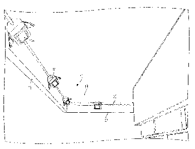
Referring to Figure 1, an embodiment of a
lighting system 10 is shown. Lighting system 10 Can be
used to provide decorative or environmental lighting in a
variety of interior or exterior applications.
For
example, the lighting system 10 can be mounted under the
eave 12 of a house, as shown in Figure I. Alternatively,
the lighting system 10 can be mounted to another part of
a house, such as along edges of the roof, or along the
= top of a fence. Other applications can include mounting
the lighting system to trees or other landscaping.
Interior applications are also possible, such as on or
around a ceiling or walls. Still further, the lighting
system 10 can be used without limitation on commercial
and industrial buildings, or on stadiums.
4
CA 02874151 2014-12-11
[00023] Figure
1 depicts an embodiment where a
plurality of light modules 14 are mounted under the eave
12, e.g., in a corner space formed between a fascia 16
= and a soffit 18, however, other mounting locations are
possible. As shown in Figure 1, each light module 14 can
include a housing having one or more mounting brackets
(described in more detail below), that allow the module
14 to be securely mounted under the eave, for example,
using nails, screws, adhesives, or other fasteners known
in the art. The
housing and mounting brackets can
facilitate mounting the light modules 14 under the eave,
or on some other structure, for extended periods of time.
[00024] Still
referring to Figure 1, electrical
cable 20 can extend between adjacent pairs of the light
modules 14. According to embodiments, the light modules
14 can be spaced equidistantly from one another along
cable 20, or alternatively, the light modules 14 can be
spaced in uneven intervals. According to other
embodiments, the location of each light module 14 on
cable 20 can be adjusted. As will be discussed below, a
plurality of cables can be linked in series (e.g., end-
to-end via waterproof connectors) or in parallel (e.g.,
connecting to a distributor via waterproof connectors) to
fit a desired installation and/or visual effect.
1000251 Figures 2 and 3
depict a side view of one of
the light modules 14 mounted under an eave 12. According
to embodiments, the light module 14 can be fastened to
the fascia 16 alone, the soffit 18 alone, or to both. In
the embodiment shown, the module 14 mounts at an angle a
(see Figure 3) with respect to the soffit 18 of about
45 . This may be done, for example, to maximize the cone
of light 22 emitted by the module 14 (see Figure 2),
5
=
CA 02874151 2014-12-11
however other angles are possible, such as an angle a
between about 30 and about 60 .
[000261
Figure 4 depicts an embodiment of lighting
system 10 detached from a building or other object. The
5 system 10 can include one or more of the cables 20 and a =
plurality of light modules 14, as described above. The
system can also include a power supply 24 that receives
electrical power, for example, from an AC plug 26 or
other connector adapted to plug into an electrical
10 outlet, such
as an 110V, 120V, 220V, or 240V AC outlet.
The system can also include a controller 28 connected
between the power supply 24 and the light modules 14.
According to an alternative embodiment, the power Supply
24 and the controller 28 can be integrated into a single
15 unit. Mating cord couplers 30 are provided to facilitate
disconnecting and reconnecting the cable 20 to the
controller 28, and/or to facilitate connection of
multiple cables 20 in an end-to-end arrangement, for
example, to extend the length of the light string.
20 According to embodiments, the cord couplers 30 can be
weather resistant, e.g., they can form a water tight seal
around the underlying electrical components. This can be
accomplished, for example, by using couplers 30 having
plastic or rubber material with mating threaded portions,
25 or by using threaded metal couplers having a rubber
gasket, O-ring, or the like. One of ordinary skill in
the art will appreciate from this disclosure that other
= structures can be used to from a weatherproof connection
between adjoined couplers 30, including those without
30 threads.
[000271
According to embodiments, the controller
houses a circuit, such as a printed circuit board (PCB),
that is programmed to provide a variety of user-
6
CA 02874151 2014-12-11
selectable light shows, such as seasonal and/or year-
round light shows.
For example, according to
embodiments, the user can press button 29 to scroll
through a menu and select the light pattern they desire.
5 Different
lighting patterns can range from steady burn
to light changing, color changing, blinking lights,
chasing lights, and other patterns and sequences as may
be desired by the user.
[000281
Figures 5 and 6 depict another embodiment of
= 10 a lighting system that can be mounted on a tree or other
freestanding object.
Lighting -system 10' is
substantially similar to the system described and shown
with respect to Figures 1-4, above, except for the
differences indicated below. As shown in Figures 5 and
= 15 6, lighting system 10' can include a distributor 32 that
allows multiple cables 20 to branch off from the
=
controller 28, for example, in parallel. Although
distributor 32 is shown as a stand-alone unit in Figures
and 6, alternative embodiments can have the distributor
20 32 integrated with the controller 28 and/or the power
supply 24.
The distributor 32 can also be connected to
the controller 28 and/or power supply 24 by removable
connection, such as by weatherproof couplers 30 described
above.
25 [000291 The
distributor 32 can also include a
plurality of cord couplers 30 to allow a user to connect
a desired amount of cables 20 to the distributor 32 to
fit their desired application. Additionally, multiple
distributors can be included to allow branching of the
30 cables 20 at a variety of locations. As shown in Figure
6, the embodiment of light modules 14 shown can include a
substantially flat mounting bracket with one or more
holes to facilitate surface mounting to a tree or other
7
CA 02874151 2014-12-11
structure, for example, using a nail, screw, or other
fastener. According to embodiments, the power supply 24
and/or the controller 28 can output AC power to the
modules 14. For example, the controller 28 and/or power
supply 24 can step down the voltage from 120V to 12V or
24V, although other variations are possible.
Alternatively, the controller 28 and/or power supply 24
can output DC power to the modules 14. According to DC
embodiments, the controller 28 and/or power supply 24 can
similarly step down the voltage output to the modules 14.
[000301
Figures 7A-E depict an embodiment of a light
module 14 from a variety of vantage points. As shown,
light module 14 can include a housing 34 that forms the
external structure of the light module 14. Housing 34
can contain a light source, such as one or more LEDs
(e.g., multicolor or RGB LEDs), halogen light bulbs,
fluorescent light bulbs, etc., as well as associated
electronics and/or electrical connections. According to
an embodiment, housing 34 can be substantially watertight
to protect the elements located inside of it. According
to embodiments, housing 34 can be formed of plastic,
metal, or combinations thereof.
1:00 311
Still referring to Figures 7A-E, housing 34
can include one or more windows 36 formed, for example,
= 25 of transparent or translucent material, to permit light
to pass from the light source inside the housing.
According to embodiments, the window 36 can be clear or
colored. The housing 34 can also include one or more
brackets 38 adapted to mount the housing 34 onto another
structure.
For example, in the embodiment shown,
brackets 38 include apertures 40 that permit screws,
= nails, or other fasteners to pass through the brackets 38
and secure the housing in place on a structure. One of
8
CA 02874151 2014-12-11
ordinary skill in the art will recognize from this
disclosure that other types of fastener arrangements can
be used instead of the apertures 40 and screws or nails.
The housing 34 also includes openings 42 at each end to
redeive the cable 20, preferably in a watertight fashion.
For example, a threaded compression gasket can secure
the cable 20 in each opening 42. Alternatively, silicone
glue, caulk, or other type of sealant can provide a
= waterproof seal between the cable and openings 42.
[00032] Referring to Figure 7A, according to an
embodiment, the housing 34 can comprise upper and lower
housing portions 34A, 34B joined together, for example,
using screws, and the brackets 38 can comprise a metal
component secured to the lower housing 38B, for example,
using screws. The upper and lower housing portions 34A,
= 34B can be formed of transparent or translucent plastic,
however, other configurations are possible.
[000331
Figures 8A-C depict another embodiment of a
light module 14 from a variety of vantage points,
including an exploded view. As shown, module 14 can
contain a light source, such as an LED 44. The LED 44
can be a multi-color LED, such as a RGB LED. The LED 44
can be electrically connected to cable 20 via a printed
circuit board (PCB) 46, however, other configurations are
possible. The window 36 can comprise part of a clamshell
member that surrounds the LED 44 and PCB 46, for example,
in a watertight fashion. Gaskets 48 can be located in
openings 42 to form a watertight seal around cable 20,
however, other types of seals can alternatively be used.
According to embodiments, the window 36 can be
transparent or translucent (e.g., colored), and the
surrounding portions can be opaque, however, in other
embodiments, the entire housing 34 can be transparent or
9
CA 02874151 2014-12-11
translucent.
In the embodiment of Figures 8A-C, the
brackets 38 are formed integrally with surrounding
portions of the housing, however, as discussed above in
other embodiments, the brackets can alternatively be
separate parts (e.g., metal) fastened to the remainder of
housing 34.
1000341
Figures 9A-C depict ancther embodiment where
the window 36 is part of the housing 34 itself. For
example, all or a portion of housing 34 could be made of
a transparent or translucent material, some of which
could optionally be covered with an opaque paint or other
coating to reduce the size of the window. Alternatively,
= the housing 34 could be co-molded or otherwise
constructed of two or more materials, at least one of
which is translucent or transparent. One of ordinary
skill in the art will appreciate from this disclosure
that a variety of different techniques can be utilized to
form one or more transparent or translucent windows in
the housing 34, either integrally or separately and
= 20 attached thereto. Figures 9A-C also depict a cover 50
that covers a rear portion of the housing 34. According
to embodiments, the window 36 can be colored, such as
translucent red, translucent blue, or translucent yellow,
etc. In the embodiment of Figures 9A-C, the brackets 38
are formed integrally with a top portion of the housing
34, however, according to alternative embodiments, the
brackets 38 can be selparate parts (e.g., metal) that are
fastened to the remainder of the housing 34.
[000351
Figures 10-14 depict additional embodiments
of the lighting system. The features of Figures ].0-14
,can be intermixed with the features of Figures 1-9, and
vice versa, except where they are technically
incompatible.
CA 02874151 2014-12-11
[000361 'Referring to Figure 10, according to
embodiments, the lighting system 100 can include a
plurality of light modules 114 electrically coupled to a
first cable 112, the first cable having a first electric
coupler 116. The lighting system 100 can also include a
controller 102 adapted to couple to an AC power
receptacle to receive AC power (e.g., 110V, 120V, 220V,
240V AC power), for example, through cable 104 and plug
106, however, other embodiments are possible.
The
controller 102 can include an electrical output 108
having a second electric coupler 110 adapted to
physically and electrically connect to the first electric
coupler 110. The first and second electric couplers 116,
110 can form a watertight seal, and can have a similar
arrangement as described previously for coupler 30.
= 1000371 The controller 102 can be adapted to
illuminate light sources of the plurality of light
modules 114 (e.g., LED light sources such as RGB LEDs)
according to a plurality of pre-set programs. Example
programs can include "starry night," "glimmer,"
"sparkle," "steady burn," and various light show themes, =
and combinations thereof.
Pre-set programs can also
= include different color themes, such as pure white, soft,
white, gold, red, yellow, green, blue, lavender, pink,
chasing colors (red-white-blue), and various combinations
thereof.
[000381
The controller 102 can include a user-
operable selector, such as buttons 120, 122 to select one
or more of the pre-set programs. For example, the user
= 30 can scroll through a list of the programs shown on
display 124, and select the desired program using buttons
120, 122. Alternatively, the selector can be operated
11.
CA 02874151 2014-12-11
remotely, for exami5le, through a Bluetooth connection,
infrared remote control, or other remote signal.
[000391
Although not shown in Figure 10, the
lighting system 100 can include additional sets of light
=
5 modules 114 located on additional cables 112. For
example, a second plurality of light modules can be
electrically coupled to a second cable. The first cable
112 can have a third electric coupler 118, e.g., located
opposite to coupler 116, and the second cable can include
a fourth electric coupler (not shown) adapted to
= physically and electrically connect to the third electric
coupler 118, e.g., in a similar manner discussed above
with coupler 30. In this manner, multiple sets of cables
112 and light modules 114 can be connected end-to-end to
achieve a desired length.
1000401
Figures 11A and 11B are perspective and side
views, respectively, of the controller 102. Referring to
Figures 10, ilAi and 118, the controller 102 can include
an integrated power supply (not shown) that is located in
the housing of controller 102. For example, the power
supply can receive the AC input from cable 104, and
convert the AC power for downstream use by the controller
102 and/or light modules 114. Alternatively, the power
supply can be separate from the controller 102, for
example, as shown in the embodiments of Figures 4 and 6.
[000411
According to embodiments, the controller 102
can output AC power to the light modules 114 through the
electrical output 108. For example, the controller 102
(or power supply) can step down the AC power to 12V or
24V for transmission to the light modules, however, other
values are possible. Alternatively, the controller 102
can output DC power to the light modules 114 through the
electrical output 108. According to DC embodiments, the
CA 02874151 2014-12-11
controller (or power supply) can step down the DC power
to 12V, 24V, or other voltage suitable for use by the
= light modules 114.
Figures 12A-D depict an embodiment of one of
the light modules 114.
Light modules 114 can be
substantially similar to the embodiments described in
Figures 1-9. Accordingly, only noteworthy differences
will be described below. As shown in Figures 12A and
128, light module 114 can include first and second
=10 mounting brackets 116, 118 that are inclined at different
angles. For example, first mounting bracket 116 can be
substantially co-extensive with the rear of the light
module housing, making the mounting bracket 116 suitable
for flush mounting the light module 114 to a surface.
Second bracket 118 can be inclined with respect to the
rear of the light module housing, for example, by an.
angle p of between about 15 and about 45 , for example,
about 30*. The second bracket 118 can be used as an
alternative to the first bracket 118 to mount the light
module 114 at an incline to a surface.
[000431
Referring to the exploded view of Figure
12D, the light module 114 can include a weather resistant
clamshell housing 120, 122 that can be completely
transparent or translucent, or can be opaque with a
transparent or translucent window 124, as has been
described in previous embodiments. The housing 120, 122
can include the brackets 116, 118. The housing 120, 122
can also house a circuit board 130 (such as a printed
circuit board) supporting one ormore LEDs (e.g., multi-
color RGB LEDs) in electrical connection with the cable
112. The housing 120, 122 can also contain a heat sink
132 in thermal communication with the circuit board 130,
such that the heat sink draws heat away from the circuit
13
CA 02874151 2014-12-11
board 130 and LEDs, to maintain an acceptable temperature
for the LEDs. According to embodiments, the heat sink
132 can be formed of metal, such as aluminum alloys,
= copper, composites, or combinations thereof. The heat
sink 132 can also include fins (not shown) or other
= features configured to further draw heat away from the
circuit board 130.
1000441 As discussed above, the controller 102 can
send electrical power and/or a signal to the light
modules 114 in a manner that causes the various LEDs in a
Light string or sets of connected light strings to
illuminate in desired patterns, colors, and combinations
thereof.
[000451 Figure 13 depicts an embodiment where
controller 102 is used with a plurality of light modules
140 that are substantially the same as light modules 14
of Figures 8A-C, except that light modules 140 further
include a heat sink 142 similar to heat sink 132
described above.
[000461 Figure 15 depicts an electrical diagram of
an embodiment of a lighting system according to the
present invention. Figure 15 depicts a plug 200 adapted
to connect to an AC power receptacle, for example, to
plug into a 120V AC receptacle. The plug transMits the
AC power to the controller 202, which converts the AC
= Power (e.g., steps it down to 12V or 24V, and/or converts
it to DC power) for use by the microcontroller (CU), LCD
display, and Bluetooth or other remote connection 206.
According to the embodiment shown, the controller 202
then outputs the power (e.g. AC power) to a plurality of
series-connected light modules 208, 210, 212, 214, for
example, located on one or more light strings. Each of
the light modules can in turn include a power module 216
14
CA 02874151 2014-12-11
that receives AC power from the controller 202, an LED
218, and a MCU 220 that receives the AC power and the
signals from the controller 202, and uses those signals
to illuminate the LEDs 218 in the desired color and for
the desired duration. One of ordinary skill in the art
= will appreciate from this disclosure that other circuit
configurations can be used to illuminate the LEDs in the
desired colors and patterns.
1000471
The embodiments illustrated and discussed in
this specification are intended only to teach those
skilled in the art the best way known to the inventors to
make and use the invention.
Nothing in - this
specification should be considered as limiting the scope
= of the present invention. All examples presented are
representative and non-limiting.
The above-described
embodiments of the invention may be modified or varied,
without departing from the invention, as appreciated by
those skilled in the art in light of the above teachings.
It is therefore to be understood that, within the scope
of the claims and their equivalents, the invention may be
= practiced otherwise than as specifically described.