Note: Descriptions are shown in the official language in which they were submitted.
CA 02874889 2014-12-11
1 ASSEMBLY FACILITATING A PROPER SWING MOTION
2
3 BACKGROUND OF THE INVENTION
4
Field of the Invention
6 This invention is directed to an assembly which may be mounted
7 on the user's body or disposed, at least in part, remote from the
8 user and includes a receiver and a transmitter. The receiver and
9 the transmitter are cooperatively structured for wireless
communication of an activating signal from the transmitter to the
11 receiver during a "reactive segment", of the swing motion. As a
12 result an indicating signal is delivered to the user, by the
= 13 receiver, to indicate to the user when a complementary adjustment
14 of the user's body, such as hip rotation, should occur during the
swing motion.
16
17 DESCRIPTION OF THE RELATED ART
= 18 Many physical activities including, but not limited to,
19 various sports activities involve what may be generically referred
to as a "swing motion". The performance of a correct or preferred
21 swing in any one of a plurality of different sports activities or
22 exercises will typically involve the coordinated movement of
23 various portions of an individual's body including the hands, arms,
24 hips and legs.
With specific but nonexclusive reference to the game of golf,
1
CA 02874889 2014-12-11
1 perhaps the hardest portion of the swing motion involves the proper
2 turning of the torso, specifically including a timely turning or
3 rotation of the hips of the player. It is emphasized that while
4 certain examples presented herein will relate to the game of golf,
other activities involving the performance of a preferred swing
6 also require proper and timely hip rotation in order to perform the
7 swing in a preferred manner. As such, hip rotation during a
8 predetermined part of the swing will result in maximum power and
9 increased accuracy. In addition to golf, other sports activities
typically requiring a proper swing motion include baseball, hockey,
11 lacrosse, rugby, etc. In these activities a user utilizes an
12 appropriate or recognized sports club, such as a baseball bat,
13 hockey stick, lacrosse stick, etc. Accordingly, it is well
14 recognized that the preferred performance of a swing, when
utilizing any of the above noted sports clubs, includes the
= 16 pivoting or moving of the hips of the player during a preferred
17 part of the swing motion. In addition to sports involving the use
18 of a specific club, the activity of throwing a ball, such as during
19 the playing of football, baseball, etc. also involves a proper
swing motion and an appropriate hip rotation at a precise or
= 21 preferred part of the of the swing or throwing motion.
/9
Many training devices and techniques have been proposed for
23 aiding a person in the execution of a preferred or proper swing
24 motion. Such devices or techniques, while assumed to be at least
minimally operative for their intended purpose, may suffer from one
2
CA 02874889 2014-12-11
1 or more recognized disadvantages. By way of example many
2 conventional procedures involve the teaching or description of one
3 or more incorrect techniques during the performance of a swing
4 motion. Such negative techniques are presented to an individual in
an attempt to emphasize the proper or correct technique when
6 performing a given swing motion. Further by way of example, the use
7 of many known devices involve a significant expense and/or require
8 a significant amount of time to accomplish the intended training
9 procedure. Also, many of the known training devices or procedures
are significantly complex and/or may require additional
11 participants to facilitate the monitoring and evaluation of the
12 practice swings during the training procedure. In addition, such
13 known approaches may involve the presenting of a model or patterned
= 14 swing which an individual attempts to duplicate. As a result,
individuals attempting to improve or perfect a swing motion become
16 confused and frustrated resulting in a failure to continue
17 utilizing many of the known devices and/or techniques as set forth
18 above.
=
19 Therefore, there is a need in this area for a system, method
and/or assembly which facilitates the training of an individual in
21
the performance of a proper swing motion. Moreover, such a proposed
22 training assembly, etc. should be specifically, but not necessarily
23 exclusively, directed to the performance of a proper rotation or
24 turning of the hips during a specific part or "reactive segment" of
the swing motion. As indicated above, a preferred and proposed
3
CA 02874889 2014-12-11
1 training procedure and assembly should be significantly versatile
2 and be capable of modifying modify the training procedure to
3 accommodate a specific swing motion associated with a different
4 sports or other activity. Further, such individual activities may
or may not include the use of a sports club as indicated.
6
Also, a preferred and proposed assembly training an individual
7 in the performance of a preferred or proper swing motion should be
8 capable of being used independently of other individuals. However,
9 the operational versatility of such a proposed training assembly
should, in certain preferred circumstances, be capable of use in
11
coordination with at least one individual such as, but not limited
12 to a "swing coach". Finally, a proposed training assembly of the
13 type set forth herein should be relatively inexpensive, long-
14 lasting, easy to "install" or utilize and be capable of
accomplishing the intended purpose of facilitating a player's swing
16 motion, regardless of whether the swing motion involving a sports
17 club or merely the act of throwing.
18
19 SUMMARY OF THE INVENTION
The present invention comprises a training assembly structured
21 to facilitate the timely performance of a proper swing motion when
= 22 practicing or playing a sports activity. As indicated herein, many
23 sports activities involve the performance of a "swing motion"
24 including, but not limited to the game of golf, baseball, hockey,
lacrosse, etc. In these types of activities a user utilizes an
= 4
CA 02874889 2014-12-11
1 appropriate sports club such as a golf club, baseball bat, hockey
2 stick, lacrosse stick, etc. When involved in such activities, it is
3 well recognized that the preferred performance of a swing utilizing
4 any and/or all of the above noted type of sports clubs also
includes the pivoting, rotating or proper moving of the hips, on a
6 timely basis and during a predetermined part of the swing.
7 Moreover, the user must instigate and accomplish such hip movement
8 during a "reactive segment" or preferred part of the swing motion.
9 As used herein, the term "reactive segment" is meant to define and
describe a portion of the swing motion during which hip rotation or
11 other preferred hip movement should be initiated by an individual.
12 It is also emphasized that activities which do not involve the use
13 of a sports club, such as throwing a ball, also requires proper hip
14 rotation. Accordingly, the throwing of a ball such as during the
playing of football, baseball, etc. also involves a "swing motion"
16 and an appropriate, timely hip movement in order to assure proper
17 power and accuracy.
18
Therefore, one or more preferred embodiments of the assembly
19 of the present invention facilitate the performance of the
preferred swing motion by clearly indicating to the user the
21 "reactive segment" of the swing, during which the hips should be
22 properly rotated. As such, the assembly of the present invention
23 includes a receiver operatively disposed in a first predetermined
24 vicinity on or relative to the user. A transmitter is also
= 25 operatively, disposed in a second predetermined vicinity on or
5
CA 02874889 2014-12-11
1 relative to the user and also relative to the receiver. The
2 receiver and the transmitter are cooperatively structured for
3 wireless communication of an activating signal generated by the
4 transmitter and delivered therefrom to the receiver. Upon receipt
of the activating signal, the receiver is structured to transmit an
6 indicating signal to the user. The indicating signal is intended to
7 inform or indicate to the user when hip rotation should be
8 instigated. More specifically the user should be informed to
9 instigate hip rotation during the "reactive segment" of the swing
motion. Again, referring to the non-exclusive example of golf,
11 rotation of the hip movement may begin at the top of the back swing
12 and when the golfer begins the downswing.
13
Further, the form or configuration of the indicating signal
14 may vary dependent, at least in part, on the first and second
vicinities. Also, as used herein the first vicinity and the second
16 vicinity may be descriptive of the positions of the receiver and
17 transmitter relative to the user and relative to one another and
18 more specifically include, the relative locations and/or distances
19 between the transmitter and the receiver. Moreover, one preferred
embodiment of the present invention includes the first
21
predetermined vicinity defined by the receiver being mounted on the
22 user preferably at a predetermined location such as adjacent one
23 the hip of the user. When the receiver is so mounted, the
24 indicating signal delivered by the receiver may be in the form of a
generated sound of sufficient loudness to be easily heard during
6
CA 02874889 2014-12-11
1 the performance of the swing motion. As indicated, the receiver
2 generates the indicating signal upon receipt of the activating
3 signal from the transmitter, where in the transmitter generates and
4 communicates the activating signal during the aforementioned
= 5
"reactive segment" of the swing motion. In contrast, the indicating
6 signal may also comprise a mechanical impulse, movement and/or
7 vibration applied directly to the user. Such a mechanical impulse
8 will also serve to inform the user that the "reactive segment" of
9 the swing motion has been reached and that rotation or other
intended movement of the. hips must be instigated.
11
The receiver may include a variety of different wireless
12 communication devices specifically including, but not limited to, a
13 wireless mobile communication device such as a cell phone, smart
14 phone, etc. As such the mobile communication device may be pre-
programmed to generate the aforementioned indicating signal in the
16
form of a generated sound and/or mechanical vibration. As indicated
17 either the sound heard by the player or the mechanical vibration
18 felt by the player will inform the player that the reactive segment
19 of the swing motion has been reached.
In further contrast, the receiver may include or be
21
operatively associated with an impulse generator disposed in direct
22 confronting and/or engaging relation to the user body. Moreover,
23 the impulse generator may be in the form of an electrical impulse
24 generator, disposed an electrically conductive relation to a
predetermined portion of the players body. As such an electric
7
CA 02874889 2014-12-11
1 charge or electric shock is delivered to the body of the user.
2 Naturally, the "strength" of such an electric shock will not be
3 such as to injure or cause pain or discomfort, but rather be
4 sufficient to be clearly noticed by the player and be indicative
that the reactive segment of the swing motion has been reached. In
6 the alternative the impulse generator may be structured to deliver
7 a mechanical impulse, such as in the form of a mechanical
8 vibration, as indicated above.
Also, the mechanical impulse
9 generator may be in the form of a spring-loaded plunger device
which, upon receiving the activating signal, generates the
11 indicating signal by triggering the plunger to mechanically impulse
12 the predetermined body portion of the user.
13
In cooperation with. the receiver being mounted in a first
14 predetermined vicinity, such as on the user's body, the second
predetermined vicinity may be defined by the transmitter also being
16 mounted on the user's body. In one preferred, but non-exclusive
17 example, when the user is right-handed, the receiver may be mounted
18 adjacent the right hip and the transmitter may be mounted on the
19 right wrist or other portion of the right arm. As such, the
transmitter will be disposable at variable distances from the
21 receiver during the performance of the swing motion. In this
22 preferred embodiment one or both of the transmitter and receiver
23 may include a proximity determining assembly such as, but not
24 limited to, one or more proximity oriented RFID tags. Therefore,
during the performance of the swing motion, the transmitter will be
8
CA 02874889 2014-12-11
= 1 continuously disposed at greater distances from the receiver,
2 wherein such an increase in the distance between the transmitter
3 and the receiver will be recognized by the proximity determining
4 assembly. When the transmitter reaches the "reactive segment" of
the swing motion it will be disposed a predetermined and possibly
= 6 preprogrammed the distance from the receiver. As a result, the
7 activating signal is generated by and delivered from the
8 transmitter to the receiver resulting in the receiver generating
9 and delivering the aforementioned indicating signal to the user.
Upon receiving the indicating signal, in any of the above forms,
11 the user will thereby be informed that the portion of the swing
12 motion, where the rotation of the hips is to be instigated has been
13
reached. As a result, the player will begin and follow through with
14 the proper hip movement which may also be referred to herein as a
"complementary adjustmenE" to the swing motion. This "complementary
16 adjustment" will specifically include, but not necessarily be
17 limited to, a rotation of the user's hips during the reactive
18 segment of the swing motion thereby providing the swing with the
19 appropriate power of the user's body.
As indicated above the term "swing motion" as used herein may
21 involve the use of a sports club dependent on the sports or other
22 activity being performed. The same "complementary adjustment" of
23 the swing motion may be preferred and/or desired when the user is
24 merely throwing a ball, as also indicated above. Regardless, when
using sport clubs or just involved in a throwing motion, the user's
9
CA 02874889 2014-12-11
t"Ik
1 wrist, arm, etc. on which the transmitter is mounted will move
2 substantially continuously away from the hip area on which the
3 receiver is mounted. As a result, the transmitter, or more
= 4 specifically the proximity determining assembly will be
preprogrammed. The transmitter will be cooperatively structured and
6 operative to generate and wirelessly deliver the activating signal
7 when it has been determined that the "reactive segment" of the
8 swing motion has been reached.
9
In yet another preferred embodiment of the present invention
the second predetermined vicinity or location of the transmitter
11 relative to the user and the receiver, mounted on the user,
12 comprises the transmitter being located remotely from the user.
13 Therefore, in this embodiment the user may be associated with a
14 "swing coach" or other individual who has operative control of the
transmitter. This other individual will be "remotely" viewing the
16 swing motion. As a result, when the swing coach or other individual
17 observes that the "reactive segment" of the swing motion has been
18 reached, the swing coach will manually activate the transmitter in
19 turn causing the generation and wireless delivery of the activating
signal to the receiver. Similar to the one or more previously
21 described embodiments, upon receipt of the activating signal the
22 receiver will generate the indicating signal. The indicating signal
23 will be delivered directly to the user and preferably, but not
24 necessarily, be defined by a generated sound, mechanical vibration,
mechanical impulse, electric shock, etc.
CA 02874889 2014-12-11
1 These and other objects, features and advantages of the
2 present invention will become clearer when the drawings as well as
3 the detailed description are taken into consideration.
4
BRIEF DESCRIPTION OF THE DRAWINGS
6 For a fuller understanding of the nature of the present
7 invention, reference should be had to the following detailed
8 description taken in connection with the accompanying drawings in
9 which:
Figure 1 is a schematic representation of the training
11 assembly of the present invention mounted on and being operative
12 with a user.
13 Figure 2 is a schematic representation of a user performing a
14 "swing motion" and having the embodiment of the training assembly
of Figure I mounted thereon.
16 Figure 3 is a schematic representation of the embodiment of
17 Figure 2 wherein the transmitter and the receiver are disposed at a
18 predetermined distance from one another being representative of a
19 "reactive segment" of a swing motion being performed by the user.
Figure 4 is a schematic representation of the embodiment of
21 Figures 1 and 2 wherein portions of the training assembly of the
22 present invention are located remotely from one another.
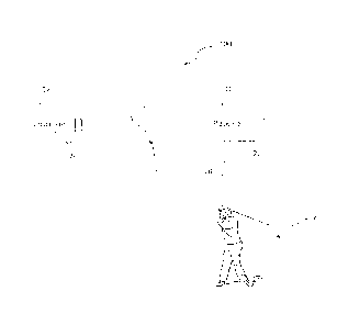
73 Figure 5 is a perspective view in partially schematic form
24 representative of a user and the training assembly of the
embodiment of Figures 1 through 3 mounted thereon, where in the
11
CA 02874889 2014-12-11
1 user has reached the "reactive segment" of the swing motion.
2
Figure 6 is a schematic representation of a mechanical impulse
3 generator associated with the receiver of the embodiment of Figures
4 1-4.
Like reference numerals refer to like parts throughout the
6 several views of the drawings.
7
S DETAILED DESCRIPTION OF THE PREFERRED EMBODIMENT
9 The
various preferred embodiments of the present invention are
represented in Figures 1 through 6. More specifically the training
11 assembly is generally indicated as 100 and is further represented
12 as being used with an individual, user or player generally
13 indicated as 102. The training assembly 100 is structured to
14
facilitate the performance of a proper swing motion, perhaps best
represented in Figure 5, such as used in the practicing or
16 performance of a sports activity. As also indicated herein, many
17 sports activities involve the performance of a proper "swing
18 motion" including but not limited to the game of golf. For purposes
19 of clarity the training assembly 100 of the present invention will
be primarily demonstrated and described with reference to a "swing
21 motion" used in the game of golf. However the versatility and
22 operative features of the training assembly 100 is capable of being
23 used in the performance and training of swing motions associated
24 with other sports including baseball, hockey, lacrosse, and/or
other activities which incorporates the use of a sports club.
12
CA 02874889 2014-12-11
1 However, the training assembly 100 is not limited to the training
2 or facilitation of a swing motion of an individual utilizing an
3 appropriate sports club. Accordingly, the term "swing motion" is
4 also used to describe an individual involved in a throwing motion,
such as when throwing a ball or like object.
6
Accordingly, one or more preferred embodiments of the training
7 assembly 100 facilitate the performance of a preferred swing motion
= 8 by indicating to the user or player 102 when a "reactive segment"
9 of the swing motion has been reached. The indication of the
reactive segment to the player 102 is for the purpose of informing
11
the player 102 when the hips, generally indicated as 104 should be
12 rotated, moved or properly positioned to accommodate and facilitate
= 13 a proper or preferred swing motion, dependent upon the specific
14 sports or other activity being performed by the player 102.
As schematically represented in the Figures 1-5, the training
16 assembly 100 includes a receiver 10 and a transmitter 12. As also
17 shown throughout the Figures, the receiver 10 is located within a
18 first predetermined vicinity relative to the user or player 102
19 such as, but not limited to being mounted directly on the player
102. In addition, the transmitter 12 is operatively located within
21 a second predetermined vicinity relative to the player 102 and
22 receiver 10. The second predetermined vicinity may be defined by
23 the transmitter being mounted on the player 102 or being located
24 remotely therefrom as schematically represented in Figure 4, to be
described in greater detail hereinafter.
13
CA 02874889 2014-12-11
1
The receiver 10 in the transmitter 12 are cooperatively
2 structured for wireless communication with one another. As
3 represented in Figure 1, the transmitter 12 is structured to
4 generate and wirelessly transmit an activating signal 14 to the
receiver 10 upon a predetermined distance 16 (see Figure 3)
6 existing between the receiver 10 and transmitter 12. Upon receipt
7 of the activating signal 14, the receiver 10 is structured to
8 transmit and communicate an indicating signal 18 to the user 102.
9 The indicating signal 18 is operative to inform the user 102 when
the hip rotation or hip movement should be instigated, based on the
= 11 fact that the "reactive segment" of the swing has been reached by
12 the transmitter 12. The indicating signal 18 being transmitted to
13 the user 102 during a "reactive segment" of the swing motion will
14 be explained in greater detail with reference to Figure 5. Also,
the form or configuration of the indicating signal 14 may vary
= 16 dependent, at least in part, first and second predetermined
17 vicinities or relative positions or locations of the receiver 10
18 and transmitter 12. In more specific terms the relative location
19 between the receiver 10 and transmitter 12 may be determinative of
the form or configuration of the indicating signal, generated by
21 the receiver 10.
2/
Accordingly, one preferred embodiment of the present
23 invention, is represented in Figures 1-3 and 5 and includes a first
24 predetermined vicinity defined by the receiver 10 being mounted on
the user. Preferably the receiver 10 is disposed at a predetermined
14
CA 02874889 2014-12-11
1 location such as adjacent a selected hip 104'. When the receiver 10
2 is so mounted, the indicating signal 18 may be in the form of a
3 generated sound of sufficient loudness to be easily heard during
4 the performance of the swing motion by the user 102. As indicated
herein, the indicating signal 18, being in the form of a generated
6 sound, is generated and delivered during the "reactive segment" of
7 the swing motion. In contrast, the indicating signal 18 may also
8 comprise a mechanical impulse such as, but not limited to, a
= 9 vibration applied directly to the user 102, such as about the hip
104'. Such a mechanical impulse will serve to inform the user that
11 the "reactive segment" of the swing motion has been reached and
12 that rotation or other intended movement of the hips 104 should be
13 instigated by the user 102.
=
14 The receiver 10 may include a variety of different wireless
communication devices specifically including, but not limited to, a
16 wireless mobile communication device such as a cell phone, smart
17 phone, etc. As such, the mobile communication device may be
18 preprogrammed to generate the aforementioned indicating signal 18
19 in the form of the generated sound and or mechanical vibration. As
further indicated, either the sound heard by the player 102 or the
21 mechanical vibration felt by the player 102 informs the player 102
22 that the reactive segment of the swing motion has been reached. As
23 explained in greater detail hereinafter, determination of the
24 "reactive segment" of the swing will be based on the transmitter 12
being located a predetermined, preprogrammed distance from the
= CA 02874889 2014-12-11
1 receiver 10, as it travels with the arm or wrist of the user 102
2 during the swing motion.
3 As another representative embodiment of the training assembly
4 100, the receiver 10 may include or be operatively associated with
an impulse generator 110 disposed in direct confronting and or
6 engaging relation to a portion of the body of the user 102, such as
7 adjacent either of the hips 104', as schematically represented in
8 Figure 6. Moreover, the impulse generator 110 may be in the form of
9 an electrical impulse generator, disposed in electrically
conductive relation to a predetermined portion or hip 104' of the
11 player 102. As such, an electric charge or electric shock is
12 delivered to the body or hip portion 104'. Alternatively, the
13 impulse generator 110' may be structured to deliver a mechanical
14 impulse and be in the form of a mechanical impulse generator. The
mechanical impulse generator 110' may be in the form of a spring-
16 loaded device 112 having a plunger 114 which is "triggered" when
17 the receiver 10 receives the activating signal 14 from the
= 18 transmitter 12. The plunger 114 will be forced outwardly into
19 mechanical engaging relation with a corresponding body portion 104'
of the hips 104 or other portion of the player's body.
21 In the schematically represented embodiments of Figures 1-3
22 and 5 both the receiver 10 and the transmitter 12 are mounted on
= 23 the player 102 such as adjacent the hip 104 and arm or wrist 106
24 respectively. Accordingly, both the first predetermined vicinity
and the second predetermined vicinity may be defined by the
16
CA 02874889 2014-12-11
1 receiver 10 in the transmitter 12 both being mounted on
2 predetermined body portions of the player 102. Therefore, during
3 the performance of the swing motion, as best represented in figure
4 5, the transmitter 12 will be continuously moved a greater distance
from the receiver 10 as it moves with the arm 106 as the player 102
6 goes through the swing motion. It is again emphasized that the
7 swing as represented in Figure 5 represents a golf swing. As such,
8 the player 102 is represented during the swing motion and at the
9 top of the backswing. The increase in distance and or the specific
distance between the receiver 10 and the transmitter 12 is
11 generally indicated as 113. The distance 113 will be preprogrammed
12 or preset and as a result will be recognized by a "proximity
13 determining assembly" 22, 24. In the embodiment of Figure 1, the
14 proximity determining assembly may comprise proximity sensitive
RFID tags 22 and 24 located respectively on the receiver 10 and the
16 transmitter 12. The RFID tags 22 and 24 or other distance
17 determining components defining the proximity determining assembly
18 may be preprogrammed and/or adjusted to recognize a predetermined
19 separation distance 113 between the receiver 10 and the transmitter
12 which coincides with the "reactive segment" 120 of the swing
21 motion, as generally represented in Figure 5. Upon reaching the
22 reactive segment 120, the transmitter 12 will be triggered to
23 generate and wirelessly deliver the activating signal 14 to the
24 receiver 10. Upon receipt of the activating signal 14, the receiver
10 will be activated to generate and deliver the indicating signal
17
=
CA 02874889 2014-12-11
1 18 directly to the player 102. The player 102 will then know to
2 activate a "complementary adjustment" in his or her swing motion.
3 The "complementary adjustment" as used herein is defined as the
4 proper and timely movement or rotation of the hips 104, during the
performance of the swing motion.
6 As
schematically represented in Figures 2, 3 and 5, the
7 receiver is indicated as being located on the left hip 104' of the
8 user 102, while the transmitter 10 is represented as being located
9 on the right hand of the user 102. However, it is emphasized that
the transmitter 10 and the receiver 12 can be located on the same
11
side of the user, or different sides of the user 102. For example
12 and in addition to the representations of Figures 2, 3 and 5, when
13 a right-handed user 102 has the transmitter 12 mounted on or
14 connected to the right-hand or other portion on the right side of
his/her body, it may be more comfortable or functionally expedient
16 to place the receiver 10 on the corresponding, right hip 104'.
= 17 Similarly, when the transmitter 12 is mounted on a left-hand or
18
other left side portion of a left-handed user 102, placement of the
19 receiver 10 on the left hip 104' may be more comfortable or
functionally expedient.
21
The versatility of the training assembly 100 is further
= 22 demonstrated in the additional preferred embodiment of Figure 4.
23
More specifically, the first predetermined vicinity of the receiver
24 10
may be defined by it being mounted on an appropriate portion of
the player 102 as represented. However, in contrast, the
18
CA 02874889 2014-12-11
1 transmitter 12' will be located remote from the player 102 in
2 operative relation by a second individual 103 which may be
3 representative of a "swing coach". As such, the individual 103
4 observes the swing motion of the player 102. When the swing motion
enters or reaches the reactive segment 120, (Figure 5) the swing
6 coach or other individual 103 will manually activate the
7 transmitter 12' causing the activating signal 14' to be delivered
8 to the receiver 10 from the transmitter 10' from the remote
9 location. As with the above noted embodiments, the form or
= 10 configuration of the indicating signal 14' may be in the form of a
11
generated sound, a mechanical vibration, a mechanical impulse, etc.
12
While not specifically represented in the Figures both the
13 receiver 10 and the transmitter 12 may include appropriate
14 attachment or connecting structures such as belts, straps,
= 15 harnesses, etc. dimensioned and configured to position the receiver
16 10 and the transmitter 12 in appropriate locations on the player's
17 body 102 as set forth in detail above.
18
Since many modifications, variations and changes in detail can
19 be made to the described preferred embodiment of the invention, it
20 is intended that all matters in the foregoing description and shown
21
in the accompanying drawings be interpreted as illustrative and not
22 in a limiting sense. Thus, the scope of the invention should be
23 determined by the appended claims and their legal equivalents.
24 Now that the invention has been described,
19