Note: Descriptions are shown in the official language in which they were submitted.
CA 02875442 2016-03-11
TITLE OF THE INVENTION
Method for Separating Portions of a Food Mass
FIELD OF THE INVENTION
The invention relates to a method and a device for separating portions of a
food
mass from a film tube, which is continuously advanced along a tube-conveying
path
at belt-running speed and is filled with the food mass, in particular with
processed
cheese, wherein the film tube filled with the food mass is initially formed
into a band
of defined thickness by means of a pair of calibrating rollers and wherein, in
order to
form separate food portions, the food mass is then displaced, by means of a
pair of
displacement rollers acting upon one another, out of displacement regions
extending
transversely across the film tube. A transverse sealing for closing the
individual
slices is subsequently implemented in the displacement regions. Finally, the
individual slices are separated from the chain by means of cuts in the
transverse
seal.
BACKGROUND OF THE INVENTION
Such methods have been known for a long time from the production of
individually
packaged processed-cheese slices ("IWS", "individual wrapped slices") and are
described, for example, in DE 42 04 357 Al and US 5,112,632. According
thereto, a
film tube is initially formed from a film and is sealed on the longitudinal
seam. This
film tube is filled with the food mass and is initially rolled to form a band.
The food
mass is separated into individual portions by displacement, either in the
state while
still hot ("hot displacement") or in the cooled state ("cold displacement").
The
displacement regions are subsequently closed in a sealing manner by means of a
transverse sealing tool and are finally cut into individual portions.
The displacement tool either has two displacement belts, which move in
synchronism when in contact with the product tube, or a plurality of
displacement
rollers, wherein displacement belts or displacement rollers are provided with
displacement webs, by means of which the displacement pressure is applied onto
the filled tube. The displacement webs roll on the film tube during
displacement. As
is known, the displacement tools are operated at a peripheral speed that is
constant
and, above all, is synchronized with the belt-running speed by means of
mechanical
coupling. The geometry of the displacement tool and of the displacement webs
therefore must be adapted to the size of the food slices to be produced.
CA 02875442 2016-03-11
In the known displacement tools, the separation between the displacement webs
defines the separation between the displacement regions. In these devices, it
is
either not possible, or is made possible only with a great deal of
retrofitting, to
change the slice size in the cheese-band running direction or to spontaneously
adjust the slice size in accordance with changes in the production parameters.
In the
fixed correlation of belt-running speed and transverse displacement, it is
also
possible to react only in a mechanical manner to process-related changes, for
example, to a lengthening of the film. Such a mechanical adjustment is complex
and
entirely inflexible, however.
Such a device is also disclosed, for example, in DE 196 20 560. In this case
as well,
the size of the slices is predetermined by a displacement station having
displacement webs disposed at fixed intervals on a belt. Due to the fixed
separation
between the displacement regions, a correlation of all downstream rollers,
which are
equipped with tools engaging into the displacement regions, with the belt
speed is
absolutely necessary.
SUMMARY OF THE INVENTION
The problem addressed by some embodiments of the present invention is
therefore that
of providing a method for portioning a food mass in a film tube, which is
continuously
advanced along a tube-conveying path and is filled with food mass, which can
have a
simple design and can offer a great deal of flexibility in terms of making the
transverse
displacement zone and, correspondingly, the transverse sealing. A further
problem
addressed is that of trying to create a simply and cost-effectively designed
device for
implementing the method, which can produce differently spaced displacement
regions
and, therefore, variable packaging sizes using the same displacement tool.
In some embodiments of the present invention, there is provided a method for
separating
portions of a food mass from a film tube, which is continuously advanced along
a tube-
conveying path at a continuous belt-running speed and is filled with the food
mass, in
particular with processed cheese, wherein the film tube filled with the food
mass is initially
formed into a band of defined thickness by means of a pair of calibrating
rollers, and
wherein, in order to form separate food portions, the food mass is then
displaced, by
2
CA 02875442 2016-03-11
means of a pair of displacement rollers having displacement webs acting upon
one
another, out of displacement regions extending transversely across the film
tube,
characterized in that
the displacement rollers are driven by means of a drive, which is controllable
in terms of
the running thereof, in a manner decoupled from the continuous belt-running
speed.
In some embodiments of the present invention, there can be provided the method
described herein, characterized in that the displacement rollers are
controlled with
specifiable rotation characteristics by means of a computer program, which
implements
timing.
In some embodiments of the present invention, there can be provided the method
described herein, characterized in that the displacement rollers are
controlled by means
of a computer program in correlation with a sensor signal, wherein the sensor
signal
correlates with a detectable pattern on the film tube.
In some embodiments of the present invention, there can be provided the method
described herein, characterized by the following method steps of:
detecting a defined part of a pattern provided on the film tube, in particular
a pattern mark,
by means of a sensor,
operating the displacement rollers in a manner dependent on the detection of
the defined
part of the pattern such that the food mass is displaced out of the film tube
in a
displacement region at a predetermined distance from the defined part of the
pattern,
In some embodiments of the present invention, there can be provided the method
described herein, characterized in that, on the basis of the position of the
defined part
along the tube-conveying path and on the basis of the time of the detection of
the mark, a
displacement time is determined, at which the displacement rollers, with the
displacement
webs thereof, are brought into displacing contact with the tube.
In some embodiments of the present invention, there can be provided the method
described herein, characterized in that a transverse sealing seam is produced
in the
displacement region after the food mass was displaced out of the displacement
region.
2a
CA 02875442 2016-03-11
In some embodiments of the present invention, there can be provided the method
described herein, characterized in that a contour cut on a longitudinal edge
of a film, which
forms the film tube, for forming tear-open tabs on the finished package is
synchronized,
at least indirectly, with the displacement rollers and/or the transverse
sealing rollers.
In some embodiments of the present invention, there is provided a device for
separating
portions of a food from a film tube, which is continuously advanced along a
tube-conveying
path and is filled with a food mass, in particular with processed cheese,
wherein, in order
to form separate food portions, displacement rollers are provided for
displacing the food
mass out of a displacement region,
characterized by
a drive, which is controllable in terms of the running thereof, in particular
a stepper motor
or a servo drive, provided for a drive of the displacement rollers that is
decoupled from a
continuous belt-running speed.
In some embodiments of the present invention, there can be provided the device
described herein, characterized by a computer program for controlling the
displacement
rollers in correlation with a sensor signal and/or in correlation with a
timing.
In some embodiments of the present invention, there can be provided the device
described herein, characterized by
means, in particular conveyor belts, for guiding the film tube along a tube-
conveying path,
a sensor for detecting a defined part of an embossed or printed pattern, in
particular a
pattern mark, on the film tube, or of a recess in the film tube, a controller
for controlling
the servo drive in a manner dependent on a signal generated by the sensor in
order to
displace the food mass out of the film tube at a predetermined distance from
the defined
part of the printed pattern or the recess.
In some embodiments of the present invention, there is provided a method for
separating
portions of a food mass from a film tube, the film tube being continuously
advanced along
a tube-conveying path at a continuous belt-running speed and being filled with
the food
mass, the method comprising:
forming the film tube filled with the food mass initially into a band of
defined
thickness by means of a pair of calibrating rollers; and
2b
CA 02875442 2016-03-11
in order to form separate food portions, displacing the food mass by means of
a
pair of displacement rollers having displacement webs acting upon one another,
out of a
displacement region extending transversely across the film tube,
wherein the displacement rollers are driven by means of a drive, and
wherein running of the drive is controllable in a manner decoupled from the
continuous belt-running speed.
In some embodiments of the present invention, there is provided a device for
separating
portions of a food from a film tube, which is continuously advanced along a
tube-conveying
path at a continuous belt-running speed and is filled with a food mass, the
device
comprising:
displacement rollers for displacing the food mass out of a displacement
region, in
order to form separate food portions; and
a drive for driving the displacement rollers,
wherein running of the drive is controllable in a manner that is decoupled
from the
continuous belt-running speed.
A significant fundamental idea of some of the embodiments of the invention
initially relates
to the decoupling of the transverse displacement procedure and the transverse
sealing
procedure from the belt-running speed. This is achieved according to the
invention by
virtue of the fact that the displacement rollers, which, in one advantageous
embodiment,
also implement the transverse sealing, are driven in a manner decoupled from
the belt-
2c
CA 02875442 2014-12-02
running speed and, therefore, are driven in any functional interrelationship
therewith
by means of a drive, which is controllable in terms of the running thereof, in
particular
in terms of the angle of rotation and the speed of rotation. Such a drive can
be
implemented by means of stepper motors or by servo motors. Whereas, in a
stepper
motor, the field rotates in a stepped manner and the shaft moves accordingly
in
defined individual steps, the position, speed and/or torque of the servo drive
is
controlled by means of a closed-loop control system. The invention makes use
of the
fact that such motors can be used to set any motion profile independently of
external
factors, and that the motion profile can also be set with any dependencies on
external parameters, which are due to sensors, in particular. Given that a
decoupling
of the transverse displacement procedure and of the transverse sealing
procedure
takes place, these steps can be adjusted in any way relative to the
advantageously
continuous belt-running speed. It must ensured, of course, that the transverse
displacement and the transverse sealing correlate to the extent that sealing
must
also be carried out in the displacement regions, which, in the simplest case,
can take
place quasi simultaneously by means of a combination of a transverse
displacement
roller and a transverse sealing roller.
At this point, it is emphasized that the feature "roller" also refers to
rollers, in the
following, that are guided by means of a belt. A displacement roller can
therefore
also be formed by a smooth roller, by means of which a belt comprising
displacement webs is guided. A decisive point, however, is that only one
single pair
of displacement webs is ever engaged with the film tube filled with the food
mass,
thereby ensuring that any separation between the successive displacement
regions
can be implemented. A plurality of roller pairs disposed one behind the other
could
also be used for displacement.
By means of such drives it is possible to operate the displacement rollers
with a
dependency on the belt-running speed that is adjustable, but which is fixed
during
the production of a lot, or with predetermined, individual rotation
characteristics.
When these drives are used, each lot can be run with a different motion
profile, for
example, in order to produce slices having different dimensions; it is even
possible to
produce slices having different dimensions in the course of a lot. The
dimensions of
the slices to be produced can be programmed, in principle, in a fully flexible
manner
3
CA 02875442 2014-12-02
in advance using such drives, thereby ensuring that a program controls the
roller
drive and, therefore, the application of the displacement webs; in the
simplest case,
the application of the displacement webs is defined by a time period, which is
specified by the program and can be adjusted, thereby ensuring that the
displacement rollers can be controlled with specifiable rotation
characteristics by
means of a computer program that implements timing.
Rather than by means of such a time period, the displacement webs can also be
set
down under the control of sensors, which monitor the progress of the film
tube. By
means thereof, and by means of the separate drive, it is possible, in
particular, to
operate the displacement rollers in correlation with a detectable pattern on
the film
tube, i.e., to correlate the displacement with the actual belt advancement.
The
pattern can be printed on the film in the manner of a pattern mark
specifically for the
purpose of detection and synchronization. It can also be a distinctive point
in one
printed image in a series of recurrent images, which is used to implement
synchronization. Synchronization can also be implemented on the basis of
recurrent
recesses or impressions in the film that can be detected optically or by means
of
contact. In this embodiment, the displacement rollers are controlled in
correlation
with a sensor signal by means of a computer program, wherein the sensor signal
correlates with a detectable pattern on the film tube.
The synchronization with such a "mark" then comprises the following method
steps
of: detecting a defined part of a printed and/or embossed pattern, in
particular an
optically and/or tactilely detectable pattern mark, on the film tube by means
of a
sensor, which can be designed, in particular, as an optical and/or contact
sensor;
operating the (pair of) displacement rollers in a manner dependent on the
detection
of the defined part of the printed pattern such that the food mass is
displaced out of
the tube at a predetermined distance from the defined part of the printed
pattern.
According to the invention, the displacement and the subsequent sealing are
synchronized with the film printing or embossing, in particular with the
pattern mark,
and are implemented in the spaces between packages so as to be centered
between
pattern marks.
The idea, therefore, is that the function and the activity of the displacement
rollers
and, therefore, the displacement of the food mass itself is brought into
dependence
4
CA 02875442 2014-12-02
with that which is detected by the sensor. For example, the sensor detects the
pattern on the film tube, which is located at a previously defined distance
from the
displacement region. On the basis of the time and location of the pattern mark
upon
detection by the sensor, and on the basis of the conveyance speed of the film
tube, it
is now possible to determine the time at which the region of the film tube
where a
displacement should take place (the displacement region) will enter the active
region
of the displacement tool. The displacement rollers are then adjusted such that
the
displacement takes place exactly at this time (the displacement time). The
displacement rollers can be driven by a (stepper or) servo motor, in
particular, which
can bring the displacement rollers into an appropriate position exactly at the
displacement time. At the displacement time, it can also be ensured by the (?)
stepper motor that the peripheral speed of the displacement rollers
corresponds to
the conveyance speed of the tube. In the time period between two subsequent
displacement times, the displacement rollers can be brought to a higher or
lower
peripheral speed in order to compensate for differences between the separation
between two downstream displacement regions and between two downstream
displacement surfaces.
Further, on the basis of the above-described interaction, the function of the
displacement rollers can be brought at least indirectly into dependence with a
cut
pattern on the longitudinal edge of the film forming the tube. The cut pattern
can form
tear-open tabs on the finished package. The tear-open tabs should be centered
on a
cheese slice or on the exact package of a cheese slice, of course, which can
be
achieved by means of the method. The synchronization with the shape of the
film
can also be implemented on the basis of patterns that are not printed, which
also
applies to the entire invention. For example, the pattern can also be formed
by a
workpiece edge, e.g., a corner of the cut pattern, or the like.
The invention further comprises a device for separating portions of a food
from a film
tube, which is continuously advanced along a tube-conveying path and is filled
with a
food mass, in particular with a hot melted cheese, wherein, in order to form
separate
food portions, displacement rollers are provided for displacing the food mass
out of a
displacement region and. According to the invention, the device comprises a
drive,
which is controllable in terms of the running thereof, in particular a stepper
motor or a
CA 02875442 2016-03-11
servo drive, which permits a drive of the displacement rollers which is
decoupled
from the belt-running speed and correlates with a timing and/or a sensor
signal.
In one particularly advantageous embodiment of the invention, means are
provided
for guiding the film tube along the tube-conveying path, and a sensor is
provided for
detecting a defined part of an embossed or printed pattern, in particular a
pattern
mark, on the film tube, or of a recess in the film tube. The control of the
displacement
rollers is managed by a controller, which controls the displacement rollers in
a
manner dependent on a signal generated by the sensor such that the food mass
is
displaced out of the film tube at a predetermined distance from the defined
part of
the printed pattern or the recess.
BRIEF DESCRIPTION OF THE DRAWINGS
The invention is explained in greater detail in the following with reference,
wherein
Figure 1 shows a schematic depiction of a device for implementing the
method
according to the invention
a) in a top view, without a depiction of tools,
b) in a side view;
Figure 2 shows the course of the speed of a displacement roller for each of
the
cases, in which
a) the separation between two displacement surfaces is equal to the
separation between two displacement regions,
b) the separation between two displacement surfaces on the periphery
of the displacement roller is greater than the separation between two
displacement regions on the tube,
c) the separation between two displacement surfaces on the periphery
of the displacement roller is less than the separation between two
displacement regions on the tube;
Figure 3 a) shows the device according to figure la) with a product film
having a
contour cut on one side or both sides, on the longitudinai side of the
film,
6
CA 02875442 2016-03-11
b) shows a completed package having tear-open tabs, in the cross
section along the line of cut B-B according to figure 3a).
Figure 4 shows
a production device comprising a device for implementing the
method according to the invention.
DETAILED DESCRIPTION OF THE INVENTION
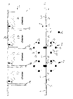
Figure 1 shows a film tube 1 during the method according to the invention. The
film
tube 1 is guided along a tube-conveying path 9 by non-illustrated guide means.
It is
filled with a processed-cheese mass 3, wherein the processed-cheese mass
packaged in the film tube is separated to form individually packaged slices.
At the
end of the method, individually packaged cheese slices of a certain size are,
wherein
any length of the slices can be set (even while the operation is underway) by
means
of the device according to the invention, but the width is predetermined by
the film
tube. In the present exemplary embodiment, every package is provided with an
image 14, which comprises a logo and product information in text form and is
centered exactly on the package.
Each image 14 has a pattern mark 5, which is detected by a sensor 6. A
displacement region 2 is defined at a defined distance from the pattern mark
5, onto
which displacement rollers 8, 12 are set in order to displace the processed
cheese
out of the displacement region 2. When the sensor 6 detects the pattern mark
5, the
displacement region 2 is located at a location x' at the time of the
detection. On the
basis of the constant conveyance speed v of the tube 1, it is then possible to
calculate a displacement time t" at which the displacement region 2 is
disposed at a
location x" along the conveyance path 9, at which a displacement is then
carried out
by means of the displacement rollers 12. The displacement surfaces 13 on the
displacement rollers 12 are moved toward one another by means of rotation and
pinch the film tube 1 there in order to displace the processed cheese 3 out of
the
displacement region 2. The processed cheese 2 is thereby portioned into
individual
cheese slices 4.
Next, the tube 1 is sealed in the region of the displacement region 2 by means
of a
transverse sealing tool 7 comprising transverse sealing rollers. The
individual slices
can be separated later by means of a transverse cutting in the sealed regions
2, for
example, by means of a device of the type described in WO 2008/119633 Al.
7
CA 02875442 2014-12-02
Therein, it is necessary that the displacement surfaces 13 be moved, at time
t" at
location x", at a peripheral speed u that correspond to the conveyance speed v
of the
tube 1. Figure 2a shows a speed diagram in which the peripheral speed u of the
displacement surfaces 13 is identical to the conveyance speed v. This is
possible
when the displacement regions 2 of the tube 1 have a separation between one
another that corresponds to the peripheral separation between two adjacent
displacement surfaces 13. The displacement surfaces 13 can then roll on the
tube at
a constant peripheral speed without sliding. It is assumed that the conveyance
speed
v of the tube 1 is constant.
If the separation between two adjacent displacement regions 2 is greater than
the
peripheral separation between two adjacent displacement surfaces 13, however,
the
speed of the displacement roller 12 must be reduced between the individual
displacement steps in order to prevent the displacement regions 2 from being
"outstripped" by the displacement surfaces 13. It is further provided,
however, that
the peripheral speed u of the displacement roller 12 still corresponds to the
conveyance speed v of the tube 1 during the displacement time t", in order to
1
prevent the tool 12 from sliding on the tube. The wave-shaped course shown in
figure 2b therefore results, which, on average, is less than the conveyance
speed of
the tube 1, however, and is implemented by the control of the servo motor 11.
For the case in which the separation between two adjacent displacement regions
2 is
less than the peripheral separation between two adjacent displacement surfaces
13,
the speed of the displacement roller 12 must be increased between the
individual
displacement steps in order to conversely prevent the displacement surfaces 13
from
being "outstripped" by the displacement regions 2. In this case as well, the
peripheral
speed u of the displacement roller 12 still corresponds to the conveyance
speed v of
the tube 1 during the displacement time t", in order to prevent the tool 12
from sliding
on the tube 1. The wave-shaped course shown in figure 2c therefore results,
which,
on average, is greater than the conveyance speed of the tube 1, however, and
is
implemented by the control of the servo motor 11. The downstream sealing
rollers 27
(figure 4) undergo a corresponding control at a another, corresponding, time
t'" and
at another location x".
8
CA 02875442 2014-12-02
Due to the invention, it is now possible to flexibly implement any separation
between
displacement regions 2 without the need to retrofit the device used for the
displacement. To this end, all that is required is either an adjustable timing
of the
displacement and sealing, or a pattern mark 5 is identified on the tube, which
is
detectable by a sensor and is always disposed at a predetermined distance from
the
desired displacement region. It is also possible, for example, to easily
switch to
different distances between the displacement regions 2 simply by changing the
timing and/or the distances between the pattern marks. A reliable
synchronization of
the displacement rollers 8 with the image printed on the tube or with other
markings,
in particular, is thereby achieved. It is hereby made possible for the first
time to
provide packages having exactly one processed-cheese slice with an image that
is
centered on the package.
A further possible application is explained with reference to figure 3. The
film forming
the tube 1 has a serrated pattern 15 on one or both longitudinal edges. In the
completed tube 1, the serrated pattern 15 then extends over the longitudinal
sealing
seam 17 such that tear-open tabs 16 extend beyond the longitudinal sealing
seam
17. The tear-open tabs 16 are fully exposed and can be gripped individually by
the
end user and pulled apart from one another in order to open the package. The
pattern mark 5 is synchronized with the serrated pattern 15. One cheese slice
4 is
therefore separated out of the processed-cheese mass 3 by means of the
synchronization of the displacement rollers 8 with the pattern mark 5, which
is
oriented with respect to the serrated pattern 15 and, therefore, the tear-open
tabs 16.
It is not necessary for the displacement rollers 8 and the transverse sealing
tool 7 to
act across the entire width of the film and can, instead, omit the region of
the tear-
open tabs 16.
Figure 4 shows a schematic depiction of a production line 18 for producing
individually packaged cheese slices, which is suitable for the device of the
method
according to the invention. Melted, flowable processed cheese 3 is supplied
via a
supply nozzle 19 in the upper region. At a shaped projection 20, tube film 21,
which
is still flat when initially advanced, is wrapped around the supply nozzle 19
in a "U"
shape. The longitudinal edges of the tube film, which come to lie one on top
of the
other due to V-shaped arrangement, are sealed in a downstream longitudinal
sealing
9
CA 02875442 2014-12-02
unit 22, thereby producing the continuous longitudinal sealing edge 17 (figure
1a).
The film tube 1 is thereby produced.
Downstream thereof, the film tube 1 filled with processed cheese 3 passes two
oppositely rotating calibration rollers 23, by means of which the slice
thickness of the
processed-cheese slices 4 is set. Two downstream conveyor belts 24 clamp the
filled film tube 1 between themselves. By means of a tension force, which the
conveyor belts 24 apply onto the film tube, said film tube is held taut in the
region
above the conveyor belts 24 and is conveyed further downward. In another
embodiment, the conveyor belts 24 can also be mounted underneath the
displacement and sealing tools. The conveyor belts 24 ensure that the film
tube 1 is
brought to a desired conveyance speed, which is a necessary prerequisite for
the
function of the displacement rollers. An optical sensor 6 detects the pattern
marks or
other patterns on the film tube 1.
The displacement rollers are provided downstream of the conveyor belts 24. In
this
case, in deviation from the exemplary embodiment according to figure 1, these
are
embodied as three successively disposed pairs of ribbed conveyor belts 25,
which
are provided with webs 26 oriented transversely to the conveyance direction.
The
webs 26 form the displacement surfaces 9 in a manner analogous to the
displacement rollers 12 according to figure 1 and can likewise displace
processed-
cheese mass 3 out of the regions of the tube 1. During the displacement, the
webs
26 are operated at the peripheral speed u, which corresponds to the conveyance
speed v of the tube. Two pairs of transverse sealing rollers 27 are provided
downstream thereof, in the conveyance direction, which transversely seal the
tube
film in the displacement regions 2. The function of the ribbed conveyor belts
25 and
the transverse sealing rollers 27 is analogous to the function of the
corresponding
elements of the exemplary embodiment according to figure 1 and figure 2. Next,
the
tube 1 passes through a cooling water bath 28, thereby cooling the newly
formed
individual slices of processed cheese.
The two method steps are synchronized with a printed and/or embossed surface
due
to the use of the displacement and sealing centered with respect to the
pattern mark
(or centered with respect to another mark). It is therefore possible to place
the
displacement and the transverse sealing so as to be centered between the
printed
CA 02875442 2015-01-30
images. Synchronization with the image printed on the film is therefore
possible due
to the drive of the displacement and transverse sealing tools according to the
invention. The drive further makes it possible to switch to any slice lengths
within a
specified range, even during the operation, without changing tools, which is
suitable,
in particular, for films that are unprinted or are printed by means of scatter
printing.
The device according to figure 1 can be easily installed in the production
device
described herein, as a replacement for corresponding units shown in figure 4.
CA 02875442 2014-12-02
List of reference signs
1 tube
2 displacement region
3 processed cheese
4 cheese slice
pattern mark
6 sensor
7 transverse sealing tool
8 displacement tool
9 tube-conveying path
transverse sealing seam
11 stepper motor
12 displacement roller
13 displacement surface
14 image
serrated pattern
16 tear-open tab
17 longitudinal sealing seam
18 production machine
19 supply nozzle
shaped projection
12
CA 02875442 2014-12-02
21 tube film
22 longitudinal sealing unit
23 rollers for calibration
24 conveyor belts
25 ribbed conveyor belts
26 webs
27 transverse sealing rollers
28 cooling water bath
= position along the tube-conveying path
time
= conveyance speed of the tube
= peripheral speed of the displacement surfaces
13