Note: Descriptions are shown in the official language in which they were submitted.
CA 02875657 2014-12-03
WO 2013/184656
PCT/US2013/044068
BLOW DOWN ACTUATOR ASSEMBLY
FIELD OF THE INVENTION
[0001] The present invention relates to actuator mechanisms, more particularly
to an
actuator assembly having an integrated emergency backup system.
BACKGROUND OF THE INVENTION
[0002] Mechanical linear actuators are used for translating rotational motion
to linear
motion. For example, ball screws arc linear actuators that rely on a threaded
shaft and a nut
housing. The nut housing typically contains ball bearings that engage a
helical raceway
defined by the threaded shaft. Thus, rotational movement of the shaft
translates into linear
movement of the nut housing along the shaft. These types of linear actuators
are often used
in aeronautical applications, for example, to control movement of control
surfaces, open and
close windows, doors and/or access panels, and control the extension of
landing gear. Linear
actuators are also often used to convert rotary motion from an electric motor
to axial
movement of a steering rack in vehicular power steering systems and for
precision control in
robotic manufacturing.
[0003] Particularly in aeronautical applications, the failure of a mechanical
linear
drive system can have catastrophic consequences. The failure of one or more
aspects of the
drive system, such as the motor, the gear train, or the ball screw drive, may
result, for
example, in the landing gear of an airplane failing to extend or to extend
into a fully locked
open position. Accordingly, emergency systems are often provided that override
and/or
bypass the mechanical linear drive system to address such failures. However,
these systems
are often separate assemblies from the drive assembly, requiring additional
space and
hardware to accommodate the assembly. There is a need and desire for an
actuator assembly
¨ 1 ¨
that has an integrated emergency system, a system that automatically decouples
aspects
of the system from the normal drive configuration during an emergency.
SUMMARY
According to a broad aspect, there is provided an actuation member comprising
a
drive arm assembly;
a release member;
a source of pressurized gas;
a securing mechanism, wherein the securing mechanism releasably locks the
actuation member to the release member during a normal mode of operation;
a drive assembly comprising a cover tube having an end cap and a seal plug;
the drive arm assembly being configured to extend from the end cap;
the securing mechanism comprising an expandable retention ring housed toward a
distal end of the cover tube, wherein the actuation member includes a
circumferential
retention groove, the expandable retention ring being biased to compress into
the
retention groove when the actuation member extends a predetermined distance
from the
end cap of the cover tube; and
a nut adapter coupled to a ball nut and the release member, the nut adapter
being
configured with a release mechanism for expanding the expandable retention
ring when
the release member is secured to the actuation member, wherein the expandable
retention
ring comprises at least two arcuate sections;
wherein during the normal mode of operation, the actuation member and the
release member are engaged to move in unison; and
wherein during an emergency mode of operation, a pressurized gas automatically
decouples the actuation member from the release member to move separately.
[0004] Embodiments of the present invention advantageously provide an
actuation assembly and methods of use thereof. A preferred embodiment of an
actuator
assembly includes an actuation member, a release member, and a source of
pressurized
gas, wherein during a normal mode of operation, the actuation member and the
release
member are engaged to move in unison, and wherein during an emergency mode of
- 2 -
CA 2875657 2019-07-23
operation, pressurized gas automatically decouples the actuation member from
the release
member to move separately.
According to another broad aspect, there is provided an electro-mechanical
actuator comprising:
an electro-mechanical drive system that comprises an actuation member, a drive
assembly, and a release member;
the actuation member comprising a drive arm assembly;
the drive assembly comprising a cover tube having an end cap and a seal plug;
the drive arm assembly being configured to extend from the end cap;
an integrated backup system operated by a pressurized gas and the integrated
backup system comprising a securing mechanism; and
the securing mechanism comprising an expandable retention ring housed toward a
distal end of the cover tube,
wherein during a normal mode of operation, the actuation member and the
release
member are engaged with the securing mechanism to move in unison to extend a
controlled member to a predetermined position; and
wherein, when the integrated backup system is activated during an emergency
mode of operation, the electro-mechanical drive system is decoupled such that
the
actuation member and the release member move separately in order for the
actuation
member to extend the controlled member to the predetermined position and the
securing
mechanism mechanically locks the controlled member in the predetermined
position.
Variants, examples and preferred embodiments of the assembly are described
hereinbelow in the detailed description section.
[0005] In accordance with yet other aspects of the present disclosure, an
electro-
mechanical actuator includes an electro-mechanical drive system and an
integrated
backup system operated by a gas generator, wherein when the backup system is
activated,
the electro-mechanical drive system is decoupled and the actuator moves to a
predetermined position and mechanically locks in place.
[0006] There has thus been outlined, rather broadly, certain embodiments of
the
invention in order that the detailed description thereof may be better
understood, and in
order that the present contribution to the art may be better appreciated.
There are, of
- 2a -
CA 2875657 2019-07-23
course, additional embodiments of the invention that will be described below
and which
will form the subject matter of the claims appended hereto.
[0007] In this respect, before explaining at least one embodiment of the
invention in detail, it is to be understood that the invention is not limited
in its
application to the details of construction and to the arrangements of the
components set forth in the following description or illustrated in the
drawings.
The invention is capable of embodiments in addition to those described and of
being practiced and carried out in various ways. Also, it is to be understood
- 2b -
CA 2875657 2019-07-23
CA 02875657 2014-12-03
WO 2013/184656
PCT/US2013/044068
that the phraseology and terminology employed herein, as well as the abstract,
are for the
purpose of description and should not be regarded as limiting.
[0008] As such, those skilled in the art will appreciate that the conception
upon which
this disclosure is based may readily be utilized as a basis for the designing
of other structures,
methods and systems for carrying out the several purposes of the present
invention. It is
important, therefore, that the claims be regarded as including such equivalent
constructions
insofar as they do not depart from the spirit and scope of the present
invention.
BRIEF DESCRIPTION OF THE DRAWINGS
[0009] The accompanying drawings, which are incorporated in and constitute a
part
of this specification, illustrate various embodiments consistent with the
invention, and,
together with the description, serve to explain the principles of the
invention.
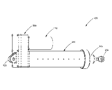
[0010] FIG. 1 is a front perspective view of a blow down actuator assembly, in
accordance with certain aspects of the present invention;
[0011] FIG. 2 is a another perspective view of a blow down actuator assembly,
in
accordance with certain aspects of the present invention;
[0012] FIG. 3 is a side view of a blow down actuator assembly, in accordance
with
certain aspects of the present invention;
[0013] FIG. 4 is a cross-sectional view of the blow down actuator assembly as
seen
along line A-A in FIG. 3, in accordance with certain aspects of the present
invention;
[0014] FIG. 5 is a front perspective view of a blow down actuator assembly
with a
cover tube and gear housing removed to illustrate internal components of the
assembly, in
accordance with certain aspects of the present invention;
[0015] FIG. 6 is a front perspective view of a blow down actuator assembly
with a
cover tube and gear housing removed and with the drive arm assembly in an
extended
position of use, in accordance with certain aspects of the present invention;
¨3¨
CA 02875657 2014-12-03
WO 2013/184656
PCT/US2013/044068
[0016] FIG. 7 is a cutaway front view of a blow down actuator assembly, in
accordance with certain aspects of the present invention;
[0017] FIG. 8 is a close-up cutaway view of aspects of a blow down actuator
assembly, in accordance with certain aspects of the present invention;
[0018] FIGS. 9-11 illustrate in series a locking ring mechanism for use on a
blow
down actuator assembly, in accordance with certain aspects of the present
invention;
[0019] FIG. 12 is a cutaway front view of a blow down actuator assembly in an
emergency mode of operation, in accordance with certain aspects of the present
invention;
[0020] FIG. 13 is a cutaway front view of a blow down actuator assembly in an
emergency mode of operation fully extended and mechanically locked, in
accordance with
certain aspects of the present invention;
[0021] FIG. 14 is a perspective view of a blow down actuator assembly, in
accordance with certain aspects of the present invention;
[0022] FIG. 15 is a cutaway front view of the blow down actuator assembly
shown in
FIG. 14, in accordance with certain aspects of the present invention;
[0023] FIG. 16 is a front perspective view of the blow down actuator assembly
shown
in FIG. 14 with a cover tube and gear housing removed to illustrate internal
components of
the assembly, in accordance with certain aspects of the present invention;
[0024] FIG. 17 is a front perspective view of the blow down actuator assembly
shown
in FIG. 14 with a cover tube and gear housing removed and with the drive arm
assembly in
an extended position of use, in accordance with certain aspects of the present
invention;
[0025] FIG. 18 is a close-up cutaway view of aspects of the blow down actuator
assembly shown in FIG. 14, in accordance with certain aspects of the present
invention;
[0026] FIG. 19 is a front cutaway view of aspects of the blow down actuator
assembly shown in FIG. 14, in accordance with certain aspects of the present
invention;
¨4¨
CA 02875657 2014-12-03
WO 2013/184656
PCT/US2013/044068
[0027] FIGS. 20 and 21 illustrate in series a securing mechanism for use on a
blow
down actuator assembly, in accordance with certain aspects of the present
invention;
[0028] FIG. 22 is a cutaway front view of the blow down actuator assembly
shown in
FIG. 14 with a cover tube removed to illustrate internal components in an
emergency mode
of operation, in accordance with certain aspects of the present invention;
[0029] FIG. 23 is a close-up cutaway perspective view with a cover tube
removed to
illustrate internal components of the blow down actuator assembly shown in
FIG. 14 in an
emergency mode of operation, in accordance with certain aspects of the present
invention;
and
[0030] FIGS. 24 to 26 illustrate in series the blow down actuator assembly
shown in
FIG. 14 with a cover tube removed to illustrate a reengagement procedure
following an
emergency procedure, in accordance with certain aspects of the present
invention.
DETAILED DESCRIPTION
[0031] The invention will now be described with reference to the drawing
figures, in
which like reference numerals refer to like parts throughout.
[0032] Various aspects of an actuator assembly may be illustrated by
describing
components that arc coupled, attached, and/or joined together. As used herein,
the terms
"coupled", "attached", and/or "joined" are used to indicate either a direct
connection between
two components or, where appropriate, an indirect connection to one another
through
intervening or intermediate components. In contrast, when a component is
referred to as
being "directly coupled", "directly attached", and/or "directly joined" to
another component,
there are no intervening elements present.
[0033] Relative terms such as "lower" or "bottom" and "upper" or "top" may be
used
herein to describe one element's relationship to another element illustrated
in the drawings.
It will be understood that relative terms are intended to encompass different
orientations of an
¨5¨
CA 02875657 2014-12-03
WO 2013/184656
PCT/US2013/044068
electric strike assembly in addition to the orientation depicted in the
drawings. By way of
example, if aspects of an actuator assembly shown in the drawings are turned
over, elements
described as being on the "bottom" side of the other elements would then be
oriented on the
"top" side of the other elements. The term "bottom" can therefore encompass
both an
orientation of "bottom" and "top" depending on the particular orientation of
the apparatus.
[0034] FIGS. 1 - 4 illustrate multiple views of an assembled blow down
actuator
assembly 100 in accordance with aspects of the present invention. The actuator
assembly
100 may include an electric motor 110 operably connected to a drive assembly
200 via a gear
train housed in a gear housing 300. A mounting device 120, such as a bracket
or any other
suitable mounting mechanism, may be provided on a surface of the gear housing
300 for
mounting the actuator assembly 100 to a stable support structure, such as the
body structure
of an airplane. The drive assembly 200 includes a drive arm assembly 202 for
actuation of a
controlled member, such as a control surface, door or a landing gear, for
example. A distal
end of the drive arm assembly 202 may be provided with a connection device
204, such as an
eye bolt rod or any other suitable connection device, for connecting the drive
arm assembly
202 to the controlled member.
[0035] As shown in FIG. 2, the actuator assembly may be modular, wherein each
of
the major components, such as the motor 110 and the drive assembly 200, for
example, may
be separately and independently attached and/or detached from the gear housing
300 for ease
of maintenance and/or replacement. A motor mounting plate 112 and/or a drive
assembly
mounting plate 206 may be provided for mounting the motor 110 and the drive
assembly 200
to the gear housing 300 via attachment means, such as bolts or screws.
[0036] FIG. 3 is a side view of the actuator assembly shown in FIGs. 1 and 2.
FIG. 4
provides a cross-sectional view of the actuator assembly 100 taken along the
cross-sectional
plane A-A of FIG. 3. The motor 110 may have a central drive shaft 114 that is
operably
connected through gears 116 and 118 to drive a ball screw 208 of the drive
assembly 200.
¨6¨
CA 02875657 2014-12-03
WO 2013/184656
PCT/US2013/044068
The drive assembly 200 has a cover tube 210 and end cap 212. The end cap 212
has a central
orifice 214 through which the drive arm assembly 202 slidably extends. A ball
nut 216 may
be situated on the ball screw 208 such that, during normal operation of the
drive assembly
200, rotation of the ball screw 208 forces the ball nut 216 via housed
bearings 217 to travel
along the raceway defined by the threading on the ball screw 208. The
direction of rotation
of the ball screw 208 determines whether the drive arm assembly 202 extends or
retracts
through the orifice 214.
[0037] A nut adapter 218 may be provided on a distal end of the ball nut 216.
The
nut adapter 218 may be formed with one or more notched seats 220 for seating
one or more
end portions 222 of one or more release levers 224. The release levers 224 may
be rotatably
mounted on a release cap 226, as described in further detail below.
[0038] The release cap 226 may be fixed to an actuation tube 230, which is the
primary longitudinal body component of the piston-like drive arm assembly 202.
A release
tube 234 may be concentrically arranged inside of the actuation tube 230. A
locking ring 236
is provided that releasably engages the release tube 234 and the actuation
tube 230. The
release tube 234 extends longitudinally within the actuation tube 230 to abut
a release piston
238. The release piston 238 houses a gas generator 240. As shown in FIG. 4, a
distal end of
the actuation tube 230 extends beyond the release tube 234 and the release
piston 238 when
the release tube 234 and the actuation tube 230 are engaged in a locked
position via the
locking ring 236.
[0039] A sealing plug 244 is provided to close the distal end of the actuation
tube
230. The sealing plug 244 may abut the release piston 238 during normal
operation of the
drive assembly 200. An expansion chamber 250 may be defined between the
release piston
238 and the sealing plug 244. For example, the release piston 238 and/or the
sealing plug
244 may be formed with a recessed area 252 to form the expansion chamber 250.
The
connection device 204 may be mounted, such as by press fit or via a threaded
connection, for
¨7¨
CA 02875657 2014-12-03
WO 2013/184656
PCT/US2013/044068
example, to the sealing plug 244, or may alternatively be integrally formed
with the sealing
plug 244. Multiple o-rings 254 or other suitable sealing mechanisms may be
used to ensure
that the expansion chamber 250 is completely sealed.
[0040] In accordance with other aspects of the present disclosure, the cover
tube 210
may be provided with a locking channel 256, or any other suitable detent
means, on an
interior surface toward the distal end. As will be explained in greater detail
below, the
locking channel 256 may engage the release levers 224 during emergency
operation of the
actuator assembly 100.
[0041] FIGs. 5 - 7 illustrate operation of the actuator assembly 100 during a
normal
mode, in which the motor 110 controls the drive assembly 200 to extend and/or
retract the
drive arm assembly 202. FIGs. 5 and 6 are illustrated with the cover tube 210
and gear
housing removed to assist in an understanding of the operation of the internal
components.
[0042] In particular, FIG. 5 illustrates the assembly 100 with the drive arm
assembly
202 in a fully retracted position. To control movement of a controlled device,
e.g., a landing
gear, a signal may be sent to the motor 110 to extend the drive arm assembly
202 to a
predetermined position, which may be fully extended and/or any position in
between. As
shown in FIG. 6, the motor 110 operates through the gear train to turn the
ball screw 208,
which in turn causes the ball nut 216 to extend along the shaft of the ball
screw 208, pushing
the drive arm assembly 202 to extend.
[0043] As shown in FIG. 7, in a normal mode of operation, the locking ring 236
is
fully engaged with both the actuation tube 230 and the release tube 234. As
such, the ball nut
216, the nut adapter 218, the actuation tube 230, and the release tube 234 are
all engaged to
move in unison as one assembly. The assembly may thus slide within the cover
tube 210 to a
desired position. Because the drive arm assembly moves in unison, the end
portions 222 of
the release levers 224 remain seated in a closed position between the seat 220
and the cover
tube 210.
¨8¨
CA 02875657 2014-12-03
WO 2013/184656
PCT/US2013/044068
[0044] The release levers 224 may be mounted to the release cap 226 by a
spring
loaded hinge 228 having a spring load forcing the end portions 222 toward the
seats 220.
Thus, during normal operation, the catch ends 223 of the release levers 224
will not engage
the locking channel 256 of the cover tube 210. The catch ends 223 of the
release levers 224
may only be released to engage the locking channel 256 if the end portions 222
are unseated
from the seats 220 to permit the spring force of the hinges 228 to rotate the
catch ends 223
outward. In this manner, during normal mode operation, the drive arm assembly
202 may be
extended to a fully open position without the actuator assembly 100 being
locked by the
release levers 224 in the fully open position. The drive arm assembly 202 may
thus be
retracted from a fully open position as desired.
[0045] FIGS. 7 - 13 illustrate an emergency mode of operation of the actuator
assembly 100, during which aspects of the normal drive assembly are
automatically
decoupled to permit an emergency extension of the actuation tube 230 into a
fully extended,
locked position. For example, if during flight there is a malfunction of a
component of the
actuator assembly 100, such as the motor, the gear train, and/or the ball
screw/ball nut, the
landing gear may be prevented from achieving full extension. Accordingly, in
this situation,
the emergency mode of operation of the actuator assembly 100 could be
automatically
initiated or, for example, manually initiated by a pilot. As shown in FIG. 7,
if the emergency
mode is initiated, a signal may be electrically sent to the gas generator 240
to initiate an
emergency sequence. In accordance with other aspects of the disclosure, the
emergency
mode may be activated by any suitable means, including mechanical actuation
methods
having an activation switch, such as a piezo switch or a firing pin. In
accordance with yet
other aspects of the present disclosure, the ball screw 208 may be hollow to
permit a wire to
carry the activation signal to the gas generator 240. The signal may initiate
a process in the
gas generator 240 that, for example, similar to conventional airbag devices,
mixes sodium
azide (NaN3) and potassium nitrate (KNO3) in a reaction that produces a large
burst of hot
¨9¨
CA 02875657 2014-12-03
WO 2013/184656
PCT/US2013/044068
nitrogen gas. The rapid expansion of the nitrogen gas is released into the
expansion chamber
250. In yet other aspects of the present disclosure, the gas generator 240 may
release any
combination of chemicals, for example, that are known to rapidly release a
supply of
pressurized fluid into the expansion chamber 250. In accordance with yet other
aspects of the
present disclosure, conventional combustion techniques may be used to generate
the
necessary rapid pressure increase in the expansion chamber 250 as a result of
activation of
activation of the emergency backup system.
[0046] The rapid release of pressurized fluid into the expansion chamber 250
simultaneously produces pressure against the release piston 238 and the
sealing plug 244.
The release piston 238 may be formed with a flanged portion 260. When pressure
is applied
against the release piston 238, the flanged portion 260 engages the distal end
of the release
tube 234 to force the release tube 234 to slide in a direction towards the nut
adapter 218 and
the locking ring 236. As shown in FIG. 7, during normal operation, a space 235
exists
between a proximal end of the release tube and the nut adapter 218. The space
235 allows
room for the release tube 234 to release backward during emergency operation.
[0047] As shown in the cutaway view of FIG. 8, the locking ring 236 may be
formed
with protrusions 237 for engaging slots in the actuation tube 230 and the
release tube 234.
As shown in close-up series in FIGs. 9 - 11, as the release tube 234 is forced
back by the
increasing pressure in the expansion chamber 250, a slot 264 formed in the
release tube 234
causes the protrusions 237 of the locking ring 236 to rotate through a slot
266 formed in the
actuation tube 230. The slot 266 in the actuation tube is formed to permit
release of the
actuation tube 230 from the lock ring 236 once the lock ring 236 rotates
through to the
position shown in FIG. 11. A spring 270 may be provided to maintain tension on
the release
tube 234 to prevent premature actuation due to jarring and/or vibration.
[0048] The release tube 234 is formed to remain engaged with the lock ring 236
throughout the emergency activation procedure. Accordingly, once the actuation
tube 230
¨ 10 ¨
CA 02875657 2014-12-03
WO 2013/184656
PCT/US2013/044068
reaches the position shown in FIG. 11, as shown in FIG. 12, the actuation tube
230 is free to
extend, sliding past the locked release tube 234 and permitting the expansion
chamber 250 to
expand under pressure from the gas generator 240. As the actuation tube 230
extends, the
release cap 226 mounted thereon also slides away from the screw nut 216 and
the nut adapter
218, which remain locked in position by the release tube 234. The end portions
222 of the
release levers 224 are thus freed from the seats 220 and may rotate inward
under spring force
from the spring loaded hinges 228. However, the cover tube 210 prevents
rotation of the
release levers 224 until, as shown in FIG. 13, the actuation tube 230 is in a
fully extended
position. At the fully extended position, the catch ends 223 of the release
levers 224 are free
to rotate into the locking channel 256. The actuation tube 230 may thus be
prevented from
sliding back into the cover tube 210 and the actuator assembly 100 locked in
the fully
extended position.
[0049] Of the many advantages of the present disclosure, activation of the
emergency
procedure may be initiated regardless of the stroke position of the drive arm
assembly 202.
As such, even if failure occurs during normal operation, midway through a
procedure such as
the lowering of landing gear, emergency activation of the blow down actuator
assembly 100
automatically decouples those aspects of the assembly 100 associated with the
normal drive
mode and permits full extension of the actuation tube 230 into a locked
position via those
aspects of the assembly 100 associated with the integrated emergency backup
system.
[0050] In accordance with yet other aspects of the present disclosure, a
pressure relief
valve may be provided to relieve excess pressure from the expansion chamber
250,
particularly in the event the emergency mode is activated when the normal
drive system has
the drive arm assembly 202 in a nearly extended position. In that case, the
expansion
chamber 250 will not need to expand nearly as much as during the situation
when the drive
arm assembly 202 is in a substantially retracted position.
¨ 11 ¨
CA 02875657 2014-12-03
WO 2013/184656
PCT/US2013/044068
[0051] In accordance with yet another aspect of the present disclosure, the
integrated
emergency back-up actuation system described herein may be applied to non-
linear actuator
drive assemblies, for example, a rotary actuator.
[0052] FIGS. 14 and 15 illustrate an assembled blow down actuator assembly
1100
in accordance with yet other aspects of the present invention. The actuator
assembly 1100
may include an electric motor 1110 operably connected to a drive assembly 1200
via a gear
train housed in a gear housing 1300. A mounting device 1120, such as a bracket
or any other
suitable mounting mechanism, may be provided on a surface of the gear housing
1300 for
mounting the actuator assembly 1100 to a stable support structure, such as the
body structure
of an airplane. The drive assembly 1200 includes a drive arm assembly 1202 for
actuation of
a controlled member, such as a control surface, door or a landing gear, for
example. A distal
end of the drive arm assembly 1202 may be provided with a connection device
1204, such as
an eye bolt rod or any other suitable connection device, for connecting the
drive arm
assembly 1202 to the controlled member.
[0053] The actuator assembly may be modular, wherein each of the major
components, such as the motor 1110 and the drive assembly 1200, for example,
may be
separately and independently attached and/or detached from the gear housing
1300 for ease
of maintenance and/or replacement. A motor mounting plate 1112 and/or a drive
assembly
mounting plate 1206 may be provided for mounting the motor 1110 and the drive
assembly
1200 to the gear housing 1300 via attachment means, such as bolts or screws.
[0054] FIG. 15 provides a cross-sectional view of the actuator assembly 1100.
The
motor 1110 may have a central drive shaft 1114 that is operably connected
through gears
1116 and 1118 to drive a ball screw 1208 of the drive assembly 1200. The drive
assembly
1200 has a cover tube 1210 and end cap 1212. The end cap 1212 has a central
orifice 1214
through which the drive arm assembly 1202 slidably extends. A housing 1211 for
an
¨ 12 ¨
CA 02875657 2014-12-03
WO 2013/184656
PCT/US2013/044068
expandable retaining ring assembly 1213 may be configured toward the distal
end of the
cover tube 1210.
[0055] A ball nut 1216 may be situated on the ball screw 1208 such that,
during
normal operation of the drive assembly 1200, rotation of the ball screw 1208
forces the ball
nut 1216 via housed bearings 1217 to travel along the raceway defined by the
threading on
the ball screw 1208. The direction of rotation of the ball screw 1208
determines whether the
drive arm assembly 1202 extends or retracts through the orifice 1214.
[0056] A nut adapter 1218 may be provided on a distal end of the ball nut
1216. An
actuation tube 1230, which is the primary longitudinal body component of the
piston-like
drive arm assembly 1202 may be concentrically arranged around a release tube
1234. The
release tube 1234 extends longitudinally within the actuation tube 1230 to
abut a release
piston 1238. A distal end of the actuation tube 1230 extends beyond the
release tube 1234
and the release piston 1238 when the release tube 1234 and the actuation tube
1230 are
engaged in a locked position via a securing mechanism, and a proximal end of
the actuation
tube 1230 may be configured with a retention groove 1231.
[0057] A sealing plug 1244 is provided to close the distal end of the
actuation tube
1230. The sealing plug 1244 may abut the release piston 1238 during normal
operation of the
drive assembly 1200. An expansion chamber 1250 may be defined between the
release
piston 1238 and the sealing plug 1244. For example, the release piston 1238
and/or the
sealing plug 1244 may be formed with a recessed area 1252 to form the
expansion chamber
1250. The connection device 1204 may be mounted, such as by press fit or via a
threaded
connection, for example, to the sealing plug 1244, or may alternatively be
integrally formed
with the sealing plug 1244. Multiple o-rings or other suitable sealing
mechanisms may be
used to ensure that the expansion chamber 1250 is completely sealed.
[0058] FIGS. 16 and 17 illustrate operation of the actuator assembly 1100
during a
normal mode, in which the motor 1110 controls the drive assembly 1200 to
extend and/or
¨ 13 ¨
CA 02875657 2014-12-03
WO 2013/184656
PCT/US2013/044068
retract the drive arm assembly 1202. FIGs. 16 and 17 are illustrated with the
cover tube 1210
and gear housing removed to assist in an understanding of the operation of the
internal
components.
[0059] In particular, FIG. 16 illustrates the assembly 1100 with the drive arm
assembly 1202 in a fully retracted position. To control movement of a
controlled device,
e.g., a landing gear, a signal may be sent to the motor 1110 to extend the
drive arm assembly
1202 to a predetermined position, which may be fully extended and/or any
position in
between. As shown in FIG. 17, the motor 1110 operates through the gear train
to turn the
ball screw 1208, which in turn causes the ball nut 1216 to extend along the
shaft of the ball
screw 1208, pushing the drive arm assembly 1202 to extend.
[0060] As shown in FIGS. 18 and 19, the actuation tube 1230 and the release
tube
1234 may be engaged by a retaining pin 1215 that slides in a slot 1219
provided in the nut
adapter 1218. In a normal mode of operation, the retaining pin 1215 ensures
that both the
actuation tube 1230 and the release tube 1234 are fully engaged such that the
ball nut 1216,
the nut adapter 1218, the actuation tube 1230, and the release tube 1234 are
all secured to
move in unison as one assembly. The assembly may thus slide within the cover
tube 1210
(not shown in FIGS. 18 and 18) to a desired position.
[0061] The nut adapter 1218 may be formed with ramped extensions 1221. The
function of the ramped extensions 1221 is explained in further detail below.
However,
during normal operations, the ramped extensions 1221 prevent the expandable
retaining ring
assembly 1213 from engaging the retention groove 1231 on the actuation tube
1230.
[0062] FIGS. 20-22 illustrate an emergency mode of operation of the actuator
assembly 1100, during which aspects of the normal drive assembly may be
automatically
decoupled to permit an emergency extension of the actuation tube 1230 into a
fully extended,
locked position. For example, if during flight there is a malfunction of a
component of the
actuator assembly 1100, such as the motor, the gear train, and/or the ball
screw/ball nut, the
¨ 14 ¨
CA 02875657 2014-12-03
WO 2013/184656
PCT/US2013/044068
landing gear may be prevented from achieving full extension. Accordingly, in
this situation,
the emergency mode of operation of the actuator assembly 1100 could be
automatically
initiated or, for example, manually initiated by a pilot. Referring back to
FIG. 15, if the
emergency mode is initiated, a signal may be electrically sent to actuate a
source of
pressurized gas into the hollow tube portion of the ball screw 1208. In
accordance with other
aspects of the disclosure, the emergency mode may be activated by any suitable
means,
including mechanical actuation methods having an activation switch, such as a
piczo switch
or a firing pin. Any suitable pressurized gas, such as nitrogen, may be
provided from a
pressurized gas source, such as a gas generator (not shown), attached to or
situated near the
assembly 1100 or connected by a conduit for delivery from any external
location. Various
types of pressure connection fittings for attachment of a pressure conduit may
be configured
into the assembly to allow for quick attachment or detachment to the source of
pressurized
gas. The pressurized gas may be delivered into the proximal end of the hollow
tube portion
of the ball screw 1208, and forced into the expansion chamber 1250.
[0063] The rapid release of pressurized fluid into the expansion chamber 1250
simultaneously produces pressure against the release piston 1238 and the
sealing plug 1244.
As shown in FIG. 14, the release piston 1238 may be formed with a flanged
portion 1260.
When pressure is applied against the release piston 1238, the flanged portion
2160 engages
the distal end of the release tube 1234 to force the release tube 1234 to
slide in a direction
towards the nut adapter 1218 and the retaining pin 1215. As shown in FIGS. 20
and 21, as
the release tube 1234 is forced in a rearward direction by the increasing
pressure in the
expansion chamber 1250, the retaining pin 1215 slides in the slot on the nut
adapter 1218 and
forces the release tube 1234 to rotate into a position in which the actuation
tube 1230 is free
to disengage from the release tube 1234 and the nut adapter 1218. Detents,
grooves, a spring
pin, and/or any suitable means for permitting disengagement of the actuation
tube 1230 from
the release tube 1234 may be used. Accordingly, as shown in FIG. 22, with the
actuation
¨ 15 ¨
CA 02875657 2014-12-03
WO 2013/184656
PCT/US2013/044068
tube 1230 disengaged from the release tube 1234 and the nut adapter 1218, the
actuation tube
1230 is free to extend due to the pressure increasing the expansion of the
expanding chamber
1250. A spring 1270 (see FIGS. 20 and 21) may be provided to maintain tension
on the
release tube 1234 to prevent premature actuation due to jarring and/or
vibration.
[0064] The release tube 1234 is formed to remain engaged with the nut adapter
1218
and the screw nut 1216 via the retaining pin 1215 throughout the emergency
activation
procedure. The actuation tube 1230 extends until, as shown in FIG. 23, the
retention groove
1231 on the actuation tube 1230 enters the housing 1211 wherein the expandable
retaining
ring assembly 1213 is forced by biasing means to compress into the retention
groove 1231 for
locking the actuation tube 1230 into an fully extended position. The
expandable retaining
ring assembly 1213 may be configured to be four quarter circle ring pieces for
example,
which are spring actuated into a biasing position toward the actuation tube
1230. During
normal operation, the expandable retaining ring assembly 1213, or the
components thereof, is
prevented from compression by the exterior wall of the actuation tube 1230. As
illustrated in
FIG. 26, for example, the ramped extensions 1221 on the nut adapter 1218 are
formed to
align with grooves 1229 configured at predetermined locations on the free end
periphery of
the actuation tube 1230. During normal operation (refer back to FIG. 17), the
ramped
extensions 1221 are seated in the grooves 1229 and extend across the retention
groove 1231.
As such, when the actuation tube 1230, the release tube 1234, and the nut
adapter 1218 slide
toward housing 1211, the ramped extensions 1221 prevent the retaining ring
assembly 1213
from compressing into the retention groove 1231. Thus, during normal
operation, the ramped
extensions 1221 permit proper retraction of the actuation tube 1230.
[0065] However, as shown in FIGS. 24-26, in accordance with yet other aspects
of
the present invention, the ramped extensions 1221 on the nut adapter 1218 are
also
configured to disengage an engaged retention ring 1213 to permit a reset of
the actuator
assembly 1100 once the emergency situation is resolved. In combination with
the absence of
¨ 16 ¨
CA 02875657 2014-12-03
WO 2013/184656
PCT/US2013/044068
a gas generator internal to the actuator assembly 1100, the blow down actuator
assembly
1100 does not thus require complete disassembly and reassembly to reset for
the next
emergency operation.
[0066] As shown in FIGS. 24-26, to reset the actuator assembly 1100, the ball
screw
1208 may be actuated to move the ball nut 1216, nut adapter 1218, and release
tube 1234 as a
unit toward the actuation tube 1230 that is locked in the extended position by
the retention
ring 1213 being biased into the retention groove 1231. The ramped extensions
1221 slide
toward the housing 1211 and into the grooves 1229 (see FIG. 25). Continued
turning of the
ball screw 1208 forces the ramped extensions 1221 to push under and expand the
expanding
ring assembly 1213 to disengage the ring assembly 1213 from the ring groove
1231. The
release tube 1234 may thus reengage the actuation tube 1230 such that the
entire arm
assembly, now assembly, is reset and may be retracted into housing 1210 to
operate under
normal conditions. The procedure may be repeated as necessary as long as a
pressure source
is replaced or configured to supply pressurized gas to the assembly 1100
during a subsequent
emergency situation.
[0067] Of the many advantages of the present disclosure, activation of the
emergency
procedure may be initiated regardless of the stroke position of the drive arm
assembly 1202.
As such, even if failure occurs during normal operation, midway through a
procedure such as
the lowering of landing gear, emergency activation of the blow down actuator
assembly 1100
automatically decouples those aspects of the assembly 1100 associated with the
normal drive
mode and permits full extension of the actuation tube 1230 into a locked
position via those
aspects of the assembly 1100 associated with the integrated emergency backup
system.
[0068] In accordance with yet other aspects of the present disclosure, a
pressure relief
valve may be provided to relieve excess pressure from the expansion chamber
1250,
particularly in the event the emergency mode is activated when the normal
drive system has
the drive arm assembly 1202 in a nearly extended position. In that case, the
expansion
¨ 17 ¨
CA 02875657 2014-12-03
WO 2013/184656
PCT/US2013/044068
chamber 1250 will not need to expand nearly as much as during the situation
when the drive
arm assembly 1202 is in a substantially retracted position.
[0069] The many features and advantages of the invention arc apparent from the
detailed specification, and, thus, it is intended by the appended claims to
cover all such
features and advantages of the invention which fall within the true spirit and
scope of the
invention. Further, since numerous modifications and variations will readily
occur to those
skilled in the art, it is not desired to limit the invention to the exact
construction and
operation illustrated and described, and, accordingly, all suitable
modifications and
equivalents may be resorted to that fall within the scope of the invention.
¨ 18 ¨