Note: Descriptions are shown in the official language in which they were submitted.
CA 02876028 2014-12-08
WO 2013/181707 PCT/AU2013/000602
1
PARK BRAKE CONTROL ASSEMBLY
FIELD OF THE INVENTION
This invention broadly relates to the control of park brakes on rail vehicles,
especially
suitable for use on freight wagons.
BACKGROUND OF THE INVENTION
Park brakes on passenger cars and freight wagons in trains are used in a
variety of
ways. They may be used to prevent the vehicles from rolling away when
unpowered or
not connected to a locomotive. They may also be used for securing vehicles or
trains at
a railyard or where trains are required to be stopped en route.
Park brakes may be used in other circumstances, for example when vehicles need
to be
decoupled for inspection or repair purposes, and they need to be individually
secured;
this becomes even more relevant where a train must be stopped at a location
where the
track has a gradient, as the vehicles may develop their own momentum and move
due
to gravity.
In the past, vehicles have been supplied with mechanical park brakes that are
manually
operated. Manually operated park brakes are inconvenient, and are a cause for
safety
concerns. Automatic park brakes may take several forms which include, but are
not
limited to, spring park brakes and park lock types where for instance the
service brake
cylinder is locked by a mechanical device. Automatic park brakes can alleviate
safety
concerns when a train must be secured in an environment with poor visibility
or
restricted access such as a tunnel or bridge to avoid exposure of rail
personnel.
Automatic park brakes, in particular, offer significant advantages because the
vehicles
can be secured in a timely fashion. Rather than requiring the manual
application of
park brakes at each individual vehicle, the park brakes can be applied and
released
from the front of the train. This is valuable where trains are long.
Pneumatically operated park brakes have the benefit of not relying on a source
of
electrical power and wiring in order to function. As park brakes are an
important safety
CA 02876028 2014-12-08
WO 2013/181707 PCT/AU2013/000602
2
feature, pneumatically operated park brakes are preferred for both
pneumatically and
electropneumatic (ECP) controlled brake systems.
It will further be understood that a pneumatic park brake that applies or
releases
according to brake pipe pressure only can be unsuitable. In this arrangement,
the park
brake applies when the brake pipe pressure drops (possibly, below a pre-
determined
value), and releases when the brake pipe pressure rises (possibly, above a pre-
determined value). This type of park brake control is not suited to
maintaining the
application of the park brake where the brake pipe pressure must be raised to
fully
charge the system and release the pneumatic brake application.
Also, this form of control would preclude the possibility of undertaking any
form of
operational test to confirm that park brakes are applied. Such a test would
typically
involve releasing the pneumatic brakes and applying a designated amount of
traction
power from the locomotive to confirm that there is a sufficient level of
resistance to
motion, thus confirming that park brakes are applied. For this form of park
brake
control, the raising of brake pipe pressure to achieve release of pneumatic
brakes
would also release the park brakes and thus this form of test would not be
possible.
When a train is stopped and remains stationary for some time, for example due
to a
break down, track disturbance or some other safety concern, brake pipe and
brake
cylinder pressure may leak off, potentially allowing a roll away. Operating
rules
typically require that park brakes are applied in such circumstances.
Similarly, it is desirable for the train driver to be able to charge the brake
pipe and each
vehicle's reservoirs while maintaining the train in a parked condition. Once
the train
driver decides that the train is in a condition to start moving, it is
desirable that the
park brakes can be released in a coordinated manner so as to minimise the risk
of
wagon brakes being dragged anywhere along the train.
It would therefore be desirable if a train driver were able, most conveniently
from
inside the head end unit, to do each of the following after stopping a train:
(a) keep
each vehicle secure for as long as required; (b) fully recharge the brake pipe
and
reservoirs whilst keeping each vehicle secure; and (c) coordinate the release
of the
train's park brakes when the train is ready to set off.
CA 02876028 2014-12-08
PCT/AU201.3/000602
3
ReceivedY7/04/2014
SUMMARY OF THE INVENTION
Accordingly, this invention provides a park brake control assembly for a rail
vehicle
having a brake pipe, a distributor, an air supply reservoir, one or more brake
cylinders
and one or more pneumatically operated park brakes, the distributor and the
park brake
control assembly each having an output port, the park brake control assembly
including a plurality of valves including a first valve being responsive to
brake pipe
air pressure and a second valve responsive to either or both:
(a) air pressure in the output port of the distributor;
(b) air pressure in the output port of the assembly.
=
The rail vehicle may be a passenger vehicle or freight wagon, but is not
limited to
these types of vehicles.
The distributor may be pneumatically controlled, or electronically controlled
as is the
ease in ECP type systems..
The air supply reservoir may be charged through the brake pipe or through a
second
pipe.
.=
.=
:=
=
The brake cylinder is generally a dual chamber cylinder, having a first
chamber which
=
is associated with service and emergency braking and a second chamber
associated
with the park brake. The brake cylinder generally has a piston which responds
to the
air pressure in. the first chamber, and to the park brake energy source
(typically one or
more springs) associated with the second chamber. Connected to the piston, via
mechanical linkages, is a brake shoe (or brake pad) which is used to apply
pressure to
a wheel (or brake disc connected to a wheel or axle) of the vehicle. The brake
cylinder,
however, is not intended to be limited to these arrangements.
The park brake is preferably a spring biased brake which has a default 'apply'
position,
that is, it remains applied until the air pressure in the second brake
cylinder chamber is
sufficient to overcome the resistance provided by the park brake spring. Other
forms of
park brake are also contemplated.
Preferably, the second valve of the park brake control assembly is responsive
to the air
pressure in the output port of the distributor to release the park brake, the
first valve of
the park brake control assembly being responsive to the air pressure in the
brake pipe
AMENDED SHEET
IPEA1AU
CA 02876028 2014-12-08
PCT/AU201.3/000602
=
4
Received)7/04/2014
=
to release the park brake. It is also preftrred that. at least one of the
valves of the park
brake control assembly is responsive to the air pressure in the output port of
the park
brake control assembly to retain (or maintain) the release of the park brake.
In a particularly preferred embodiment, the park brake control assembly has a
first
valve with one input that is responsive to brake pipe pressure and a second
valve with
two inputs which are. responsive to air pressure in the output port of the
distributor and
the output port of the assembly, respectively.
In a preferred. embodiment, the plurality of valves of the park brake control
assembly
operates in parallel to apply the brake.
In another preferred embodiment the plurality of valves acts in series to
release the
brake. Alternatively, the plurality of valves may operate in another
combination to
release the brake.
Preferably the park brake control assembly has two valves, each being a bi-
state valve
and each having a venting port. Alternatively, the park brake control assembly
may
have more than two valves, some valves may have more than two states and some
may
not have venting ports.
It is preferred that at least some of the valves are spring biased to respond
to a pre-
determined air pressure input. The valves may, in certain embodiments, have
other
means to respond to air pressure input such as electrically controlled
solenoid valves. It
is preferred that there is pneumatic-only control, and that any electrical
valves are
auxiliary devices.
Preferably, the park brake control assembly includes an anti,-compound valve
which
does not allow the park brake chamber of the brake cylinder to receive
pressure from =
the distributor and the park brake control assembly at the same time.
=
Preferably, the park brake control assembly responds to an isolation cock
which is
able to isolate the park brake control assembly from the park brake chamber of
the
brake cylinder. Other isolation means, instead of an isolation cock, may be
used. In
some embodiments, the assembly will include an isolation means, in other
embodiments, the assembly may respond to an isolation means separately located
on
the rail vehicle.
AMENDED SHEET
I..PEA/AU
=
CA 02876028 2014-12-08
WO 2013/181707
PCT/AU2013/000602
It is preferred that the park brake control assembly, when isolated, will
apply the park
brake fully.
The park brake control assembly may be combined with the park brake, for
example,
for body-mounted brake cylinders.
5 Preferably, the park brake control assembly is able to be used with
Faiveley's BFCBF
actuators, but the invention is not restricted to this use.
In a preferred embodiment, the park brake control assembly includes a pipe
bracket or
manifold designed to connect to the air piping of an existing vehicle.
It is preferred that the park brake assembly is compatible with AAR
(Association of
American Railroads) protocols, but the invention is not limited to these
protocols.
BRIEF DESCRIPTION OF THE DRAWINGS
Possible and preferred features of the present invention will now be described
with
particular reference to the accompanying drawings. However, it is to be
understood
that the features illustrated in and described with reference to the drawings
are not to
be construed as limiting on the scope of the invention. In the drawings:
Figure 1
shows schematically an embodiment of a park brake control assembly according
to the
present invention, in a first mode of operation, namely system charging;
Figure 2 shows schematically the embodiment of Figure 1, in a second mode of
operation, namely system charging ¨ park brake application;
Figure 3 shows schematically the embodiment of Figure 1, in a third mode of
operation, namely a first service brake application ¨ park brake release;
Figure 4 shows schematically the embodiment of Figure 1, in a fourth mode of
operation, namely park brake application;
Figure 5 shows schematically the embodiment of Figure 1, in a fifth mode of
operation, release of service/emergency brake ¨ continued park brake
application; and
Figure 6 shows schematically the embodiment of Figure 1, in a sixth mode of
operation, isolation of park brake control assembly.
CA 02876028 2014-12-08
WO 2013/181707 PCT/AU2013/000602
6
DETAILED DESCRIPTION OF THE DRAWINGS
Before describing the park brake control assembly of the invention in more
detail, it is
helpful to first describe the typical environment in which the park brake
control
assembly may be used.
In brake systems for trains, braking signals may be sent down the length of
the train to
instruct the vehicles to apply and release the brakes as required. Signals may
be
pneumatically communicated by a brake pipe, which itself travels the length of
the
train, or the signal may be electrically communicated.
Commonly, each vehicle has an air supply for braking. For the service brake
system
this air supply comes from a local reservoir (auxiliary reservoir or
supplementary
reservoir) fed either by the brake pipe, or by air directly fed from a second
pipe. For
the pipe or pipes running the length of the train, their continuity between
the vehicles
is provided by hoses.
For the park brake system, the air may be supplied either by local reservoirs
or
directly, through either the brake pipe or by a second pipe, if present.
Service braking is normally controlled by a distributor (control valve),
located on each
vehicle or on one vehicle of a master/slave pair of vehicles. The output
pressure of the
distributor is connected to one (or more) brake cylinder(s) of the rail
vehicle. The
distributor may be controlled either pneumatically or electronically (eg. ECP
type
systems).
Generally, for a system with pneumatically operated park brakes, some or all
of the
brake cylinders may incorporate the park brake. In the case of a brake
cylinder which
has a park brake, the brake cylinder may have dual chambers. The first chamber
is the
service/emergency brake chamber. When it fills with air, a piston is moved
which in
turn applies pressure via mechanical linkages to one or more brake shoes
acting on one
or more wheels of the vehicle (or, for disc brakes, to brake pads acting on a
brake disc
which is mechanically connected to the wheel or axle of the vehicle). For
example,
there may be a single cylinder for each wheel, or one or two cylinders acting
on four
blocks/wheels, or a single cylinder acting on four blocks/wheels, or one
cylinder for
eight wheels.
CA 02876028 2014-12-08
WO 2013/181707 PCT/AU2013/000602
7
The second chamber is the park brake chamber in which same piston is acted
upon
indirectly. However, unlike the service/emergency brake, the park brake is by
default
in the apply position and is only released when the air pressure in the park
brake
chamber can overcome the resistance of a spring located therein.
Alternatively, separate park brake and service brake cylinders can be
utilised.
The following is a description of an embodiment of the assembly as applied to
freight
wagons; however the invention is not limited to such applications.
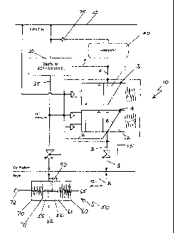
Figures 1 to 6 show a park brake control assembly, indicated generally at 10,
for a rail
vehicle (not shown) having a brake pipe 20, a distributor 30, an air supply
being a
reservoir 40, and a brake cylinder 50, in which are included a service brake
70 and a
park brake 60.
In this embodiment there is a single brake pipe 20 for providing the air
supply for
reservoir 40 and for conveying pneumatic braking signals using a pneumatic
distributor 30. As shown in Figures 1 ¨ 6, the reservoir 40 is fed by the
brake pipe 20,
with a check valve 75 ensuring air flows only in the direction of the
reservoir 40. The
reservoir 40 supplies the air used in service/emergency braking as well as
that used for
controlling the park brake 60. It should be appreciated that the invention is
not limited
to this application, and may apply to two- pipe systems as well as ECP systems
and to
systems where the park brake is supplied with air either from a separate
reservoir or
directly from the brake pipe or a second pipe (if present).
The distributor 30 and the park brake control assembly 10 each has an output
port 35
and 15 respectively.
In this preferred embodiment, the brake cylinder 50 has two chambers 55 & 56.
With no air pressure in chambers 55 and 56, the spring 65 applies force via
park brake
piston 61 and spindle 62 to the top surface of service brake piston 71,
causing force to
be applied to the brake mechanism via pushrod 72 (park brake is applied).
The output 35 of the distributor 30 may supply air to both the
service/emergency brake
chamber 55 and park brake chamber 56 of the brake cylinder 50, but the output
15 of
the park brake control assembly 10 can only supply air to the park brake
chamber 56 of
CA 02876028 2014-12-08
WO 2013/181707 PCT/AU2013/000602
8
the brake cylinder 50. By the use of an anti-compound valve 90, the larger of
the air
pressures from the output of the park brake control assembly 15 and the output
of the
distributor 35 is directed into the park brake chamber 56 of the brake
cylinder 50.
The air pressure in service brake chamber 55 acts on service brake piston 71,
causing
force to be applied to the brake mechanism via pushrod 72 (service brake is
applied).
The air pressure in park brake chamber 56 acts on park brake piston 61 in
opposition to
the force of spring 65, reducing or overcoming the force acting via spindle 62
onto the
top surface of service brake piston 71. If the pressure in chamber 56 is
higher than a
pre-determined pressure (park brake release pressure) then there will be no
force acting
via spindle 62 on piston 71, and the park brake is released.
The park brake control assembly 10 has two spring biased pneumatic valves 11 &
12
which operate to supply air to the park brake chamber 56 of the brake cylinder
50 in
series, and to vent air from the park brake chamber 56 in parallel via venting
ports 13
& 14 on each valve 11 & 12, respectively.
The first spring biased valve 11 is responsive to pressure in brake pipe 20.
The second
spring biased valve 12 is responsive to pressure in the output port 35 of the
distributor
30, as well as to pressure in the output port 15 of the park brake control
assembly 10.
The first and second valves 11 & 12 are bi-state valves which operate in the
following
way: in a first state (open) they each permit air to flow from the reservoir
40 to the
park brake chamber 56 of the brake cylinder 50, and in a second state (closed)
they
each vent air from the park brake chamber 56 of the brake cylinder 50. The two
bi-
state valves 11 & 12 operate together in series in order to supply air from
the reservoir
40 to the park brake chamber 56: they must each be in their first (open) state
at the
same time to achieve this result. They also operate in parallel to vent air
from the park
brake chamber 56 as air is vented if either or both of the valves 11 & 12 are
in their
second (closed) state. Both of these valves are normally in their second
(closed) state
in the absence of any control input signals. Therefore, there is a fail-safe
aspect of the
invention ¨ when the normally closed state the system is vented and the park
brake is
applied.
CA 02876028 2014-12-08
WO 2013/181707 PCT/AU2013/000602
9
Preferably, the valves 11 & 12 in the park brake control assembly 10 are set
to change
state at pre-determined air pressures (in this embodiment, both valves are set
to 200
kilopascals or kPa). It is to be understood that valves 11 and 12 need not
both be set at
the same pressure.
The preferred embodiment of the invention is now described in relation to six
modes
of operation, illustrated in Figures 1 ¨ 6.
i) System charging (Refer to Fig. 1)
Once vehicles are connected to a locomotive (not shown), air is provided along
the
brake pipe 20 to charge the reservoir 40 on each vehicle. A check valve 75
makes sure
that air from the reservoir 40 does not feed back into the brake pipe 20. The
reservoir
40 is available to provide air in service braking, via the distributor 30, as
well in park
brake applications, via the park brake control assembly 10 (lines A). While
the
reservoir 40 is filling, no service brake is applied and no air is available
to release the
park brake 60. In this mode, the park brake control assembly 10 is connected
to
atmosphere via the two valves 11 & 12 and the park brake 60 is applied (lines
B).
ii) System charging, park brake application (Refer principally to Fig. 2)
As pressure in the brake system increases, it starts to fill a timing
reservoir 85 (see Fig
5) through the check valve/choke 80. As air cannot pass through the check
valve 81 in
the opposite direction, the rate of pressure increase in the timing reservoir
85 is
determined by the size of the choke 82 and the volume of the timing reservoir
85, and
so the pressure in the timing reservoir 85 will rise at a slower rate than
pressure in the
brake pipe 20 when the system is charging. When the pressure in the timing
reservoir
85 is higher than 200 kPa (in this embodiment), the first valve 11 of the park
brake
control assembly opens and allows the pressure in the reservoir 40 to reach
the second
valve 12, which remains closed. The wagon is still in charging mode and the
park
brake 60 is still applied.
iii) First service brake application ¨ park brake release (Refer to Fig. 3)
Once the wagons are fully charged, the driver will be ready to apply the
service brake,
allowing the driver to release the park brake 60. Upon initiating the service
brake, by
reducing the pressure in brake pipe 20, the first and second valves 11 & 12 in
the park
CA 02876028 2014-12-08
WO 2013/181707 PCT/AU2013/000602
brake control assembly 10 will release the park brake 60 because the
distributor 30
will, in response to the brake pipe pressure reduction, send an output
pressure to the
service brake chamber 55 within the brake cylinder 50 (lines C). This brake
cylinder
pressure will also be a control signal to the second valve 12 of the park
brake control
5 assembly 10, to allow pressure from the reservoir 40 to reach the park
brake chamber
56. As long as there is a pressure higher than 200 kPa in the reservoir 40,
the same
pressure will keep the valve 12 open and make sure that the park brake 60 is
released
(lines D). In an automatic distributor setup, the brake pipe pressure does not
go below
200 kPa unless an emergency brake request occurs. This means that the first
valve 11
10 of the park brake control assembly 10, responsive to the brake pipe 20,
will remain
open and so will not cause a ventilation of the park brake chamber 56 and have
a park
brake 60 application as a result. The driver can then operate the controls to
recharge
brake pipe 20. This will result in distributor 30 releasing the service brake
application,
and the pressure at output port 35 will reduce to 0 kPa. The pressure acting
on valve 12
from output port 35 will also reduce to 0, however the pressure from the park
brake
control assembly 10 at output port 15 will maintain valve 12 in its open
state, so the
pressure in park brake chamber 56 will not be exhausted and park brake 60 will
remain
in the release state.
Subsequent service brake application and release operations can be made by the
driver
and the park brake 60 will remain in the release state due to valve 12 being
retained in
the open position as described above.
iv) Park brake application (Refer to Fig. 4)
An application of the park brake control assembly 10 is done by ventilating
the brake
pipe 20 to zero (by the driver or wagon break-away). As the brake pipe 20
pressure
reduces, it exhausts the timing reservoir 85 (Fig. 5) through the check
valve/choke 80.
As air can pass freely through the check valve 81 in this direction, the
pressure in the
timing reservoir 85 will fall at a similar rate to the pressure in the brake
pipe 20. This
means that the first valve 11, controlled by the brake pipe/timing reservoir
85 pressure,
will close and ventilate the park brake chamber 56. However, at the same time
the
reduction in brake pipe pressure will cause an emergency brake request from
the
distributor 30, which will send a service (or emergency) brake pressure to the
CA 02876028 2014-12-08
WO 2013/181707 PCT/AU2013/000602
11
service/emergency brake chamber 55 of brake cylinder 50. The brake cylinder 50
will
be equipped with an anti-compound valve 90 not allowing the brake cylinder 50
to
have both service and park brake pressure applied at the same time. The same
pressure
in the service/emergency brake chamber 55 will be sent into the park brake
chamber
56 and compress the park brake spring 65 accordingly. If the wagon is left in
this state,
once the air has been exhausted or has leaked out from the service/emergency
brake
chamber 55 (and the park brake chamber 56), the park brake 60 will apply
completely.
v) Release of emergency brake - continued park brake application (Refer to
Fig.5)
After exhausting the brake pipe 20 to zero, the train driver can now release
the
emergency brake application by recharging the brake pipe 20. As the brake pipe
pressure increases, it starts to fill the timing reservoir 85 through the
check
valve/choke 80. As air cannot pass through the check valve 81 in the opposite
direction, the rate of pressure increase in the timing reservoir 85 is
determined by the
size of the choke 82 and the volume of reservoir 85, and so the pressure in
the timing
reservoir 85 will rise at a slower rate than brake pipe 20 pressure when the
system is
charging. When the pressure in the timing reservoir 85 is higher than 200 kPa,
the first
valve 11 opens and allows pressure from the reservoir 40 to reach the second
valve 12.
By this time, the brake pipe 20 pressure will have risen sufficiently to cause
the
distributor 30 to release the service/emergency brake application, and
service/
emergency brake chamber 55 pressure will have reduced below 200 kPa, allowing
the
second valve 12 to close; therefore air from reservoir 40 cannot reach the
park brake
chamber 56 and the park brake 60 remains applied.
vi) Isolation of park brake control assembly (Refer to Fig. 6)
If an isolation of a park brake 60 is necessary, an isolation cock 100 is
closed to isolate
the park brake chamber 56 from the park brake control assembly 10. The same
isolation cock 100 will ventilate the downstream side of the park brake
chamber 56
and apply the park brake 60 fully. Air may be present between output port 15
and
isolation cock 100, depending on the state of inputs to valves 11 and 12, but
this will
have no effect if isolation valve 100 is closed.
CA 02876028 2015-10-27
12
Once the isolation cock 100 has been applied, manual release of the park brake
needs to
be effected to release the spring force inside the park brake 60, which then
enables an
operator to move the wagon without the spring park brake applied. To reset the
function,
the isolation cock 100 needs to be opened and the park brake chamber 56
charged (by
making a service brake application) to make the park brake 60 ready for park
brake
functionality again.
If a wagon is required to be operated in service with the park brake 60
isolated, then the
service brake will also need to be isolated on that wagon by closing isolation
cock 110, so
that the park brake 60 mechanism is not reset by a service brake application
via the anti-
compound valve 90.
It will be appreciated by a person skilled in the art that the park brake
control assembly of
the invention is designed to keep the park brake of a wagon applied after the
driver
signals a release from emergency braking and then wishes to recharge the brake
pipe.
Thus the train driver is able to charge the brake pipe and each vehicle's
reservoirs while
maintaining the train in a parked condition.
The park brake control assembly can also require a service brake application
to trigger
the park brake release.
INDUSTRIAL APPLICABILITY
The park brake control assembly is industrially applicable in that it allows a
train driver
to keep the park brake of a wagon applied after signalling a release from
emergency
braking, and to charge the brake pipe and each vehicle's reservoirs while
maintaining the
rain cl a parked condition.