Note: Descriptions are shown in the official language in which they were submitted.
CA 02876154 2014-12-09
WO 2013/187886 PCT/US2012/042077
MEDIUM OR HIGH VOLTAGE SWITCH BUSHING
BACKGROUND
[0001] The present specification relates generally to the field of medium or
high voltage
switches. More particularly, the present specification relates to bushings for
medium or
high voltage switches.
[0002] Switches (e.g., capacitor switches, vacuum interrupter based voltage
switches, etc.)
may be used to connect and disconnect electrical equipment from medium or high
voltage
lines. Switches typically include a vacuum interrupter inside of a bushing,
and the
operational and environmental requirements of medium or high voltage switches
typically
require the use of costly materials such as cycloaliphatic epoxy. An
interrupter is typically
installed in a bushing in one of two ways: (1) encapsulating the interrupter
in a flexible
material, such as urethane or silicone, and then encapsulating the flexible
material into a
cycloaliphatic epoxy, or (2) mechanically installing the interrupter in a
cycloaliphatic epoxy
bushing and using polyurethane to bond the interrupter to the bushing. These
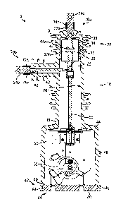
methods
require costly materials and make it prohibitively difficult to salvage or
repair an interrupter
from a damaged bushing.
[0003] Therefore, there is a need for an improved medium or high voltage
switch. There
is also a need for a switch bushing that uses lower cost materials. There is
further a need for
a switch that permits repair and replacement of the interrupter in the
bushing. Yet further,
there is a need for a high or medium voltage switch that uses a low cost
bushing material
and meets environmental requirements of switching applications. There is also
a need for a
method of manufacturing a high or medium voltage switch using a low cost
bushing
material.
SUMMARY
[0004] One embodiment relates to a medium or high voltage switch including a
bottle
assembly and a bushing. The bottle assembly includes a bottle formed of a
first material
and defining a chamber. The bottle assembly further includes a plurality of
contacts for
selectively opening and closing an electrical circuit, the plurality of
contacts disposed within
-1-
CA 02876154 2014-12-09
WO 2013/187886 PCT/US2012/042077
the chamber. The bushing is famied of a second material and defines a cavity
configured to
receive the bottle assembly. The bottle assembly and the bushing have an
interference fit.
[0005] Another embodiment relates to a medium or high voltage switch. The
medium or
high voltage switch includes a first terminal, a bottle assembly, a bushing,
and a
compression member. The bottle assembly includes a bottle defining a chamber
and
includes a plurality of contacts for selectively opening and closing an
electrical circuit, the
plurality of contacts disposed within the chamber. The plurality of contacts
includes a first
contact electrically coupled to the first terminal. The bushing defines a
cavity configured to
receive the bottle assembly, and includes a boss having the first terminal
extending at least
partially therethrough. The compression member compresses the boss against the
terminal
to form a seal.
[0006] Another embodiment relates to a medium or high voltage switch including
a bottle
assembly and a unitary bushing. The bottle assembly includes a bottle defining
a chamber
and includes a plurality of contacts for selectively opening and closing an
electrical circuit,
the plurality of contacts disposed within the chamber. The unitary bushing
defines a cavity
configured to receive the bottle assembly. The bushing includes a head portion
defining the
first cavity and includes a tank portion defining a second cavity receiving an
operating
mechanism interconnected with at least one of the plurality of contacts and
configured to
selectively couple and decouple the at least one of the plurality of contacts
with another of
the plurality of contacts.
[0007] Another embodiment relates to a method of manufacturing a switch. The
method
includes providing a bottle assembly including a bottle defining a chamber and
a plurality of
contacts for selectively opening and closing an electrical circuit, the
plurality of contacts
disposed within the chamber. The method further includes pressing the bottle
assembly into
a bushing, the bottle assembly and the bushing having an interference fit
therebetween.
[0008] Another embodiment relates to a method of manufacturing a switch. The
method
includes providing a bottle assembly including a bottle defining a chamber and
a plurality of
contacts for selectively opening and closing an electrical circuit, wherein
the plurality of
contacts are disposed within the chamber. The method further includes molding
a first
material (e.g., polyurethane) to the bottle assembly, applying dielectric
grease to the first
material, and pressing the bottle assembly into a bushing formed of a second
material, the
bottle assembly and the bushing having an interference fit therebetween.
-2-
[0009] Another embodiment relates to a method of manufacturing a switch. The
method
includes providing a bottle assembly including a bottle defining a chamber and
a plurality of
contacts for selectively opening and closing an electrical circuit, the
plurality of contacts disposed
within the chamber. The method further includes providing a sleeve, applying
dielectric grease to
the bottle, and pressing the bottle into the sleeve, the bottle and sleeve
having an interference fit
therebetween.
[0010] Another embodiment relates to a method of assembling a switch. The
method includes
providing a bushing having a boss disposed thereupon, the bushing defining a
cavity having a
bottle assembly disposed therein, the bottle assembly including a bottle
defining a chamber and a
plurality of contacts for selectively opening and closing an electrical
circuit, the plurality of
contacts disposed within the chamber and comprising a first contact
electrically coupled to a first
terminal, the first terminal extending at least partially through the boss.
The method further
includes disposing a compression member around the boss, and compressing the
compression
member such that the boss forms a seal against the terminal.
10010A1 In a broad aspect, the invention pertains to a medium or high voltage
switch comprising
a first terminal. There is a bottle assembly comprising a bottle defining a
chamber. Means are
provided for a plurality of contacts for selectively opening and closing an
electrical circuit, the
plurality of contacts being disposed within the chamber and comprising a first
contact electrically
coupled to the first terminal. A bushing defines a cavity configured to
receive the bottle
assembly, and comprises a boss having the first terminal extending at least
partially therethrough.
A compression member compresses the boss against the first terminal to form a
seal, the
compression member comprising a sidewall coupled to the boss, and an inwardly
extending
flange coupled to the first terminal.
- 3 --
CA 2876154 2018-10-22
100111 The foregoing is a summary and thus by necessity contains
simplifications,
generalizations, and omissions of detail. Consequently, those skilled in the
art will appreciate
that the summary is illustrative only and is not intended to be in any way
limiting. Other aspects,
inventive features, and advantages of the devices and/or processes described
herein, as defined
solely by the claims, will become apparent in the detailed description set
forth herein and taken in
conjunction with the accompanying drawings.
BRIEF DESCRIPTION OF THE DRAWINGS
[0012] FIG. 1 is a right elevational view schematic drawing of a medium or
high voltage
switch, shown according to an exemplary embodiments.
[0013] FIG. 2 is a left elevational cross-sectional view schematic drawing of
the medium or
high voltage switch of FIG. 1, shown according to an exemplary embodiment.
[0014] FIG. 3 is an enlarged cross-section view schematic drawing of a portion
of the medium
or high voltage switch of FIG. 1, shown in an uncompressed state, according to
an exemplary
embodiment.
- 3a
CA 2876154 2018-10-22
CA 02876154 2014-12-09
WO 2013/187886
PCT/US2012/042077
[0015] FIG. 4 is an enlarged cross-sectional view schematic drawing of a
portion of the
medium or high voltage switch of FIG. 1, shown in a compressed state,
according to an
exemplary embodiment.
[0016] FIG. 5 is an enlarged cross-sectional view schematic drawing of a
portion of the
medium or high voltage switch, shown according to another embodiment.
100171 FIG. 6 is an enlarged cross-sectional view schematic drawing of a
portion of the
medium or high voltage switch, shown according to another embodiment.
[0018] FIG. 7 is an enlarged cross-sectional view schematic drawing of a
portion of the
medium or high voltage switch, shown according to yet another embodiment.
[0019] FIG. 8 is a flowchart of a process for manufacturing a switch,
according to an
exemplary embodiment.
[0020] FIG. 9 is a flowchart of a process for manufacturing a switch,
according to another
embodiment.
[0021] FIG. 10 is a flowchart of a process for manufacturing a switch,
according to
another embodiment.
[0022] FIG. 11 is a flowchart of a process for assembling a switch, according
to yet
another exemplary embodiment.
DETAILED DESCRIPTION
[0023] Referring generally to the FIGURES, a medium or high voltage switch,
and
components thereof, are shown according to an exemplary embodiment. Medium
voltage
switches may be used in utility power distribution environments, for example,
in a pole-
mounted or pad-mounted interrupter, operating in circuits of approximately
1,000 Volts to
38,000 Volts and 200 amps to 400 amps. High voltage switches may be used at
voltage
levels exceeding approximately 38,000 Volts. The switch (e.g., switchgear,
etc.) generally
includes an electrically insulating bushing and a conductor passing
therethrough. The
conductor includes a plurality of selectively separable contacts which allow
the circuit of
which the conductor is a part to be opened or closed. The switch may include
an operating
mechanism configured to selectively close (i.e., join) and open (i.e.,
separate) the pair of
contacts.
[0024] According to an exemplary embodiment, the switch is a vacuum
interrupter based
medium voltage capacitor switch. In such an embodiment, the contacts are
disposed within
an evacuated bottle, and the vacuum inhibits arcing when the contacts are
brought in and
-4-
CA 02876154 2014-12-09
WO 2013/187886 PCT/US2012/042077
out of contact with each other. In such embodiments, the bottle is a vacuum
interrupter.
According to other embodiments, the bottle may be filled with oil, an arc
inhibiting gas
(e.g., sulfur hexafluoride (SF6)), or otherwise contain an arc-inhibiting
medium or
mechanism.
[0025] Before discussing further details of the switch and/or the components
thereof, it
should be noted that references to "front," "rear," "top," "bottom," "inner,"
"outer," "right,"
and "left" in this description are merely used to identify the various
elements as they are
oriented in the FIGURES. These terms are not meant to limit the element which
they
describe, as the various elements may be oriented differently in various
applications.
[0026] It should further be noted that for purposes of this disclosure, the
term "coupled"
means the joining of two members directly or indirectly to one another. Such
joining may
be stationary in nature or moveable in nature and/or such joining may allow
for the flow of
fluids, electricity, electrical signals, or other types of signals or
communication between the
two members. Such joining may be achieved with the two members or the two
members
and any additional intermediate members being integrally formed as a single
unitary body
with one another or with the two members or the two members and any additional
intermediate members being attached to one another. Such joining may be
permanent in
nature or alternatively may be removable or releasable in nature.
[0027] Referring to FIGS. 1 and 2, a medium or high voltage switch 2 is shown
according
to an exemplary embodiment. The switch 2 includes a housing 10 (e.g., bushing,
body, etc.)
having a head 12 (e.g., a head portion) and a tank 14 (e.g., tank portion).
The head 12
includes a first end, shown as top end 16, and a distal second end, shown as
bottom end 18.
A sidewall 20 extending therebetween at least partially defines a first cavity
22.
[0028] The head 12 supports a plurality of terminals 24, shown as a first
terminal 24a and
a second terminal 24b. The first terminal 24a is coupled to a first electrical
contact 26a and
may be coupled to a first side (e.g., positive, negative, ground, load,
electrical equipment,
etc.) of an electrical circuit. The second terminal 24b is coupled to a second
electrical
contact 26b and may be coupled to a second side (e.g., negative, positive,
ground, load,
electrical equipment, etc.) of an electrical circuit. The first and second
electrical contacts
26a, 26b may be selectively coupled and decoupled to close and open the
electrical circuit,
respectively. The particular orientation and number of contacts 26a, 26b is
not shown in a
limiting fashion.
-5-
CA 02876154 2014-12-09
WO 2013/187886 PCT/US2012/042077
[0029] A bottle assembly 28 is supported in the head 12 and includes a bottle
30 (e.g.,
interrupter, body, etc.) and the first and second contacts 26a, 26b. The
bottle 30 defines a
chamber 32 into which the first and second contacts 26a, 26h extend. According
to the
exemplary embodiment shown, the gas (e.g., air) has been evacuated or removed
from the
chamber 32 to substantially form a vacuum. Thus, the creation and propagation
of an
electrical arc as the first and second contacts 26a, 26b are brought into and
out of contact
with one another are inhibited. The bottle 30 may be formed out of any
suitable material,
for example, porcelain or ceramic, and may be embodied in a variety of forms
including
various types of contact mechanisms. The bottle 30 is not shown in a limiting
fashion.
[0030] The head 12 may be formed of any suitable dielectric material, for
example,
cycloaliphatic epoxy, porcelain, polymer, ceramic, etc. According to the
exemplary
embodiment shown, the head 12 is formed of high density polyethylene (HDPE).
HDPE is
approximately twenty percent lighter than cycloaliphatic epoxy, thus
significantly reducing
the weight of the switch, which is a concern, for example, in pole-mount
applications.
Placing the bottle 30 in a dielectric material enables use of the bottle
assembly 28 for
elevated voltages, as well as for outdoor use. The head 12 constitutes at
least a portion of a
bushing, insulating the bottle 30 and electrical conductors between the first
and second
terminals 24a, 24b. The head 12 further protects the bottle 30 and the
electrical conductors
from the external environment (e.g., precipitation, wind, debris, etc.).
[0031] The bottle assembly 28 may further include a sleeve 34 having the
bottle 30
disposed therein. The sleeve 34 may be molded (e.g., overmolded, injection
molded,
poured, etc.) on the bottle 30. According to an exemplary embodiment, the
sleeve 34 is
formed of polyurethane, which may bond to the bottle 30.
[0032] The bottle assembly 28 is disposed within the first cavity 22 of the
head 12.
According to the exemplary embodiment shown, the bottle assembly 28 is an
interference
fit (e.g., press fit, force fit, etc.) with the head 12. To facilitate the
interference fit, an inner
surface 36 of the head 12 may be tapered between the bottom end 18 and the top
end 16,
from a diameter greater than the diameter of the bottle assembly 28 to a
diameter equal to or
less than the diameter of the bottle assembly 28. In an embodiment having a
sleeve 34, the
sleeve 34 may be compressed between the head 12 and the bottle 30. Compressing
the
sleeve 34 between the head 12 and the bottle 30 enables a better fit and
allows the sleeve 34
to absorb the thermal contraction and expansion of the bottle 30 while
maintaining contact
-6-
CA 02876154 2014-12-09
WO 2013/187886 PCT/US2012/042077
with both the head 12 and the bottle 30. A dielectric grease 38 (e.g.,
silicone grease) may
be used between the inner surface 36 of the head 12 and the bottle assembly
28. The
dielectric grease may be applied as a layer, coating, etc., to an outer
surface of the sleeve 34.
The dielectric grease 38 fills voids between the bottle assembly and the head
12, thereby
maintaining electrical integrity of the opposite polarities of the switch 2.
[0033] Providing an interference fit between the head 12 and the bottle
assembly 28
provides a low-cost coupling having electrical integrity. Further, HDPE is
extremely
chemically resistant, and is thus very difficult to chemically bond to unless
the surface is
prepared, for example, using an ion or electron gun. Providing an interference
fit creates a
mechanical joint that does not rely on chemical bonding, and is thus
particularly useful in
the embodiment using a head 12 formed of HDPE.
[0034] According to the exemplary embodiment shown, the mechanical joint
between the
sleeve 34 and the head 12 is reversible with sufficient force. In one
embodiment, the bottle
assembly 28 may be decoupled (e.g., pulled from, pushed from, etc.) from the
head 12 in
order to repair or replace the component, thus lowering production costs and
facilitating
servicing of the switch during production and in the field.
[0035] Referring to FIG. 5, an enlarged view of a portion of switch 2 is
shown, according
to another embodiment. The sleeve 34 may be formed separately from the bottle
30. For
example, the sleeve 34 may be injection molded. The bottle 30 may then be
pressed into the
sleeve 34. According to one embodiment, there is an interference fit between
the sleeve 34
and the bottle 30. A dielectric grease 35 (e.g., silicone grease) may be used
between an
outer surface of the bottle 30 and an inner surface of sleeve 34. The
dielectric grease 35
fills voids between the bottle 30 and the sleeve 34, thereby maintaining
electrical integrity
of the opposite polarities of the switch 2.
[0036] Referring to FIG. 6, an enlarged view of a portion of switch 2 is
shown, according
to another embodiment. A bottle assembly 128 is shown disposed within the
first cavity 22
of the housing 10. According to the exemplary embodiment shown, the bottle
assembly 128
is a loose fit with the housing 10. To facilitate the loose fit, a diameter of
the inner surface
36 of the housing 10 is greater than a diameter of the bottle assembly 128.
For example, a
diameter of a sidewall 131 of the sleeve 134 is less than the diameter of the
inner surface 36,
thereby forming a gap 39 (e.g., chamber, cavity, receptacle, etc.). A
substantially
continuous media of dielectric grease 138 (e.g., layer, coating, pool,
barrier, etc.) is disposed
-7-
CA 02876154 2014-12-09
WO 2013/187886 PCT/US2012/042077
between the sleeve 134 and the housing 10. The dielectric grease 138 fills the
gap 39
between the sleeve 134 and the housing 10, thereby maintaining electrical
integrity of the
opposite polarities of the switch 2. The dielectric grease 138 may be disposed
in the gap 39
after the bottle assembly 128 is placed in the housing 10, for example, using
an injection
process; before the bottle assembly 128 is placed in the housing 10, for
example, pouring
the dielectric grease into the housing 10 and allowing grease to flow along
the sidewall 131
as the bottle assembly 128 displaces the grease in the housing 10; or some
combination
thereof According to one embodiment the gap 39 may be evacuated before the
dielectric
grease is injected into the gap.
[0037] The sleeve 134 is shown to include a flange 137 (e.g., flange, ledge,
lip, etc.)
extending outwardly from a bottom portion (e.g., bottom end, etc.) of the
sleeve 134 or
sidewall 131 thereof, the flange 137 configured to contact the inner surface
36 of the
housing 10 and seal the dielectric grease 138 in the gap 39. According to
another
embodiment, a discreet sealing member (e.g., an o-ring, etc.) may be disposed
between the
sleeve 134 and the housing 10. According to various embodiments, one or both
of the
sleeve 134 and the housing 10 may include a groove configured to receive or
seat the
sealing member.
[0038] Referring to FIG. 7, an enlarged view of a portion of switch 2 is
shown, according
to yet another embodiment. A bottle assembly 228 is shown disposed within the
first cavity
22 of the housing 10. According to the embodiment shown, the sleeve 234 may be
at least
partially spaced apart from the bottle 30, thereby defining a gap 41 (e.g.,
chamber, cavity,
receptacle, etc.). A substantially continuous media of dielectric grease 241
(e.g., layer,
coating, pool, barrier, etc.) is disposed between the sleeve 234 and the
bottle 30. The
dielectric grease 138 fills the gap 41 between the sleeve 234 and the bottle
30, thereby
maintaining electrical integrity of the opposite polarities of the switch 2.
The dielectric
grease 241 may be placed in the gap 41 after the sleeve 234 is placed or
formed around the
bottle 30, for example, using an injection process; before the bottle 30 is
placed in the
sleeve 234, for example, pouring the dielectric grease into the sleeve and
allowing grease to
flow along the sidewall 231 as the bottle 30 displaces the grease in the
sleeve 234; or some
combination thereof. According to one embodiment the gap 41 may be evacuated
before
the dielectric grease is injected into the gap. The sleeve 234 is shown to
define a gap 39
similar to the gap 39 described with respect to FIG. 6. According to another
embodiment,
-8-
CA 02876154 2014-12-09
WO 2013/187886
PCT/US2012/042077
the outer portion of the sidewall 231 may be formed to have an interference
fit between the
sleeve and the housing 10 as shown and described with respect to FIG. 2.
[0039] The sleeve 134 is shown to include a flange 233 (e.g., flange, ledge,
lip, etc.)
extending inwardly from a bottom portion (e.g., bottom end, etc.) of the
sleeve 234 or
sidewall 231 thereof, the flange 233 configured to contact an outer surface of
the bottle 30
and seal the dielectric grease 241 in the gap 41. According to another
embodiment, a
discreet sealing member (e.g., an o-ring, etc.) may be disposed between the
sleeve 234 and
the bottle 30. According to various embodiments, one or both of the sleeve 234
and the
bottle 30 may include a groove configured to receive or seat the sealing
member.
[0040] Returning to FIGS. 1 and 2, the head 12 is further shown to include an
arm 40
supporting the second terminal 24b and extending laterally from the sidewall
20. The
sidewall 20 is shown to extend vertically, and the arm 40 is shown to extend
perpendicularly therefrom; however, it is contemplated that the sidewall 20
and the arm 40
may be placed in other orientations or at other angles relative to each other.
A cable 42
(e.g., terminal cable) extending through the arm 40 at least partially
interconnects the
second terminal 24b and the second contact 26b.
[0041] The tank 14 includes a first end, shown as top end 44, and a second
end, shown as
bottom end 46, and sidewall 48 extending therebetween. As shown, the top end
44 is
proximate the head 12, and the bottom end 46 is distal therefrom. The tank 14
defines a
second cavity 50 configured to receive an operating mechanism 52 (e.g.,
closing
mechanism, opening mechanism, etc.) and defines an opening 54 for the passage
of the
operating mechanism 52 therethrough, for example, during assembly or repair of
the switch
2.
[0042] As shown, the operating mechanism 52 is interconnected with the second
contact
26b via an operating rod 56. The operating mechanism 52 actuates the operating
rod 56 to
selectively couple and decouple the second contact 26b from the first contact
26a.
Operating mechanism 52 may be remotely operated, for example using solenoids,
or
manually operated, for example using a handle 58.
[0043] According to one embodiment, the tank 14 may be formed separately from
the
head 12 and subsequently coupled thereto. According to another embodiment, the
head 12
and the tank 14 are portions of a unitary bushing or housing 10. According to
various
embodiments, the unitary housing 10 may be formed as a single, injection
molded or blow-
-9-
CA 02876154 2014-12-09
WO 2013/187886 PCT/US2012/042077
molded HDPE component. Forming the head 12 and the tank 14 as a unitary
housing 10
reduces production costs. For example, in highly corrosion resistant
applications, the cost
of the stainless steel used for the tank could approach half of the material
cost of the switch.
Also, forming the head 12 and the tank 14 as a unitary housing 10 eliminates a
joint
between the head 12 and the tank 14 that would otherwise require sealing
against leakage.
[0044] According to the embodiment shown, the opening 54 is defined by the
bottom end
46 of the tank 14. According to another embodiment, the opening 54 passes
through the
sidewall 48. Forming the opening 54 in the bottom end 46 of the tank 14
discourages
precipitation or debris from entering the cavity 50. That is, forming the
opening 54 in the
bottom end 46 of the tank 14 would require precipitation or debris to travel
upwards to enter
the housing 10.
[0045] A cover 60 may close or seal the opening 54. For example, the cover 60
may form
an airtight seal with the tank 14. Forming an airtight seal may inhibit humid
or corrosive air
(e.g., salt spray) from entering the switch and reacting with the components
thereof.
According to the embodiment shown, the cover is received in the opening 54,
against a
seating surface 62, wherein the seating surface 62 includes an inner surface
64 of the tank
14 and a ledge 66 formed therein. According to various embodiments, the cover
60 may
seal against one or both of the inner surface 64 and the ledge 66. The cover
60 may be
coupled to the tank 14 by any suitable manner, for example, by press fit, snap
fit, threaded,
adhesive, or, as shown, fasteners 68. According to other embodiments, the
cover 60 may
couple to a bottom or outer surface of the tank 14, or may include a sealing
member (e.g.,
gasket, o-ring, etc.).
[0046] According to other embodiments, the bottom end 46 of the housing 10 may
be
formed to coupled to a baseplate (not shown). In such an embodiment, the
switch 2 may not
include a cover 60, or the baseplate may comprise a cover. According to one
embodiment,
more than one (e.g., two, three, etc.) switches 2 may be coupled to the base
plate. For
example, the housings 10 of each of three switches 2 may be coupled to a
single, flat
baseplate. One or more spacers maybe disposed between the housings 10 and the
baseplate.
[0047] Referring to the exemplary embodiment shown in FIGS. 2-4, the head 12
includes
a first compression assembly 70a, shown proximate the top end 16 of the head
12, and a
second compression assembly 70b, shown proximate a distal end of the arm 40.
The first
-10-
CA 02876154 2014-12-09
WO 2013/187886 PCT/US2012/042077
compression assembly 70a includes a boss 72a having the first terminal 24a
extending
therethrough and a compression member, shown as ring 74a.
[0048] Referring now to FIGS. 3 and 4, an enlarged portion of the switch 2
including the
second compression assembly 70b is shown in an uncompressed state and
compressed state,
respectively, according to an exemplary embodiment. The description and
components of
the second compression assembly 70b provided herein are generally applicable
to the first
compression assembly 70a. The second terminal 24b extends at least partially
through a
second boss 72b, and a compression member, shown as ring 74b, compresses the
second
boss 72b against the second terminal 24b to form a seal. According to an
exemplary
embodiment, the ring 74b is crimped, for example using a crimping tool, to
compress the
ring 74b and, therefore, the boss 72b against the terminal 24b.
[0049] According to the embodiment shown, the ring 74b has a sidcwall 76b and
an
inwardly extending flange 78b. The flange 78b may contact the terminal 24b
when the ring
74b is compressed, thereby keeping the ring 74b at the same electrical
potential as the
terminal 24b. In other embodiments, a conductor (e.g., a wire, a disc, a
gasket, a washer,
etc.) may extend between the terminal 24b and the ring 74b to equalize the
electrical
potential.
[0050] The terminal 24b may include at least one groove 80 configured to
receive a
portion of the boss 72b when the boss 72b is compressed against the terminal
24b. When
the boss 72b is compressed into the groove 80 of the terminal 24b, the
terminal 24b is
mechanically coupled to the head 12. Accordingly, compressing the boss 72b
against the
terminal 24b at least partially retains the bottle assembly 28 in the housing
10. Further, the
coupling of the boss 72b in the grooves 80 may form a substantially airtight
seal between
the head 12 and the terminal 24b. Forming an airtight seal may inhibit humid
or corrosive
air (e.g., salt spray) from entering the switch and reacting with the
components thereof.
[0051] A gasket 82b may be disposed between the ring 74b, the boss 72b, and
the terminal
24b. Depending on the material selection for the gasket 82b, the gasket may
form a
substantially water and/or airtight seal between the terminal 24b and the head
12 and/or may
electrically couple the terminal 24b and the ring 74b.
[0052] According to various embodiments, a compression member may be formed as
a
spring to provide the compressive force around the boss 72b instead or in
conjunction with
the ring 74b. The compression member may include a screw and a pattern in the
ring such
-11-
CA 02876154 2014-12-09
WO 2013/187886 PCT/US2012/042077
that rotating the screw causes the ring to tighten, or the compression member
may be
substantially C-shaped and a screw draws the opposite ends of the member
together.
[0053] According to other embodiments, one or more fasteners (e.g., rivets,
screws, pins,
etc.) may extend through the boss 72b and the terminal 24b to retain or
support the terminal
24b relative to the housing 10. Accordingly, the fastener may retain or
support the bottle
assembly 28 within the head 12. According to other embodiments, the fastener
may also
extend through a retention member. Referring briefly to FIG. 3, according to
one
embodiment, the retention member may have a sidewall and an inwardly extending
flange
similar to the sidewall 76b and flange 78b of the embodiment of the ring 74b
shown. The
retention member may or may not be compressed. In an embodiment where the
retention
member is not compressed, the inwardly extending flange of the retention
member may
extend further inward than is shown in FIG. 3 to contact the terminal 24b. In
an
embodiment where the retention member is compressed, the retention member may
be a
compression member. According to other embodiments, a wire, gasket, or other
conductor
may be used to equalize the potential between the terminal 24b and the
retention member.
The retention member may be loose or press fit onto the boss 72b.
[0054] Referring to FIGS. 8-10, methods of manufacturing and assembling a
switch 2 are
shown and described, according to exemplary embodiments.
[0055] Referring to FIG. 8, a flowchart of a process 100 for manufacturing a
switch is
shown according to an exemplary embodiment. Process 100 is shown to include
the steps
of providing a bottle assembly including a bottle defining a chamber and a
plurality of
contacts for selectively opening and closing an electrical circuit, the
plurality of contacts
disposed within the chamber (step 102), and pressing the bottle assembly into
a bushing, the
bottle assembly and the bushing having an interference fit therebetween (step
104).
[0056] Referring to FIG. 9, a flowchart of a process 110 for manufacturing a
switch is
shown according to another embodiment. Process 110 is shown to include the
steps of
providing a bottle assembly including a bottle defining a chamber and a
plurality of contacts
for selectively opening and closing an electrical circuit, the plurality of
contacts disposed
within the chamber (step 112), molding a first material (e.g., polyurethane)
to the bottle
assembly (step 114), applying dielectric grease to the first material (step
122), and pressing
the bottle assembly into a bushing formed of a second material (e.g., high-
density
polyethylene), the bottle assembly and the bushing having an interference fit
therebetween
-12-
CA 02876154 2014-12-09
WO 2013/187886 PCT/US2012/042077
(step 124). According to one embodiment, the step of molding a first material
(step 114)
may include the steps of disposing the bottle assembly into a mold (step 116),
disposing the
first material into the mold (step 118), and curing the first material (step
120).
[0057] Referring to FIG. 10, a flowchart of a process 150 for manufacturing a
switch is
shown according to another embodiment. Process 150 is shown to include the
steps of
providing a bottle assembly including a bottle defining a chamber and a
plurality of contacts
for selectively opening and closing an electrical circuit, the plurality of
contacts disposed
within the chamber (step 152), providing a sleeve (step 156), applying
dielectric grease to
the bottle (step 158), and pressing the bottle into the sleeve, the bottle and
sleeve having an
interference fit therebetween (step 160). According to one embodiment, the
process 150
may include the step of molding the sleeve from a first material (e.g.,
polyurethane) (step
154).
[0058] Referring to FIG. 11, a flowchart of a process 200 for assembling a
switch is
shown according to another exemplary embodiment. Process 200 is shown to
include the
steps of providing a bushing having a boss disposed thereupon, the bushing
defining a
cavity having a bottle assembly disposed therein, the bottle assembly
including a bottle
defining a chamber and a plurality of contacts for selectively opening and
closing an
electrical circuit, the plurality of contacts disposed within the chamber and
comprising a
first contact electrically coupled to a first terminal, the first terminal
extending at least
partially through the boss (step 202), disposing a compression member around
the boss
(step 204), and compressing (e.g., tightening, crimping, etc.) the compression
member such
that the boss forms a seal against the terminal (step 206). According to
various
embodiments, the seal may be a liquid or airtight seal. According to other
embodiments,
the compressing the compression member compresses the boss against the
terminal at least
partly retains the bottle assembly in the housing.
[0059] The construction and arrangement of the elements of the switch as shown
in the
exemplary embodiments are illustrative only. Although only a few embodiments
of the
present disclosure have been described in detail, those skilled in the art who
review this
disclosure will readily appreciate that many modifications are possible (e.g.,
variations in
sizes, dimensions, structures, shapes and proportions of the various elements,
values of
parameters, mounting arrangements, use of materials, colors, orientations,
etc.) without
materially departing from the novel teachings and advantages of the subject
matter recited.
-13-
CA 02876154 2014-12-09
WO 2013/187886 PCT/US2012/042077
For example, elements shown as integrally formed may be constructed of
multiple parts or
elements. The elements and assemblies may be constructed from any of a wide
variety of
materials that provide sufficient strength or durability, in any of a wide
variety of colors,
textures, and combinations. Additionally, in the subject description, the word
"exemplary"
is used to mean serving as an example, instance or illustration. Any
embodiment or design
described herein as "exemplary" is not necessarily to be construed as
preferred or
advantageous over other embodiments or designs. Rather, use of the word
"exemplary" is
intended to present concepts in a concrete manner. Accordingly, all such
modifications are
intended to be included within the scope of the present disclosure. Other
substitutions,
modifications, changes, and omissions may be made in the design, operating
conditions, and
arrangement of the preferred and other exemplary embodiments without departing
from the
scope of the appended claims.
[0060] The order or sequence of any process or method steps may be varied or
re-
sequenced according to alternative embodiments. Any means-plus-function clause
is
intended to cover the structures described herein as performing the recited
function and not
only structural equivalents but also equivalent structures. Other
substitutions,
modifications, changes, and omissions may be made in the design, operating
configuration,
and arrangement of the preferred and other exemplary embodiments without
departing from
the scope of the appended claims.
-14-.