Note: Descriptions are shown in the official language in which they were submitted.
-1-
GRILL
FIELD
The present invention relates generally to grills and in
particular, to a closeable grilling apparatus.
BACKGROUND
The present invention pertains to a closable grilling
apparatus that comprises a lower part with an annular gas
burner arranged therein, a heat conducting cone that is
held in the lower part above the gas burner such that it is
spaced apart from the wall of the lower part and features a
central bottom opening that is smaller than the inside
diameter of the annular gas burner, as well as a cooking
grate that is held in the lower part above the heat
conducting cone and a hinged or removable cover.
Grilling apparatuses of this type are known from EP
0653197, wherein these grills are commonly referred to, in
particular, as so-called spherical grills and very widely
used. The initially cited grilling apparatuses correspond
to these known spherical grilling apparatuses. As the name
implies, these grilling apparatuses have an approximately
spherical external shape. The lower part has an
approximately hemispherical shape whereas the cover is
indeed curved, but not realized hemispherical.
The concept of a spherical grill is based on the notion
that the heat generated by an annular gas burner, the
inside diameter of which is greater than a central opening
in a conducting cone held in the lower part, results in an
approximately uniform heat distribution. The heat
predominantly flows around the conducting cone and ascends
along the outside of the wall of the conducting cone and
the inside of the wall of the lower part until it reaches
the cover such that the food being grilled is predominantly
subjected to top heat. However, adequate bottom heat that
CA 2876422 2019-12-10
- 2 -
usually suffices for cooking the food being grilled is also
produced because the conducting cone is also heated by the
annular gas burner. Nevertheless, it would be desirable to
selectively supply heat from above or from below similar to
a baking oven in order to respectively generate top heat or
bottom heat.
EP-0688177 A discloses a grilling apparatus that may be
realized in the form of an open or closed grilling
apparatus and features a burner that is centrally arranged
in the lower part, as well as a heat conducting means that
makes it possible to adjust a different heat conduction,
namely either in the form of uniform radiant heat that is
generated by a plate being heated or in the form of a
convective heat distribution that is achieved by raising
parts of this plate, as well as the openings being formed
thereby, such that heat can be conducted upward either more
centrally or more radially depending on the adjustment.
However, other open or closed grilling apparatuses that
allow a certain heat conduction are also known, for
example, from DE 19515080 A or DE 9411524 U. Although these
grilling apparatuses are also provided with annular
burners, they have a completely different design and the
burners used do not consist of gas burners.
As mentioned above, grilling apparatuses with gas burners
of the initially mentioned type have a tendency to
predominantly generate top heat such that the users
accordingly open the cover and occasionally turn the food
to be grilled in order to achieve uniform browning.
However, this results in unnecessary energy losses and the
constant turning of the food to be cooked also leads to
increased soiling of the grilling apparatus.
CA 2876422 2019-12-10
- 3 -
Although EP 0653917 shows diverse variations that result in
more top heat or more bottom heat, neither variation can be
changed while the grilling apparatus is in use.
SUMMARY
The present invention therefore is based on the objective
of designing a grilling apparatus of the initially
mentioned type in such a way that the food to be cooked can
be alternately supplied with increased top heat or
increased bottom heat during the operation of the grilling
apparatus.
In one aspect, there is provided a closable grilling
apparatus comprising: a lower part having an annular gas
burner arranged therein; a heat conducting cone arranged in
the lower part above the annular gas burner having a
central bottom opening smaller than an inside diameter of
the annular gas burner, the heat conducting cone positioned
spaced apart from a wall of the lower part; openings
arranged in the heat conducting cone around a circumference
thereof, each of the openings formed in a crescent shape; a
cooking grate arranged in the lower part above the heat
conducting cone; a removable cover; an adjustment cone
supported by and arranged within the heat conducting cone;
openings arranged in the adjustment cone around a
circumference thereof; and air deflecting caps integrally
formed on an upper edge of the openings in the heat
conducting cone and directed away from a center of the heat
conducting cone, the air deflecting caps configured for
deflecting ascending hot air inward through the heat
conducting cone when the openings are positioned to at
least partially overlap with the openings in the adjustment
cone, wherein the openings arranged in the heat conducting
cone and the openings arranged in adjustment cone are
positioned for adjustably conducting heat from the annular
gas burner through the cones or around an outside surface
of the heat conducting cone, such that food to be grilled
CA 2876422 2019-12-10
- 4 -
lying on the cooking grate is predominantly subjected to
bottom heat by conducting heat through the cones and food
to be grilled lying on the cooking grate is predominantly
subjected to top heat by conducting heat around the outside
surface of the heat conducting cone.
In another aspect, there is provided a closable grilling
apparatus comprising: a lower part having an annular gas
burner arranged therein; a heat conducting cone arranged in
the lower part above the annular gas burner having a
central bottom opening smaller than an inside diameter of
the annular gas burner, the heat conducting cone positioned
spaced apart from a wall of the lower part; openings
arranged in the heat conducting cone around a circumference
thereof; a cooking grate arranged in the lower part above
the heat conducting cone; a removable cover; an adjustment
cone supported by and arranged within the heat conducting
cone; openings arranged in the adjustment cone around a
circumference thereof; air deflecting caps integrally
formed on an upper edge of the openings in the heat
conducting cone and directed away from a center of the heat
conducting cone, the air deflecting caps configured for
deflecting ascending hot air inward through the heat
conducting cone when the openings are positioned to at
least partially overlap with the openings in the adjustment
cone; a collar on an upper edge of the heat conducting
cone, the collar protruding horizontally from the heat
conducting cone; and an interruption in the collar, a
length of the interruption defining an adjustment range for
the adjustment cone, wherein the openings arranged in the
heat conducting cone and the openings arranged in
adjustment cone are positioned for adjustably conducting
heat from the annular gas burner through the cones or
around an outside surface of the heat conducting cone, such
that food to be grilled lying on the cooking grate is
predominantly subjected to bottom heat by conducting heat
through the cones and food to be grilled lying on the
CA 2876422 2019-12-10
- 5 -
cooking grate is predominantly subjected to top heat by
conducting heat around the outside surface of the heat
conducting cone.
The drawings show a preferred exemplary embodiment of the
inventive object. In these drawings:
BRIEF DESCRIPTION OF THE DRAWINGS
Figure 1 shows a side view of a closable grilling
apparatus with open cover that is arranged on a
mobile base and
Figure 2 shows a rear view of the same grilling
apparatus with mobile base, whereas
Figure 3 shows a perspective view of the same grilling
apparatus with base.
Figure 4 shows the grilling apparatus without the mobile
base and without the cover, wherein the lower
part of the grilling apparatus is illustrated
in the form of a diametrical section and the
other parts of the grilling apparatus are
illustrated in the form of a side view.
Figure 5 shows a side view of the heat conducting cone
and
Figure 6 shows a perspective representation thereof.
Likewise,
Figure 7 shows a side view of the adjustment cone and
Figure 8 shows a perspective representation thereof.
CA 2876422 2019-12-10
-5a-
Figure 9 shows a side view of an alternative design of the
heat conducting cone and
Figure 10 shows a top view thereof, whereas
Figure 11 shows a side view of an alternative adjustment
cone for the heat conducting cone according to
Figures 9 and 10 and
Figure 12 shows a top view thereof.
DETAILED DESCRIPTION OF EMBODIMENTS
The actual grilling apparatus is identified by the
reference symbol 1. It consists of a closable grilling
apparatus that comprises a lower part 2 and a cover 8
illustrated in the completely open position. The grilling
apparatus 1 can be completely closed by means of the cover
and is accordingly referred to as a closable grilling
apparatus in this description. In Figures i to 3, the
grilling apparatus 1 is supported on a mobile base. The
mobile base consists of a frame construction 21 with 4
legs and casters 23 that are fixed on said legs and, for
example, may be provided with locking means 24. The mobile
base 20 is covered with a heat-resistant support 25 that
contains a circular receptacle opening, in which the lower
part of the grilling apparatus 1 is supported. The space
remaining underneath the lower part 2 of the grilling
apparatus 1 is relatively large and on its lower end
defined by a bottom 27 and a recessed trough 28, in which
a not-shown gas tank may be arranged. The reference symbol
29 identifies the front cover and a control knob 30 for
adjusting the gas supply to the gas burner protrudes from
said front cover.
Figure 3 shows an oblique perspective view of the grilling
apparatus with the mobile base, as well as the grate 6
CA 2876422 2019-12-10
-5b-
that is not visible in Figures 1 and 2 and was omitted in
Figure 4 in order to provide a better overview.
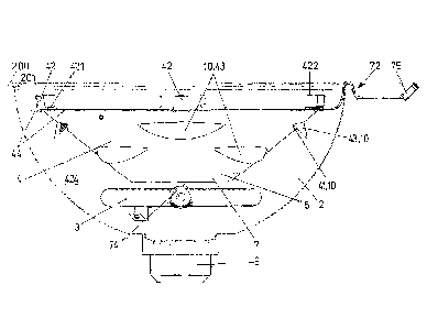
In the grilling apparatus shown in Figure 4, only the lower
part is illustrated in the form of a section and the parts
situated therein are illustrated in the form of a side
view. The lower part 2 has a hemispherical shape and its
upper edge 200 features a bead 201. The heat conducting
cone 4 in the lower part 2 is illustrated in the form of a
side view. An annular gas burner 3 is situated under the
heat conducting cone. The conducting cone 4 features a
lower central opening 5, the diameter of which is smaller
CA 2876422 2019-12-10
= CA 02876422 2014-12-11
- 6 -
than the inside diameter of the annular gas burner 3. The
heat conducting cone 4 situated adjacent to its upper edge
features on the wide opening a horizontal collar 44, to
which approximately u-shaped brackets 42 are attached,
wherein one limb of said brackets extends parallel to the
horizontal collar 44 and is rigidly connected thereto and
an upper limb 422 extends parallel thereto. The upper
parallel limb 422 serves for supporting the grate 6 that is
not illustrated in this figure. The crosspiece 423
connecting the two limbs 421 and 422 is inclined in the
direction parallel to the inner wall 424 of the lower part
4 in the region, in which the aforementioned crosspiece 423
of the bracket 42 contacts the inner wall of the lower
part. This figure furthermore shows the heat conducting
means 10. In principle, these means in the form of openings
41 in the conducting cone are only indicated schematically
in the uppermost lateral regions. In the side view shown,
the openings 41 are covered by air deflecting caps 43. In
Figures 5 and 6, the heat conducting cone 4 is illustrated
separately in the form of a side view (Figure 5) and in the
form of an oblique perspective view from above (Figure 6).
The brackets 42 are not illustrated in this figure.
However, three mounting holes 46 for attaching the brackeL
42, for example, by means of a slot are illustrated in the
horizontal collar 44. Only three brackets 42 are provided
for achieving a secure three-point support. Figure 6
furthermore shows that the horizontal collar 44 has an
interruption 45. This is discussed in greater detail below.
Figure 6 also shows some of the openings 41, wherein the
inside of the air deflecting caps 43 is also visible more
or less clearly in this figure depending on the viewing
angle.
The heat generated by the flames of the gas burner 3
essentially ascends along the outer side of the heat
conducting cone 4. The flow of heated air is now deflected
into the interior of the heat conducting cone 4 through the
CA .02876422 2014-12-11
- 7 -
aforementioned openings 41 by the air deflecting caps 43.
The air deflecting caps 43 may be realized in the form of
crescent-shaped sheet metal parts as shown and merely
welded to the outside along the upper edge 47. In this way,
these air deflecting caps 43 can be realized larger than
the actual openings 41. However, it is also possible to
realize these air deflecting caps 43 in such a way that
only the lower edge of the opening 41 is punched and the
upper edge 47 is formed by a region of the wall 424
produced of the heat conducting cone 4.
The brackets 42 are designed so large that the clearance
between the horizontal collar 44 and the inner wall 424 of
the lower part 2 is bridged and a sufficient gap remains
for conducting the generated heat around the horizontal
collar 44 of the heat conducting cone 4 without creating
relevant heat accumulation.
An adjustment cone 7 rests in the heat conducting cone 4
and is only partially visible in Figure 4. With respect to
its conicality, the adjustment cone 7 is realized identical
to the conducting cone 4. Accordingly, the adjustment cone
7 can be placed into the heat conducting cone 4 such that
its outer side lies on the inner side of the heat
conducting cone 4. The adjustment cone 7 may approximately
have the same structural height as the heat conducting cone
4. However, it is preferably slightly higher such that the
adjustment cone 7 slightly protrudes from the bottom of the
heat conducting cone 4 in the inserted state as illustrated
in Figure 4. However, the adjustment cone could, in
principle, also have a smaller height than the heat
conducting cone. The adjustment cone 7 also features means
for conducting the heat from the gas burner 3 through
the heat conducting cone 4. These means 10 are likewise
realized in the form of openings that are identified by the
reference symbol 71. With respect to their size,
arrangement or position and shape, these openings 71 are
CA 02876422 2014-12-11
- 8 -
realized at least approximately identical to the
corresponding openings 41 in the heat conducting cone. Drip
deflectors 73 are integrally formed on each upper edge of
the openings 71, wherein these drip deflectors are, in
contrast to the heat conducting cone 4, integrally formed
on the inner wall surface in this case. As the name
implies, the drip deflectors 73 serve, in particular, for
deflecting fat dipping onto the wall of the adjustment cone
7 from the food to be grilled on the grate 6 around the
openings 71 such that it is prevented from respectively
dripping onto the inner wall of the lower part between the
heat conducting cone 4 and the outer side of the adjustment
cone 7 in the closed state or through the openings 71 in
the adjustment cone and the more or less congruently
positioned openings 41 in the heat conducting cone in the
open state. In fact, this dripping fat reaches the lower
part 2 through the lower central opening 74 in the
adjustment cone 7 and ultimately drains into a collection
trough 9. The maximum diameter of the central opening 5 in
the heat conducting cone 4 or the central opening 74 in the
adjustment cone 7 is smaller than the inside diameter of
the gas burner 3 such that the dripping fat is reliably
prevented from reaching the gas burner.
A handle bracket 72 is integrally formed on the adjustment
cone 7. This handle bracket extends upward from the
adjustment cone 7 across the clearance between the
adjustment cone and the wall of the lower part 2, namely
approximately along this wall, and then outward over the
edge 200 in the shape of an arc in a practically form-
fitted fashion. On its outer end, a handle 75, preferably
of insulating material, is attached to the handle bracket
72.
The adjustment cone 7 can be turned in the heat conducting
cone 4 by means of the handle bracket 72 that can also be
operated in the closed state of the grilling apparatus 1
CA 02876422 2014-12-11
- 9 -
because it extends between the lower part 2 and the cover
8. Depending on the relative position between the heat
conducting cone and the adjustment cone, the openings 41 in
the heat conducting cone and the openings 71 in the
adjustment cone are positioned more or less congruently on
top of one another. In this case, the adjusting range is
chosen such the openings 41 and 71 do not overlap at all at
one end of the adjusting range and the heat ascending from
the gas burner 3 therefore is entirely conducted around the
heat conducting cone. In this case, the heat ascends in the
region between the heat conducting cone and the inner wall
424 of the lower part 2 and around the horizontal collar 44
such that it reaches the space bordered by the cover 8 and
the food to be grilled lying on the grate 6 is
predominantly exposed to top heat. If a user takes hold of
the handle 75 and displaces the adjustment cone 7 to the
other end of the adjusting range by means of the handle
bracket 72, the openings 41 in the heat conducting cone are
moved into a position, in which they completely overlap the
openings 71 in the adjustment cone such that maximum heat
conduction through the heat conducting cone takes place.
The ascending heat is optimally conducted through the
aforementioned openings by the air deflecting caps 43 and
predominantly ascends in the inner region of the heat
conducting cone and the adjustment cone such that it
directly reaches the underside of the food to be grilled
lying on the grate 6. In this case, the food to be grilled
is predominantly exposed the bottom heat. Any intermediate
positions naturally can be adjusted by means of the handle
bracket 72. Since the handle bracket 72 extends between the
lower part and the cover as already mentioned above, this
adjustment can also be carried out without opening the
cover 7. The adjusting range is defined by the interruption
45 in the horizontal collar 44 of the heat conducting cone
4. When the handle bracket 72 contacts one edge of the
interruption 45, one defined end position is reached
whereas the other above-desc-ribed end position is reached
CA 02876422 2014-12-11
- 10 -
by displacing the handle bracket and therefore the
adjustment cone 7 until the handle bracket contacts the
other edge of the interruption 45. The grate 6 is also
provided with a corresponding recess 61 in order to ensure
that the handle bracket 72 does not get jammed on the
grate.
It should ultimately also be noted that it is possible to
realize the heat conducting cone 4 and the adjustment cone
7 so long that their lower ends can extend through the
annular gas burner 3. This variation is illustrated in
Figures 9-12. Figures 9 and 10 show this alternative
embodiment of the heat conducting cone 4 and Figures 11 and
12 show the corresponding embodiment of the adjustment cone
7. However, this variation is associated with the risk of
heat accumulation. This heat accumulation can be prevented
by either providing slots or the slot-shaped windows shown
as additional heat conducting means 10 in the lowermost
region on the bottom ends of both cones 4, 7. These
additional heat conducting means 10 are arranged in the
lowermost region 11 of the two cones 7 and 10. These means
are realized in the form of rectangular or slot-shaped
window openings. The window openings in the heat conducting
cone 4 are identified by the reference symbol 49 and the
window openings in the adjustment cone are identified by
the reference symbol 79.
The size of the window openings 49, 79 is also chosen such
that the window openings can be adjusted between the
completely closed position, in which the window openings 49
and 79 in the two cones do not overlap one another, and the
completely open position, in which the window openings 49,
79 practically lie congruently on top of one another,
within the potential range of relative rotation between the
two cones. Any intermediate position can also be adjusted.
CA 028764222014-12-11
- 11 -
In contrast to the above-described openings 41 and 71 that
are provided with air deflecting caps 43 and drip
deflectors 73, such air deflecting caps or drip deflectors
are not required on the means 10 in the region 11.
It should furthermore be noted that an annular gas burner
does in this context by no means have to refer to a
circular arrangement. In fact, this term refers to a gas
burner that extends around the central opening 5 of the
heat conducting and/or adjustment cone in an arbitrary
shape.
_
CA 028764222014-12-11
- 12 -
LIST OF REFERENCE SYMBOLS
1 Grilling apparatus
2 Lower part
21 Edge of lower part
3 Gas burner
4 Heat conducting cone
Central opening
6 Grate
7 Adjustment cone
8 Cover
9 Drip trough
Heat conducting means
11 Lowermost region of heat conducting and adjustment
cone
Mobile base
21 Frame construction
22 Legs
23 Casters
24 Locking means
Support
26 Front panel
27 Bottom
28 Recessed trough
29 Front cover
Control knob
200 Upper edge
201 Bead
41 Opening in heat conducting cone
42 Brackets on heat conducting cone
, 43 Air deflecting caps
44 Horizontal collar
_ 45 Interruption
46 Mounting holes
47 Upper edge of opening 41
CA 02876422 2014-12-11
- 13 -
48 Lower edge of opening 41
49 Window opening in heat conducting cone
421 Limb extending parallel to 4
422 Limb
423 Crosspiece
424 Inner wall of lower part
61 Recess on grate
71 Opening in adjustment cone
72 Handle bracket
73 Drip deflector
79 Window opening in adjustment cone