Note: Descriptions are shown in the official language in which they were submitted.
CA 02876503 2014-12-11
WO 2014/008131
PCT/US2013/048626
PIM HOLDER WITH CLAMPING DEVICE
TECHNICAL FIELD
This invention relates generally to holders for patient interface modules
(PIM) and
more particularly, to PIM holders with clamping systems for connecting to
rails.
BACKGROUND
Surgical tables frequently have side rails attached thereto that support
attachments and
accessories commonly required during medical procedures. The side rails
typically extend
along opposing sides of the surgical table. For example, some surgical
procedures require the
use of PIM that may be hung on the rail adjacent the patient.
Attachment of the PIM to the rails is conventionally accomplished using
rigidly, fixed
clamps that use knob screws that require many turns to tighten the clamps onto
the rail in a
fixed and rigid position. Other attachment systems are hooks that hang from
the rails. These
have a tendency to permit the PIM to swing as the bed moves, bumping into
nearby elements
and creating distracting noise. Others are fixed in place on the rail,
requiring special tools to
disconnect the clamps so they can be reoriented in a separate position, and
then to reattached
using the same special tool. They are typically unable to be solid enough to
support the
accessories and still be easily adjusted, moved, or reoriented in convenient
positions.
What is needed is a PIM holder that can be efficiently, yet securely clamped
onto a rail, such
as a surgical table rail. The present disclosure addresses one or more of the
deficiencies in
the prior art.
SUMMARY
In one exemplary aspect the present disclosure is directed to a PIM holder for
attaching a PIM device having a cable to a rail in a medical environment. The
PIM holder
includes a holster and a clamping device. The holster includes an open end
sized to receive a
PIM device and having a cable opening extending from the open end on a side
adjacent the
open end to a side opposite the open end. The clamping device is sized and
configured to
attach the holster to a rail. The clamping device includes a stationary jaw
secured to the
holster and a moving jaw disposed adjacent the stationary jaw. The stationary
jaw and
moving jaw form an opening that receives the rail in a lateral direction and
forms a passage
1
CA 02876503 2014-12-11
WO 2014/008131
PCT/US2013/048626
therebetween to capture the rail. An actuator is pivotable between an open
position and a
closed position to displace the moving jaw to open and close the clamping
device.
In one aspect, the clamping device comprises a biasing system slidably
associated with the
stationary jaw and connected to the moving jaw in a manner that biases the
moving jaw
toward the stationary jaw.
In one aspect, the PIM holder further includes a rotation system disposed
between the
holster and the clamping device. The rotation system includes a first
rotational element
connected to the holster and a second rotational element connected to the
clamping device,
the first rotational element being rotatable relative to the second rotational
element.
In another exemplary aspect the present disclosure is directed to a PIM holder
for attaching a
PIM device having a cable to a rail in a medical environment. The PIM holder
includes a
clamping deice sized and configured to attach to a rail, the clamping device
including a clamp
member having a first jaw and a second jaw, a cam member associated with the
second jaw
and configured to clamp a rail against the first jaw, and a hanger pivotably
connected to
clamp member, the hanger having a connecting portion formed therein. The PIM
holder also
includes a holster pivotably attached to the connecting portion of the hanger
and configured
to pivot in a roll direction substantially perpendicular to the pitch
direction. The holster
includes an open end sized to receive a PIM device and has a cable opening
extending from
the open end on a side adjacent the open end to a side opposite the open end,
the holster
interfacing with the hanger.
In another exemplary aspect the present disclosure is directed to a method of
clamping a PIM holder for a PIM device having a cable to a rail in a medical
environment.
The method includes pivoting an actuator to open a clamping device by linearly
displacing a
moving jaw away from a stationary jaw to place the clamping device in an open
condition,
and introducing a rail between the stationary jaw and the moving jaw in a
lateral direction so
that a holster carried by the clamping device hangs from the rail. The holster
may have an
open end sized to receive a PIM device and may have a cable opening extending
from the
open end on a side adjacent the open end to a side opposite the open end. The
method also
includes releasing the actuator so that a biasing system linearly displaces
the moving jaw
toward the stationary jaw to capture the rail between the stationary and
moving jaws.
2
CA 02876503 2014-12-11
WO 2014/008131
PCT/US2013/048626
BRIEF DESCRIPTION OF THE DRAWINGS
The present disclosure is best understood from the following detailed
description
when read with the accompanying figures. It is emphasized that, in accordance
with the
standard practice in the industry, various features are not drawn to scale. In
fact, the
dimensions of the various features may be arbitrarily increased or reduced for
clarity of
discussion.
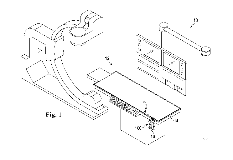
Fig. 1 is an illustration of an exemplary catheter lab system.
Fig. 2 is an illustration of an exemplary PIM holder according to an exemplary
aspect
of the present disclosure with a rail.
Fig. 3 is an illustration of an exemplary PIM holder according to the
exemplary aspect
of Fig. 2 without the rail.
Fig. 4 is an illustration of an exploded view of the exemplary PIM holder
according to
the exemplary aspect of Fig. 2.
Fig. 5 is an illustration of another view of the exemplary PIM holder
according to the
exemplary aspect of Fig. 2.
Fig. 6 is an illustration of an exemplary PIM holder according to an exemplary
aspect
of the present disclosure.
Fig. 7 is an illustration of another view of the exemplary PIM holder
according to the
exemplary aspect of Fig. 6.
Fig. 8 is an illustration of an exemplary clamping device in an exploded view
usable
with a PIM holder according to an aspect of the present disclosure.
Fig. 9 is another illustration of an exploded view of the exemplary clamping
device of
Fig. 8 usable with a PIM holder according to an aspect of the present
disclosure.
Fig. 10 is an illustration of the exemplary clamping device of Fig. 8 usable
with a PIM
holder according to an aspect of the present disclosure.
Fig. 11 is an illustration of an exemplary PIM holder according to an
exemplary
aspect of the present disclosure.
Fig. 12 is an illustration of an exploded view of the exemplary PIM holder
according
to the exemplary aspect of Fig. 11.
Fig. 13 is an illustration of an exploded view of the exemplary PIM holder
according
to the exemplary aspect of Fig. 11.
3
CA 02876503 2014-12-11
WO 2014/008131
PCT/US2013/048626
Fig. 14 is an illustration of an exemplary PIM holder according to an
exemplary
aspect of the present disclosure.
Fig. 15 is an illustration of an exploded view of the exemplary PIM holder
according
to the exemplary aspect of Fig. 14.
Fig. 16 is an illustration of an exploded view of the exemplary PIM holder
according
to the exemplary aspect of Fig. 14.
Fig. 17 is an illustration of an exemplary PIM holder according to an
exemplary
aspect of the present disclosure.
Fig. 18 is an illustration of an exploded view of the exemplary PIM holder
according
to the exemplary aspect of Fig. 17.
Fig. 19 is an illustration of an exploded view of the exemplary PIM holder
according
to the exemplary aspect of Fig. 17.
DETAILED DESCRIPTION
It is to be understood that the following disclosure provides many different
embodiments, or examples, for implementing different features of various
embodiments.
Specific examples of components and arrangements are described below to
simplify the
present disclosure. These are, of course, merely examples and are not intended
to be limiting.
In addition, the present disclosure may repeat reference numerals and/or
letters in the various
examples. This repetition is for the purpose of simplicity and clarity and
does not in itself
dictate a relationship between the various embodiments and/or configurations
discussed.
Moreover, the formation of a first feature over or on a second feature in the
description that
follows may include embodiments in which the first and second features are
formed in direct
contact, and may also include embodiments in which additional features may be
formed
interposing the first and second features, such that the first and second
features may not be in
direct contact. Furthermore, the following paragraphs describe many different
embodiments
of PIM holders with clamping devices. For the sake of ease of understanding,
descriptions
set forth with respect to one embodiment are understood to apply to other
embodiments.
The present disclosure is directed to a PIM holder with a clamping system for
a
patient table that may be easily adjusted or moved to an orientation desired
by a surgeon. It
may be adjusted using only one hand, and does not require special tools. It
can be adjusted
more quickly than conventional knob-screw devices, and still provides a strong
stabilizing
foundation for holding surgical accessories. During procedures, the PIM
holders may be
4
CA 02876503 2014-12-11
WO 2014/008131
PCT/US2013/048626
easily readjusted to another location on the table. Because of its easily
adjustable
characteristics, the PIM holders disclosed herein may make surgical processes
easier to
accomplish, without requiring the surgeon to work around the PIM holders, but
making it so
that the surgeon can easily adjust them, thereby providing easier access to
the patient, more
convenient relocation of the PIM holders, speeding the process of accessory
reorientation,
and possibly contributing to a better patient outcome.
Fig. 1 shows an embodiment of a catheter lab system 10 including a patient
table 12
having a side rail 14 disposed thereon. The catheter lab may also include a
patient interface
module (PIM) 16 adapted to hold a catheter having an imaging probe located
near a distal
end, a control panel, a monitor for displaying images and patient data, and a
processing unit.
Attached to the side rail 14, the operating system may include a PIM holder
100 that receives
and holds the PIM in a location convenient for the medical staff using the
catheter lab system
10.
The rails in this example are rectangular shaped in cross-section, however
rails of
other shapes are contemplated. For example, some rails are cylindrical or
square shaped.
Some IV poles are used as rails. Rails may be of any size, and in one example,
the rails are
with a height of about 1 inches and a width in the range of about 3/8 inch,
although other
sized rails are contemplated.
Figs. 2-6 show the PIM holder 100 in greater detail. The PIM holder 100
comprises a
holster 102 and a clamping device 104 that is attachable to the rail 14 as
shown in Fig. 2.
With reference to Fig. 5, the holster 102 is a rigid device having a receiving
end 106 with a
receiving opening 107 sized to receive a PIM, sides or supports 108 configured
to capture and
retain the PIM therein, and a cable end 110 having a cable opening 112 sized
to permit
passage of a PIM cable (not shown). The cable opening is arranged to extend
from the
receiving opening 107 through the bottom of the holster 102. In this way, a
PIM with a cable
extending from its bottom can be held above the holster so that the cable
laterally enters
through the cable opening 112, and then the PIM may be lowered into and seated
in the
holster 102. In this embodiment, the holster 102 includes inwardly extending
bottom tabs
113 that define the cable opening 112 and prevent through-passage of a PIM
that is disposed
in the holster 102. The holster in Fig. 5 is formed of a sheet metal bent to
create the holster.
However, other embodiments are molded or formed via other manufacturing
techniques. In
this example, the holster includes a rigid hanger tab 114 disposed adjacent
the opening and
configured to carry the clamping device 104.
5
CA 02876503 2014-12-11
WO 2014/008131
PCT/US2013/048626
The PIM holder may be sized, in one example, to receive a PIM. PIM are
frequently
sized with a width in the range of 1.5-3 inches, and a thickness of about .4-3
inches, and a
height in the range of about 3-7 inches. Accordingly some embodiments of the
PIM holsters
have a receiving opening between 3 and 5 inches wide and with a thickness of
between 1.5-3
inches. The cable opening may have a width in the range of about .25 inch or
greater. Other
sizes are contemplated.
The clamping device 104 receives and clamps onto the rail 14 that may be a
rail on
the patient table of the catheter lab system 10 discussed above. Fig. 2 shows
the PIM holder
100 with the clamping device 104 connected to the rail 14, Fig. 3 shows the
PIM holder 100
without the rail 104, Fig. 4 shows the clamping device in an exploded
condition. Fig. 5,
mentioned above, shows a front view of the holder 102 of the PIM holder 100.
Referring to Fig. 3, the clamping device 104 includes a stationary jaw 120, a
moving jaw 122,
a biasing system 124, and an actuator 126. As will be explained below, the
stationary jaw
120 and the moving jaw 122 together form an opening 128 that is sized and
configured to
receive and capture a rail, such as the rail 14. In the embodiments shown, the
stationary jaw
120 is fixed in place relative to the holster 102 by attachment elements,
shown as fasteners or
screws 130. These extend through the holster 102 into receiving holes in the
stationary jaw
120.
The stationary jaw 120 includes a back structure 132 forming the backside of
the
opening 128 and an extending portion 134 forming a top portion of the
stationary jaw 120.
The top portion 134 includes a lip 136 that in cooperation with the top
portion 134 and back
structure 132, forms a laterally extending seat 138 that receives and secures
the rail 14 in
place. A biasing slot 140 extends into the top portion of the back structure
132 of the
stationary jaw 120 and is shaped to receive the biasing system 124. Pivot
holes 142 are
formed in sides of the stationary jaw.
The biasing slot 140 is a partial through hole. It has a first width, shown in
Fig. 4
configured to receive the biasing system 124. However, within the back
structure 132 of the
stationary jaw, the biasing slot 140 has a step, similar to that of a counter
bore. The central
portion of the slot 140 therefore continues through, while there is a shoulder
or step on each
side of the through hole within the slot 140.
The moving jaw 122 includes base plate 146 and a lip 148. The base plate 146
includes a surface that abuts against the bottom of the stationary jaw 120. As
such, the back
structure 132 of the stationary jaw, the base plate 146, and the lip 148
together form a seat
6
CA 02876503 2014-12-11
WO 2014/008131
PCT/US2013/048626
150 that receives and captures the rail 14. The base plate 146 includes a
connecting system
152 that attaches the moving jaw 122 to the biasing system 124. The connecting
system 152
includes through holes 154 and fasteners 156, shown in this embodiment as a
set of fastening
screws.
The biasing system 124 is configured to fit within the biasing slot 140 of the
stationary jaw 120 and includes a bracket 160 and biasing elements 162. In the
embodiments
shown, the bracket 160 is a T-shaped structure having a body 164 and extending
arms 166.
The body 164 is configured to extend into the biasing slot 140 and through the
through hole
of the biasing slot 140. A bottom portion of the body 164 abuts the base plate
146 of the
moving jaw 122. The fasteners 156 connect the base plate 146 to the body 164
of the biasing
system 124.
The biasing elements 162 are disposed between the arms 166 and the shoulders
or
steps within the biasing slot 140. These biasing elements are shown in Fig. 4
as coils springs,
although other biasing elements may be used. The biasing elements 162 bias the
bracket 160
in the direction out of the biasing slot 140, away from the moving jaw 122.
Since the moving
jaw 122 is connected to the bracket 160, so doing also biases the moving jaw
122 toward the
stationary jaw 120. Therefore, the clamping device 104 is biased to a closed
or clamped
position. This reduces the likelihood of inadvertent removal of the rail 14
from the clamping
device 104. A displacement passage (formed through the moving jaw 122 in Fig.
4 behind
the slot 176) extends laterally through the moving jaw 122. As discussed
below, the
displacement passage is used to displace the moving jaw 122 relative to the
stationary jaw
120.
The actuator 126 includes a handle 170 and a plurality of lever arms 172. In
the
embodiment shown, the handle 170 and the lever arms 172 are formed from a
single piece of
sheet metal. In other embodiments, the handle and lever arms are connected to
each other via
welding, and adhesive or other attachment method, or they may be machines from
a single
component, may be molded together, or otherwise formed of a single monolithic
piece. The
handle 170 is configured to be actuated by a health care provider to open the
clamping device
102 in order to attach or remove the PIM holder 100 from the rail 14.
The lever arms 170 include a pivot hole 174 and a sliding slot 176. The pivot
hole
174 aligns with the pivot holes 142 in the stationary jaw 120. A pivot pin
180a, shown here
as a clevis pin, extends through the pivot holes 142 and 174 and acts as an
axle to define a
pivot axis and allows the actuator 126 to pivot about the pin 180a relative to
the stationary
7
CA 02876503 2014-12-11
WO 2014/008131
PCT/US2013/048626
jaw 120. The sliding slot 176 aligns with the displacement passage on the
moving jaw 122.
A displacement pin 180b shown as a clevis pin extends through the sliding slot
176 and
through the displacement passage, connecting the moving jaw 122 to the lever
arms 170.
Washers 182 connect to ends of the clevis pins 180 and prevent removal from
the jaws 120,
122. The actuator 126 may be configured so that the handle 170 extends at an
oblique angle
from the clamping device 104 and the holster 102. This enable easy, one hand
clamping and
release to a rail 14. Although Fig. 4 shows the lever arms 172 disposed within
the stationary
jaw 120, other embodiments have the lever arms 172 disposed on the outside of
the stationary
jaw 120.
In the example shown in Figs. 2-6, the back structure 132 includes spot faces
186
configured to receive compressible bumpers 188. These compressible bumpers 188
may be
formed of a foam, elastomeric, or other compressible material and may permit
snug and
secure clamping of rails of different sizes. While shown on the back structure
132, other
embodiments, include the compressible bumpers at other location on the
clamping device,
including in the seats 138, 150.
In use, a health care provider may use a single hand to attach or detach the
PIM holder
100 to a rail, such as the bed rail 14. A health care provide may press the
handle 170 so that
it pivots about the clevis pin 180a. As it does so, the pivoting lever arm 172
forces the clevis
pin 180b and the moving jaw 122 downward. As the rotation occurs, the clevis
pin 180b
slides along the sliding slot 176. Since the bracket 160 is fixed to the
moving jaw 122, the
bracket 160 moves downward, against the biasing force of the biasing elements
162. This
opens the clamping device 104 enabling it to be placed on a rail, such as a
bed rail or other
structure. When the rail enters the opening 128, it may abut the compressible
bumpers 188.
Depending on the size, it may compress the bumpers. The rail may be seated in
one of the
seats 138, 150. To attach the PIM holder 100 to the rail, the health care
provider needs only
to release the handle 170. The biasing elements 162 then bias the bracket 160
upward, which
carries the moving jaw 122 toward the stationary jaw 120 until the rail is
seated in both the
seats 138, 150 or until the moving jaw 122 comes into contact with the
stationary jaw 120,
thereby capturing the rail within the clamping device 100.
If during the medical procedure, it becomes desirable to move the PIM holder
100, the
holder 100 can be simply opened with one hand and slid along the rail or may
be removed
from the rail and reattached in a different location. Although the actuator
126 pivots relative
8
CA 02876503 2014-12-11
WO 2014/008131
PCT/US2013/048626
to the stationary and the moving jaws 120, 122, the jaws linearly translate
relative to each
other, and do not pivot relative to each other.
Figs. 6 and 7 show an alternative PIM holder 200. The PIM holder 200 includes
a
holster 202 and the clamping device 104. The holster 202 includes a receiving
end 206 with
a receiving opening 207 sized to receive a PIM, sides or supports 208
configured to capture
and retain the PIM therein, and a cable end 210 having a cable opening 212
sized to permit
passage of a PIM cable (not shown). In this embodiment, the holster 202 also
includes a stop
element 214 disposed in a manner to limit how far the PIM may be inserted into
the holster.
A tab 216 adjacent the receiving end 206 has a through hole 218 to permit
hanging from an
IV pole or other equipment commonly found in medical treatment rooms. Its
worth noting
that any of the holsters disclosed herein may include such a tab and system
for hanging as an
alternative to clamping onto a rail. Here, the cable opening 212 also includes
a cable support
220 that includes two spaced, and opposing hooks 222 that cooperate to secure
the PIM cable
in place.
In this embodiment, the holster 202 is aligned with the clamping device so
that the
receiving end 206 of the holster 202 is aligned on its side, or parallel to
the direction of a rail
when the PIM holder 200 is disposed on a rail.
Figs. 8-10 show an additional embodiment of a clamping device, referenced
herein by
the numeral 300. The clamping device 300 may be connected to any PIM holster
described
herein. The clamping device 300 differs from the clamping device 104 because
it is arranged
to connect to either a rectangular rail as described above or a cylindrical
rail, such as, for
example, an IV pole. The general operation of the clamping device 300 is
similar to that
described above, and it will not all be repeated here. The clamping device 300
does have a
different form that enables it to secure to a cylindrical rod. For example the
clamping device
300 includes a stationary jaw 302 and a moving jaw 304. Here the stationary
jaw 302 and the
moving jaw 304 each include angled surfaces 306 that form a seat for the
cylindrical rails.
For example, they each include a lip 308 that is chamfered and includes an
angled
engagement surfaces. Because of the angled engagement surface the overall
structure of the
moving jaw is modified as can be seen in the back view shown in Fig. 9. Here,
the moving
jaw 304 includes a base plate 312 that extends from a body structure designed
to support the
engagement surface of the moving jaw 304. High friction elements 316, such as
elastomeric
elements, may form the interfacing surfaces of the jaws and may be configured
to engage a
rail captured in the jaws.
9
CA 02876503 2014-12-11
WO 2014/008131
PCT/US2013/048626
Figs. 11-13 show an alternative PIM holder 400. The PIM holder 400 includes a
holster 402, the clamping device 104, and a rotation mechanism 404. As will
become
apparent below, the rotation mechanism permits rotation of the holster 402 so
that the PIM
can be hung on a rail in any desired orientation.
The holster 402 includes a receiving end 406 with a receiving opening 407
sized to
receive a PIM, sides or supports 408 configured to capture and retain the PIM
therein, and a
cable end 410 having a cable opening 412 sized to permit passage of a PIM
cable (not
shown). In this embodiment, the cable opening is defined between two holster
bottom
portions 414, and the cable opening forms a part of the overall opening
connection the
receiving end and the cable opening. This embodiment includes a locking tab
420 flexibly
forming a part of the holster 402. The locking tab 420 includes an elastically
deformable
finger 422 and a stop piece 424. The locking tab 420 is sized and positioned
to prevent the
PIM from falling from the holster 402 even if the holster 402 is rotated to
its side or upside
down. In this example, the finger 422 of the locking tab 420 may elastically
deflect to permit
the PIM to be inserted into the opening, and the tab 420 may then elastically
return to its
original position. In this position, the stop piece 424 may extend over the
PIM and
mechanically prevent the PIM from inadvertent removal from the holster.
The rotation mechanism 404 comprises a housing 430, a rotating plate 432, and
a
retention ring 434. The housing 430 is configured to connect directly to the
clamping device
104 via fasteners 436. It includes four spaced fastening holes 438 that
receive the fasteners
436, and the fasteners extend into corresponding holes in the stationary jaw
120 of the
clamping device 104. In addition, the housing includes a central boss 439 and
a two detent
holes 440 extending therethrough. Detent pins 442 pass through the detent
holes 440, and in
this embodiment, extend into pin holes 444 formed in the stationary jaw 120.
The detent pins
442 have rounded tips that interface with the rotating plate 432.
The rotating plate 432 includes a central hole 450 that receives the boss 438
and
maintains the rotating plate in a central position relative to the housing
430. The rotating
plate 432 includes four fastener holes 452 that receive fasteners 454 that
connect the rotating
plate 432 to the holster 402. Four detent holes 456 are disposed in the plate
in a position that
allows them to align with the detent pins 442. The holes 456 may be through
holes, or may
be dimples that receive the detent pins 442. In this embodiment, the detent
holes 456 are
spaced 90 degrees apart. However, other spacing arrangements are contemplated.
CA 02876503 2014-12-11
WO 2014/008131
PCT/US2013/048626
The retention ring 434 includes four fastener holes that receive fasteners 460
that
connect the retention ring 434 to the housing 430. The retention ring 434
secures the rotating
plate 432 within the housing 430 and prevents its removal.
In use, either before or after clamping the clamping device 104 to a rail, the
rotation
mechanism 404 permits a health care provider to rotate the holster 402
relative to the
clamping device 104. By rotating the holster 402, the rotating plate 432 moves
within the
housing 430, which is fixed in place relative to the clamping device 104. As
the rotating
plate 432 rotates, the detent pins 442 engage and disengage the detent holes
456 on the
rotating plate. Accordingly, the user is provided with tactical feedback
indicating when the
holster is rotated each 90 degrees. Furthermore, the detents provide increased
friction to
reduce inadvertent rotation of the holster 402 relative to the clamping device
104.
While two detents are shown, other embodiments include only one or more than
two.
Other embodiments include other detent systems. Some embodiments are
configured to
create an audible click when the detent is aligned with the detent pin. Other
rotational
systems are also contemplated.
Figs. 14-16 show another embodiment of a PIM holder 500. The holder includes a
holster 502 and a clamping portion 504. In this embodiment, the clamping
portion 504
comprises a more integrated rotational and clamping system. The holster 502
includes a
receiving end 506 with a receiving opening 507 sized to receive a PIM, sides
or supports 508
configured to capture and retain the PIM therein, and a cable end 510 having a
cable opening
512 sized to permit passage of a PIM cable (not shown). A holder bottom 514
prevents the
PIM from coming out the bottom.
The clamping device 502 includes a rotation mechanism 520 and a clamping
device
522. The rotation mechanism 520 includes a housing 530, a rotating plate 532,
and a
retention ring 534. The rotation mechanism 520 is similar in many ways to the
rotation
mechanism 404 and the descriptions will not repeated in great detail. In this
embodiment
however, a fastener 536 secures the rotation plate 532 to the housing 530. The
fastener 536
extends through the rotating plate 532 and into the boss 534 on the housing
530.
In this embodiment, the housing 530 is formed to receive a portion of the
clamping
device 522. The clamping device 522 includes a stationary jaw 550, a moving
jaw 552, a
biasing system 554, and an actuator 556. In this embodiment, the stationary
jaw 550 is
formed of a single sheet metal plate and is configured with a body 560 and
with a back
structure 562 and an extending portion 564 with a lip 566. Together these form
a seat in the
11
CA 02876503 2014-12-11
WO 2014/008131
PCT/US2013/048626
stationary jaw for the rail 14. The stationary jaw 550 also includes a tab 568
interfacing with
the biasing system 554 and pivot tabs 570 in tabs used to pivotably connect
the stationary jaw
550 to the actuator 556. The back structure 562 fits into a recess 572 in the
housing 530 that
is non-circular, and therefore, the stationary jaw 550 cannot rotate relative
to the housing.
The stationary jaw 550 is secured to the housing 530 via fastening elements
576 shown as
screws.
The moving jaw 552 is also formed of a single sheet-metal piece and fits
within a
recess 578 the housing 530. It includes a base plate 580, bent to form a lip
and that includes a
connection portion 582 for connecting to the biasing system 554. Tabs 584 with
holes are
used to receive a pin 586 that connect the lower jaw 552 to the actuator 556.
The actuator 556 includes a handle 588 and a lever arm 590. The lever arm 590
includes pivot holes 591 and sliding slots 592. When assembled, the pivot
holes 591 align
with the pivot holes in the stationary jaw 550 and a pivot pin 586 extends
therethrough. The
sliding slots 592 align with holes in the moving jaw 552 that are connected by
a pin.
The biasing system 554 in the embodiment includes attachment elements as
screws
593 and biasing elements 594. The screws 593 extend through the biasing tab
568 on the
stationary jaw 550 and into the moving jaw 552. Each screw 593 is associated
with a biasing
element 594 that biases the screw 593 away from the moving jaw 552, thereby
pulling the
moving jaw 552 toward the stationary jaw 550 in a manner that closes the
clamping device.
Here, the housing 530 has a recess sized to receive the biasing system. Spot
faces 186 are
configured to receive compressible bumpers 188. The overall operation of the
rotation
mechanism 520 and the clamping device 522 is similar to that described above
and will not
be repeated.
Figs. 17-19 show an additional embodiment of a PIM holder 600. This embodiment
includes a holster 602 and a clamping device 604. The holster 602 comprises a
receiving end
606 with a receiving opening 607 sized to receive a PIM, sides or supports 608
configured to
capture and retain the PIM therein, and a cable end 610 having a cable opening
612 sized to
permit passage of a PIM cable (not shown). In this embodiment, the holster 602
includes
inwardly extending tabs 613 disposed along the sides 608 that define the cable
opening 612
and prevent through-passage of a PIM that is disposed in the holster 602.
The holster 602 includes a connector 614 configured to pivotably attach to the
clamping device 604. In the example shown, the connector 614 is formed of a
cylindrical
passageway 616 that permits the holster to pivotably connect to the clamping
device 604.
12
CA 02876503 2014-12-11
WO 2014/008131
PCT/US2013/048626
The connector 614 is also disposed to be offset from a plane through the
backwall of the
holster. This offset allows the holster to pivot within a limited pivot range
while cooperating
with the clamping device 604 to prevent pivoting beyond the vertical range in
one direction.
In this example, where the holster is formed of a piece of sheet metal, the
connector 614 is
formed of metal rolled in a direction away from the side of the holster that
receives the PIM.
The clamping device 604 receives and clamps onto the rail 14 that may be a bed
rail
for the catheter lab system 10 discussed above. The clamping device 604
includes a clamp
body 620, a cam member 622, a hanger 624, and a cushion 626.
The clamp body 620 is a C-shaped member having a laterally extending passage
630
with an opening 632 to the passage 630 that receives the rail. The top of the
passage 630
includes a laterally extending recess 634 formed along the length of the top
passage that
receives the rail, creating a lip that prevents inadvertent removal of the
rail. The bottom of
the passage 630 is formed as a flat surface extending from the opening into
the passage 630
and has a through hole 636 therethrough, which receives the cam member 622. A
lateral
passage 638 along the outside of the clamp body intersects with the through
hole 636 and is
sized to receive a portion of the cam member 622.
The cushion 626 is disposed in the recess 634 in a position to engage a rail
being
inserted into the recess, behind the lip. The cushion 626 may be an
elastomeric or foam
bumper configured as a compressible surface against which the rail may be
pressed. In this
embodiment, it is a cylindrical-shaped bumper. In other embodiments, the
cushion is shaped
in other configurations. In addition to providing a cushion against which the
rail may be
pressed, the cushion also may provide a higher frictional resistance to
lateral sliding,
providing a more reliable holding force on the rail.
The cam member 622 comprises a cam 640 and a handle 642. The cam 640 is
disposed in the through hole 636 and pivotably secured in place by a pivot pin
644 extending
into the clamp body 620 and through the cam 640. Rotation of the cam 640
within the
through hole 636 about the pivot pin 644 increases and decreases the distance
between the
cam 640 and the opposing recess 634 of the clamp body 620 in a manner that
captures a rail
within the clamping device 602. The cam 640 also includes a projecting side
wall 646
disposed along the outer-facing side of the cam 640. The projecting side wall
646 is disposed
in a location so that when the cam rotates and engages a rail, the side wall
646 physically
blocks removal of the rail from clamp body 620, thereby securing the rail in
place. Other
13
CA 02876503 2014-12-11
WO 2014/008131
PCT/US2013/048626
embodiments have a lip along the bottom of the clamp body adjacent the clamp
opening 632
that secures the rail in place.
The handle 642 extends from the cam is shaped and sized to provide simple one-
hand
operation. The handle 642 may be used to rotate the cam 640 about the pivot
pin 644. When
the clamping device 604 is in a closed position, the handle 642 is disposed
within the lateral
passage 638.
The hanger 624 hangs downward from the clamp body 620 and supports the holster
602. Because of its configuration, the hanger 624 provides side-to-side
pivoting about pitch
axis defined by a pivot point and provides rotation about a roll axis in a
direction normal to
the pitch direction. The hanger 624 includes a pivot hole 660 at a distal end
and includes a
centrally disposed connecting portion shown as a hole 662 for receiving the
connector 614 of
the holster 602. A pivot pin 666 attaches the hanger to the clamp body 620.
The pivot pin
666 forms the pitch axis, providing pivoting substantially within a plane
extending in a lateral
direction. A roll pin 668 extends through sides of the hanger and through the
centrally
disposed hole. Since the holster 602 hangs from the roll pin 668, it may roll
within a plane
perpendicular to the pitch plane. In this embodiment, because the hole 662 is
disposed
central in the hanger instead of at its end, the roll angle is limited and the
holster 602 is
prevented from rolling underneath the clamp body 620. That is, the bottom
portion of the
hanger 624 acts as a rotation stop in the roll direction, preventing over
rotation. Accordingly
the holster 602 rolls in one direction from a position substantially
perpendicular to a position.
This limitation on the roll direction ensures that the holster does not swing
into the patient
table even if touched or bumped while a physician is treating a patient. This
maintains a
quieter and less disruptive surgical environment. Other embodiments have a
greater range of
movement about the roll axis.
Until clamped, the cam member 622 may hang freely from the pivot pin 644 in
the
cam body 620. With the cam member handle 642 hanging downward, the cam 640 is
in a
position permitting the introduction of a rail through the opening 632 and
into the passage
630. The clamp body 620 may, in some embodiments, then be hung on the rail 14,
with the
rail in contact with the compressible cushion 626. To secure the clamping
device, the user
may rotate the cam member 622 from its hanging position so that the cam 640
acts on the rail
and tightens the rail against the cushion 626, forcing the rail into the
cushion 626 and
compressing the cushion 626. As the cam 640 rotates, the projecting sidewall
646 travels
14
CA 02876503 2014-12-11
WO 2014/008131
PCT/US2013/048626
along the side of the rail, preventing removal of the rail from the passage.
The cam 640 is
rotated until the handle 642 is disposed in the lateral passage 638.
The PIM holders disposed herein may be attached to and detached from a rail,
such a
rail on a patient table using only one hand, and without rotating knobs or
requiring other
lengthy processes. Because they may be simply attached and detached, the PIM
holders may
be moved during a procedure without disrupting the procedure. They may be
quickly
loosened and slid along the rails when desired providing convenience to a
physician during a
medical procedure.
Its worth noting that any of the holsters disclosed herein may be substituted
and used
in place of other holsters in other embodiments. Accordingly, any disclosed
clamping device
may be used with any disclosed holster.
Although several selected embodiments have been illustrated and described in
detail,
it will be understood that they are exemplary, and that a variety of
substitutions and
alterations are possible without departing from the spirit and scope of the
present invention,
as defined by the following claims.