Note: Descriptions are shown in the official language in which they were submitted.
- 1 -
Method for reprocessing an emulsion formed
during hydrometallurgical recovery of a metal
The invention relates to a process for working up an emulsion
formed in the hydrometallurgical winning of a metal and a
process for the hydrometallurgical winning of a metal.
In the hydrometallurgical winning of metals, a solids-
containing emulsion is formed at the phase boundary between
the organic phase and the aqueous phase in a solvent
extraction step. This solids-containing emulsion influences
the efficiency of the hydrometallurgical winning process since
the emulsion forms a relatively large proportion compared to
the organic phase and the aqueous phase and can be separated
off only with difficulty by means of conventional
sedimentation in the sedimentation tanks provided for this
purpose. The impurities in the emulsion are carried further
both in the organic phase and in the subsequent course of the
process through to the electrolyte solution, so that the life
of the cathode in the electrochemical winning of the metal is
reduced and the setting of the pH of the electrolyte solution
becomes problematical. The impurities likewise turn up in the
aqueous phase of the solvent extraction, so that this phase
cannot readily be recovered from the leaching solution.
WO 2006/133804 discloses the use of a decanter for the three-
phase separation of an emulsion in the hydrometallurgical
winning of a metal. To adjust the separation zone and/or the
pond depth in the drum, the pressure is altered in an annular
chamber in which a peeling plate is arranged. A fluid feed
line through which a fluid, e.g. a gas, can be introduced from
the outside opens into the annular chamber. This type of
setting/regulation of the separation zone and/or the pond
depth has been found to be useful but should be optimized
further.
CA 2876564 2019-08-13
- 2 -
Embodiments of the present invention therefore seek to provide
an improved process for working up an emulsion formed in
hydrometallurgical winning and to create an improved process
for the hydrometallurgical winning of a metal.
Accordingly, in one embodiment, there is provided a process
for the centrifugal work-up of a solids-containing emulsion
formed in the hydrometallurgical winning of a metal, wherein
the work-up of the emulsion is carried out in a three-phase
decanter, namely to form a first lighter liquid phase, a
second liquid phase and a solids phase, wherein the first
liquid phase has a lower density than the second liquid
phase, characterized by the following steps: i) determination
of an actual value of the density of the first liquid phase,
ii) comparison of the actual value with a prescribed density
value, and iii) setting of the outflow pressure of the first
liquid phase as a function of the prescribed density value.
The adjustment of the separation zone as a function of the
density of the first liquid phase is carried out in such a way
or has the consequence that the residence time of this phase
in the decanter is optimized so that the phase is discharged
with good removal of solids.
The first liquid phase can as a result always be recirculated
to the hydrometallurgical process as solvent for the solvent
extraction. At the same time, the second liquid phase can also
be discharged from the decanter with only low solids
contamination and optionally be recirculated as leaching
solution to the hydrometallurgical process. At relatively high
metal ion concentrations, the first liquid phase, preferably
as organic phase, can also be fed to the backextraction in
CA 2876564 2019-08-13
- 3 -
order to achieve maximization of the yield of metal in the
hydrometallurgical winning process. In both cases, the
efficiency of the hydrometallurgical process is increased. In
addition, the solvents used in the hydrometallurgical process
can be recovered to a greater extent.
A phase separation to form a first liquid phase, a second
liquid phase and a solids phase is carried out here. A setting
of the outflow pressure in the outflow line of a peeling plate
for discharge of the first phase is preferably carried out.
For this purpose, the density of the first liquid phase is
determined as actual value and compared with at least one
prescribed value. If the actual value deviates from the
prescribed value, the outflow pressure of the first liquid
phase is altered.
The regulation is preferably configured in such a way that the
system regulates the associated pressure according to the
minimum of the density.
In the case of an excessively abrupt increase in the outflow
pressure, part of the organic phase could be discharged
together with the aqueous phase from the decanter. To avoid
this, it is advantageous to determine an additional process
parameter and set it to a predetermined prescribed value. This
can, for example, be effected by determining the yield, the
conductivity and/or the purity of the organic phase and/or the
aqueous phase.
The above-described process is also suitable as part of a
process for the hydrometallurgical winning of a metal, which
preferably comprises the following steps:
CA 2876564 2019-08-13
- 4 -
A) provision of a metal ore;
B) leaching of the metal ore to form a metal ion-
containing aqueous solution or slurry;
C) solvent extraction to transfer metal ions into an
organic solvent phase;
D) backextraction of the metal ions with addition of an
electrolyte solution to the organic solvent phase; and
E) electrochemical winning of the metal.
A solids-containing emulsion is formed during the solvent
extraction and this is worked up by one of the above
processes. The work-up of the emulsion improves the efficiency
of the hydrometallurgical winning process. Fluctuations caused
by the inhomogeneous composition of the metal ore, in
particular by a changing proportion of silicates or sand,
influence the efficiency of the hydrometallurgical winning
process to only a small extent.
To achieve an efficient mode of operation, it is particularly
advantageous that the liquid phases recovered from the
emulsion can be recirculated as organic solvent or leaching
liquid to the extraction process, so that an environmentally
friendly and economical mode of operation is made possible.
Embodiments of the invention are illustrated below with the
aid of the drawings.
The drawings show:
Figure 1: a schematic depiction of a hydrometallurgical
process for winning a metal;
Figure 2: a schematic depiction of a subregion of a
decanter for working up an emulsion;
CA 2876564 2019-08-13
- 5 -
Figure 3: a schematic depiction of an operating state
with a relatively low outflow pressure in the
outflow line downstream of a peeling plate of
the decanter;
Figure 4: a schematic depiction of an operating state
with an increased outflow pressure compared to
fig. 3;
Figures 5-7: various graphs to illustrate the prevailing
relationships in the processing of the
emulsion.
CA 2876564 2019-08-13
CA 02876564 2014-12.-12
- 6 -
Figure 1 shows an illustrative process flow diagram for the
hydrometallurgical winning of a metal.
Proceeding from the provision of a metal ore in step A, for
example a copper-, nickel- or cobalt-containing ore,
leaching of the metal ore is firstly carried out in step B.
A leaching solution is added here. As a result, metal ions
are at least partially dissolved. The leaching solution is
preferably an aqueous solution.
After leaching, a solvent extraction is carried out in step
C. Here, an organic solvent is preferably added to the
leaching solution to form a two-phase system which is
composed of an organic phase and an aqueous phase but in
which a solids-containing emulsion is formed at the phase
boundary because of the impurities. The work-up is
described in more detail below with reference to
figures 2-7.
After the metal ions have been transferred into the organic
phase, a backextraction is carried out in step D by
addition of an aqueous electrolyte solution, with the
organic phase being able to be recovered so as to be reused
in the preceding solvent extraction.
After the solvent extraction and the backextraction, the
electrochemical winning and optionally additional refining
of the metal M is carried out in step E, taking into
account the deposition potential of the respective metal.
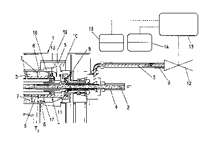
Figure 2 illustrates an advantageous way of working up the
emulsion which is formed in the solvent extraction during
the hydrometallurgical winning of a metal, as shown in
figure 1.
CA 02876564 2014-12-12
- 7 -
Particular preference is given to using a decanter, in
particular a three-phase decanter, for working up the
emulsion.
In the case of the three-phase decanter 1 shown in
figure 2, emulsion 2 to be worked up is introduced via a
feed tube 4 into a drum interior 3 of a drum 16.
This emulsion 2 is separated in the centrifugal field of
the drum 16 of the decanter 1 into an organic phase 5, an
aqueous phase 6 and a solids phase 7. A separation zone
diameter T and a pond depth or a pond depth diameter TD are
formed.
The organic phase 5 is discharged from the decanter 1 via a
peeling plate 8 with peeling plate shaft and an outflow
line 9 arranged downstream of this by means of a pump (not
shown).
The heavier aqueous phase 6 is, by way of example,
discharged radially from the decanter interior 3 at an
outlet 19, collected in the collection space 10 and from
there discharged from the decanter.
The solids phase 7 is preferably conveyed by means of a
screw 17 on a side of the drum 16 opposite the outlet for
the organic phase 5 and there discharged from the drum 16
(not shown).
A weir 11 via which the organic phase 5 flows to the
peeling plate 8 is arranged in the drum interior 3.
CA 02876564 2014-12-12
- 8 -
The weir 18 serves, in contrast, as discharge overflow for
the aqueous phase 7 to the preferably radial outlet from
the drum 16.
To set the separation zone or the separation zone diameter
T (see also figures 3 and 4) in the decanter 1, a valve 12
installed in the outflow line 9 is switched; this valve 12
can be controlled via a regulating device 13 for adjusting
the valve 12 as a function of a process parameter, in
particular as a function of the pressure of the organic
phase.
This regulating device 13 has at least one means for
determining a process parameter. A preferred means for
determining the process parameter is preferably a means for
density measurement 14, in particular for measuring the
density of the organic phase 5.
If the density deviates from a guide parameter (preferably
a fixed or variable prescribed density value which reflects
a maximum contamination of the organic phase 5) or a
prescribed density value associated therewith, the degree
of throttling of the value 12 is altered appropriately.
Increased throttling of the valve 12 results in less light
phase 5 being discharged, as a result of which the diameter
of the separation zone T in the drum 16 of the decanter is
shifted outward and at the same time the pond depth DT is
increased radially in an inward direction.
The adjustment of the outflow pressure associated with
adjustment of the valve 12 brings about a shift of the
separation zone T in the decanter as a function of the
density of the organic phase. An increase in the density of
CA 02876564 2014-12-12
- 9 -
the organic phase is equivalent to an increase in
contamination of this phase. Determination of the density
makes it possible to detect contamination in the organic
phase 5 in a simple way. A fixed or variable prescribed
value for the density gives the upper limit for possible
contamination. If this is exceeded, countermeasures for
reducing the density are undertaken, e.g. altering the
outflow pressure in the outflow line 9. Determination of
the density thus allows automatic adaptation of the mode of
operation of the decanter in continuous operation.
Figure 3 shows a possible state of the decanter 1 in which
the valve 12 (not shown here) has not been throttled or
throttled only very slightly. In this state, the organic
phase is present in only a very small amount.
If the contamination of the valuable organic phase
increases, this increased contamination can be determined
by the means shown in figure 2 for density measurement 14,
e.g. in the outflow line 9, and the valve 12 can
subsequently be throttled to increase the outflow pressure.
The increased outflow pressure shifts the separation zone T
outward, so that a smaller amount of solids is present in
the region of the outflow for the organic phase and the
aqueous phase. In addition, the pond zone diameter TD moves
radially inward. Figure 4 shows the state of the decanter 1
in the case of a more greatly throttled pressure valve 12
compared to figure 3, in which state the outflow pressure
is increased, which shifts the separation zone T further
outward and the pond depth TD inward.
The graph in figure 5 schematically shows the dependence of
the ratio of separation zone diameter T/drum diameter on
the ratio of pond depth Td/drum diameter.
CA 02876564 2014-12-12
- 10 -
The graph in figure 6 describes the dependence of the
density of the contaminated organic phase on the degree of
contamination. A pure organic phase has a density of
845 kg/m3. However, this density increases further,
preferably linearly, with increasing contamination. A
direct conclusion as to the prevailing contamination can
therefore be drawn by determining the density of the
organic phase.
Such a graph is determined experimentally. The outlet
pressure which is particularly advantageous at a given
contamination is also determined in the experiment. Such a
relationship can then be stored in the computer and
employed for determining the outflow pressure to be set.
Thus, the graph of figure 7 shows the dependence of the
separation zone diameter to the drum diameter T on the
pressure at the peeling plate or centripetal pump as a
result of throttling of the valve 12.
It can be seen that when the pressure generated by the pump
increases, the separation zone diameter T increases in an
outward direction. The increase in the separation zone
diameter T corresponds to an increase in the volume of
organic phase in the drum and thus an increase in the
retention time, i.e. the time which the organic phase takes
to run through the decanter.
The increase in the separation zone diameter T thus also
results in a higher purity of the organic phase. The
adaptation of the outflow pressure and, associated
therewith, the separation zone diameter T as a function of
CA 02876564 2014-12-12
- 11 -
the measured density of the organic phase can be carried
out in real time in a continuous process.
However, if the outflow pressure increases too greatly, for
example as a result of a large reduction in the outflow
volume of the organic phase, an organic phase having a high
purity is obtained but in this case part of the organic
phase is lost during discharge of the aqueous phase. Solids
are sometimes also lost in this way. In this case, an
additional determination and adjustment of the yield, the
conductivity and the purity of the organic phase or
optionally also the aqueous phase can be carried out. The
yield can, for example, be determined using means for
measuring the volume flow 15, which means are, as shown in
figure 2, arranged in the region of the outlet for the
organic phase.
It should be noted that suitable means for measuring the
density are known to those skilled in the art. Mention may
be made of optical methods (shining light through the
phase: increase in turbidity indicates an increase in
density). Furthermore, other suitable means for density
measurement can be employed. The density measurement is
preferably carried out continuously, for example on the
product exiting from the outflow line 9.
The experiments were carried out using a decanter
centrifuge model DCE 345-02.32 from GSA WESTFALIA GROUP
GMBH, Oelde, Germany.
CA 02876564 2014-12-12
- 12 -
Reference numerals
1 Decanter
2 Emulsion
3 Decanter interior
4 Feed tube
Organic phase
6 Aqueous phase
7 Solids phase
8 Peeling plate
9 Outflow line
Collection space
11 Weir
12 Valve
13 Regulator
14 Means for density measurement
Means for measuring the volume flow
16 Drum
17 Screw
18 Overflow weir
19 Outlet
Step A Provision of metal ore
Step 13 Leaching
Step C Solvent extraction
Step D Backextraction
Step E Electrochemical winning
Step F Work-up of the emulsion
Metal
Separation zone
Td Pond depth