Note: Descriptions are shown in the official language in which they were submitted.
CA 02876680 2014-12-15
VANE-TYPE FLUID TRANSMISSION DEVICE
FIELD OF THE INVENTION
The present invention relates to a fluid transmission
device, and more particularly, to a vane-type fluid transmission
device.
BACKGROUND OF THE INVENTION
The conventional vane-type pump generally comprises a
stator, a rotor and at least one blade, wherein the stator has a
room defined therein. The stator has an inlet and an outlet so that
the room communicates with outside of the stator. Fluid enters into
the room via the inlet and leaves the room via the outlet. The rotor
is eccentrically located in the room and the outer periphery of the
rotor is in contact with the inner periphery of the room. Multiple
blades are taken as an example. The rotor has slots for
accommodating the blades therein. The blades each have one end
pointing the center of the rotor and the other end of each of the
blades is in contact with the inner periphery of the room. A space is
defined between the inner periphery of the room and the outer
periphery of the rotor. By the contact between the rotor, the blades
and the inner periphery of the room, multiple partitions are defined
to receive fluid.
1
CA 02876680 2014-12-15
When the rotor rotates back and forth, the blades are
driven by the rotor and movable back and forth within the slots due
to the movement of the rotor. The volumes of the partitions vary
due to the back-and-forth movement of the blades, so that the fluid
is sucked into the room via the inlet and leaved from the room via
the outlet.
The centrifugal force generated from the blades due to the
rotation of the rotor drives the blades outward so as to contact the
distal ends of the blades with the inner periphery of the room to
pump the fluid. However, when the viscosity of the fluid is high,
there will be a gap between the distal ends and the inner periphery
of the room and the transmission efficiency of the fluid is reduced.
US4212603, US5087183, US5160252, US5181843 and
US5558511 respectively discloses a fluid transmission device
which comprises a stator with an annular groove which shares a
common center with the room. The axles of the blades are
engaged with the annular groove which guides the movement of
the blades. The rotor is eccentrically located in the room and the
axis of each of the blades points the center of the rotor, so that the
shape of the inner periphery of the room is like oval inner periphery
which is difficult to be machined during manufacturing processes.
Furthermore, the blades each have a certain thickness, in order to
2
CA 02876680 2014-12-15
prevent interference between two adjacent distal ends of the
blades and the inner periphery of the room, the distal end of each
blade is made to be sharpened. The sharp distal end of the blade
may vibrate when the fluid passes therethrough and noise is
therefore generated. The vibration also generates partial therm
stress which accelerates fatigue of the material at the distal end of
the blade.
In view of the above, after repeated trials and experiments,
the Applicant develops, researches for and thus provides a solution
having novelty and inventive step, as disclosed by application.
SUMMARY OF THE INVENTION
It is a primary object of the present invention to provide a
vane-type fluid transmission device. In the vane-
type fluid
transmission device, a rotor is eccentrically disposed in a circular
room, axles of blades are pivotably connected to pieces that are
rotatably movable regarding a center of the room as a rotation
center. The blades
and the pieces form relative rotation
movements. Adapted to a shape of ends of the blades, the
blades are kept in a tangential contact with an inner wall of the
room. Accordingly, pumping and transmission efficiency of a fluid
is increased, and complications for processing the stator to form
the room are reduced.
3
CA 02876680 2014-12-15
It is another object of the present invention to provide a
vane-type fluid transmission device, which is can utilize an inverter
motor to connected the shaft of the rotor to control the flow rate of
the fluid.
To achieve the objects above-mentioned, the present
invention relates to a fluid transmission device and comprises a
stator having a room defined therein and the room has a circular
inner periphery, the stator has an inlet and an outlet, the inlet and
the outlet communicate with the room; a rotor has a cylindrical
body and a shaft extends through the cylindrical body, the
cylindrical body is eccentrically located in the room and the outer
periphery of the cylindrical body is tangent to the inner periphery of
the room, the inlet and the outlet are respectively located adjacent
to the position where the outer periphery of the cylindrical body is
tangent to the inner periphery of the room, two slots are defined
diametrically in the outer periphery of the cylindrical body and
communicate with the room; the shaft extends through the stator
and is connected with a power source; two blades are respectively
located within the slots, the first end of each blade points the axis
of the cylindrical body and the second end of each blade is in
contact with the inner periphery of the room so as to form a space
for receiving fluid between the outer periphery of the cylindrical
4
CA 02876680 2014-12-15
body and the inner periphery of the room; two first pieces and two
second pieces are respectively pivotably connected to the stator,
wherein the first pieces are located adjacent to the inner bottom of
the cylindrical body and the second pieces are located adjacent to
the inner top of the cylindrical body, the first pieces and the second
pieces are pivoted about the center of the room, the two blades
are respectively and pivotably connected to the first pieces and the
second pieces by two respective axles, the blades are pivotable
about the center of the room and linearly movable within the slots;
a curved face is defined in the second end of each of the two
blades and in contact with the inner periphery of the room, the
inner periphery of the room has a radius R1, each of the axles is
pivotable by a radius R2, the curved face of the second end of
each of the two blades has a radius R3. R3=R1-R2, the two blades
and the first pieces are pivoted about two respective centers of the
curved faces such that the second ends of the two blades are in
contact with the inner periphery of the room.
The present invention a vane-type fluid transmission
device, wherein the stator has a circular first recess and a circular
second recess, the first and second recesses share the center with
the room, the first pieces are respectively engaged with the first
recess and the second pieces are respectively engaged with the
5
CA 02876680 2014-12-15
second recess, the first and second pieces are pivoted about the
center of the room.
The present invention a vane-type fluid transmission
device, wherein the first recess of the stator has a first dim in an
inner end thereof and the second recess of the stator has a
second dim in an inner end thereof.
The present invention a vane-type fluid transmission
device, wherein a first protrusion extends from a center of the first
recess and shares the center with the room, a second protrusion
extends from a center of the second recess and shares the center
with the room.
The present invention a vane-type fluid transmission
device, wherein each of the first and second pieces comprises a
ring and a protrusion, the rings of the first pieces are mounted to
the first protrusion and the rings of the second pieces are mounted
to the second protrusion.
The present invention a vane-type fluid transmission
device, wherein each of the first and second pieces are curved
plates and an arc of each of the first and second pieces is over
180 degrees, each of the first pieces is pivotably connected to the
first protrusion and each of the second piecesis pivotably
connected to the second protrusion.
6
CA 02876680 2014-12-15
The present invention a vane-type fluid transmission
device, wherein each of the first and second pieces comprises a
ring and a protrusion which is connected to an inner periphery of
the ring, the protrusion is a curved protrusion, the protrusion of ring
of each of the first pieces is in contact with the first protrusion, an
outer periphery of the ring of each of the first pieces is in contact
with an inner wall of the first recess, the protrusion of ring of each
of the second pieces is in contact with the second protrusion, an
outer periphery of the ring of each of the second pieces is in
contact with an inner wall of the second recess.
The present invention a vane-type fluid transmission
device, wherein the two blades are pivotably connected to the
protrusions of the first and second pieces by the axles.
The present invention a vane-type fluid transmission
device, wherein a groove is defined in an end face of the
cylindrical body and two ends of the groove respectively
communicate with the slots, the two ends of the groove are located
close to the shaft.
The present invention a vane-type fluid transmission
device, wherein the stator comprises a base and a cover.
The present invention a vane-type fluid transmission
device, wherein the shaft is connected with an inverter motor.
7
CA 02876680 2014-12-15
The present invention a vane-type fluid transmission
device, comprising a stator, a rotor, a blade, a first piece and a
second piece, wherein the stator having a room defined therein
and the room having a circular inner periphery, the stator having an
inlet and an outlet, the inlet and the outlet communicating with the
room;
the rotor having a cylindrical body and a shaft which
extends through the cylindrical body, the cylindrical body
eccentrically located in the room, an outer periphery of the
cylindrical body being tangent to the inner periphery of the room,
the inlet and the outlet respectively located adjacent to a position
where the outer periphery of the cylindrical body is tangent to the
inner periphery of the room, a slot defined radially in the outer
periphery of the cylindrical body and communicating with the room,
the shaft extending through the stator and adapted to be
connected with a power source;
the blade located within the slot, a first end of the blade
pointing an axis of the cylindrical body, a second end of the blade
being in contact with the inner periphery of the room so as to form
a space for receiving fluid between the outer periphery of the
cylindrical body and the inner periphery of the room;
8
CA 02876680 2014-12-15
the first piece and the second piece respectively and
pivotably connected to the stator, the first piece being located
adjacent to an inner bottom of the cylindrical body and the second
piece being located adjacent to an inner top of the cylindrical body,
the first piece and the second piece pivoted about a center of the
room, and the blade pivotably connected to the first piece and the
second piece by an axle, the blade being pivotable about the
center of the room and linearly movable within the slot, a curved
face defined in the second end of the blade and being in contact
with the inner periphery of the room, the inner periphery of the
room having a radius R1, the axle being pivotable by a radius R2,
the curved face of the second end of the blade having a radius R3,
R3=R1-R2, the blade and the first piece being pivoted about the
center of the curved face such that the second end of the blade is
in contact with the inner periphery of the room.
The present invention a vane-type fluid transmission
device, wherein the each of the inlet and the outlet is connected
with a check valve so as to control the direction that the fluid
passes through the stator.
The present invention a vane-type fluid transmission
device, comprising a stator, a rotor, a first blade, a second blade, a
first piece and a second piece, wherein the stator having a room
9
CA 02876680 2014-12-15
defined therein and the room having a circular inner periphery, the
stator having an inlet and an outlet, the inlet and the outlet
communicating with the room;
the rotor having a cylindrical body and a shaft which
extends through the cylindrical body, the cylindrical body
eccentrically located in the room, an outer periphery of the
cylindrical body being tangent to the inner periphery of the room,
the inlet and the outlet respectively located adjacent to a position
where the outer periphery of the cylindrical body is tangent to the
inner periphery of the room, two slots defined diametrically in the
outer periphery of the cylindrical body and respectively
communicating with the room, the shaft extending through the
stator and adapted to be connected with a power source;
the first blade and the second blade located within the
slots respectively, a first end of each of the first and second blades
pointing an axis of the cylindrical body, a second end of each of the
first and second blades being in contact with the inner periphery of
the room so as to form a space for receiving fluid between the
outer periphery of the cylindrical body and the inner periphery of
the room;
the first piece and the second piece respectively and
pivotably connected to the stator, the first piece being located
CA 02876680 2014-12-15
adjacent to an inner bottom of the cylindrical body and the second
piece being located adjacent to an inner top of the cylindrical body,
the first piece and the second piece pivoted about a center of the
room, the first and second pieces respectively form a pivotal hole
and a circular guide slot;
the first blade pivotably connected to an axle and two
ends of the axle pivotably connected with the pivotal holes of the
first and second pieces, the second blade pivotably connected to a
first axle and a second axle, the first axle connected to a first slide
and the second axle connected to a second slide, the first slide
slidably inserted into the guide slot of the first piece and the
second slide slidably inserted into the guide slot of the second
piece, the first and second blades pivotable about the center of the
room, the first and second blades movable within the guide slots,
and
a curved face defined in the second end of the first blade
and being in contact with the inner periphery of the room, a curved
face defined in the second end of the second blade and being in
contact with the inner periphery of the room, the inner periphery of
the room having a radius R1, the axle and the first and second
axles being pivotable by a radius R2, the curved faces of the first
and second blade having a radius R3, R3=R1-R2, a center of the
11
CA 02876680 2014-12-15
curved face located at a center of the axle, a center of the curved
face located at a center of the first and second axles, the second
ends of the first and second blades being in contact with the inner
periphery of the room.
The present invention a vane-type fluid transmission
device, wherein the pivotal hole and the guide slot are defined in a
first side of the first piece, a second side of the first piece is a
closed side, the pivotal hole and the guide slot are defined in a first
side of the second piece, a second side of the second piece is a
closed side.
The present invention a vane-type fluid transmission
device, wherein the pivotal hole and the guide slot are defined
through the first piece, the pivotal hole and the guide slot are
defined through the second piece.
Therefore, the efficiency of transmission of the fluid is
increased and the manufacturing processes for making the room
are simplified, the present invention can utilize an inverter motor to
connect the shaft of the rotor to control the flow rate of the fluid.
BRIEF DESCRIPTION OF THE DRAWINGS
Fig. 1 is a perspective view to show the fluid transmission device
of the present invention;
12
CA 02876680 2014-12-15
Fig. 2 is an exploded view to show the fluid transmission device of
the present invention;
Fig. 3 is a top view of the base of the fluid transmission device of
the present invention;
Fig. 4 is a cross sectional view taken along line 4-4 in Fig. 3;
Fig. 5 is a cross sectional view of the cover of the fluid
transmission device of the present invention;
Fig. 6 is a cross sectional view of the fluid transmission device of
the
present invention;
Fig. 7 is a top view to show the fluid transmission device of the
present invention, wherein the cover is removed;
Fig. 8 is an operational status of the fluid transmission device of
the present invention;
Fig. 9 is another operational status of the fluid transmission device
of the present invention;
Fig. 10 is a cross sectional view of the second embodiment of the
fluid transmission device of the present invention;
Fig. 11 is an exploded view to show the third embodiment of the
fluid transmission device of the present invention;
13
CA 02876680 2014-12-15
Fig. 12 is a top view to show the third embodiment of the fluid
transmission device of the present invention, wherein the cover is
removed;
Fig. 13 is an exploded view to show the first piece, the second
piece and the rotor of the fourth embodiment of the fluid
transmission device of the present invention;
Fig. 14 is an exploded view to show the first piece, the second
piece and the rotor of the fifth embodiment of the fluid transmission
device of the present invention;
Fig. 15 is an exploded view to show the sixth embodiment of the
fluid transmission device of the present invention;
Fig. 16 is an exploded view to show the seventh embodiment of
the fluid transmission device of the present invention;
Fig. 17 is an axial cross sectional view of the first piece in the
seventh embodiment of the fluid transmission device of the present
invention, and
Fig. 18 is an axial cross sectional view of the second piece in the
seventh embodiment of the fluid transmission device of the present
invention.
14
CA 02876680 2014-12-15
DETAILED DESCRIPTION OF THE PREFERRED
EMBODIMENTS
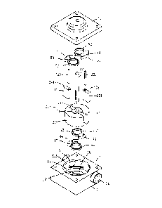
Referring to Figs. 1 and 2, the fluid transmission device of
the present invention comprises a stator 10, a rotor 20, two blades
32, 34, two first pieces 40 and two second pieces 50. The stator 10
comprises a base 11 and a cover 12 which is connected to the
base 11. A sealing member (not shown) may be connected
between the base 11 and the cover 12, and multiple bolts (not
shown) are used to connect the base 11 and the cover 12. As
shown in Figs. 3 and 4, the stator 10 has a room 13 defined
therein and the room 13 has a circular inner periphery 132. The
stator 10 has an inlet 14 and an outlet 15. The inlet 14 and the
outlet 15 communicate with the room 13 and outside of the stator
10. The stator 10 has a circular first recess 16 defined in the inner
top of the room 13. A first protrusion 17 extends from the center of
the first recess 16 and shares the center with the room 13. As
shown in Fig. 5, the cover 12 has a second recess 18 defined in
the underside thereof and faces the room 13. A second protrusion
19 extends from the center of the second recess 18 and shares
the center with the room 13.
As shown in Figs. 2 to 7, the rotor 20 has a cylindrical
body 21 and a shaft 22 which extends through the cylindrical body
CA 02876680 2014-12-15
21. The cylindrical body 21 is eccentrically located in the room 13
and the outer periphery of the cylindrical body 21 is tangent to the
inner periphery 132 of the room 13. The inlet 14 and the outlet 15
are respectively located adjacent to the position where the outer
periphery of the cylindrical body 21 is tangent to the inner
periphery 132 of the room 13. The shaft 22 has one end pivotably
connected to the base 11 and the other end of the shaft 22 extends
through the stator 10 so as to be connected with a power source
such as a motor or an inverter motor (not shown). The shaft 22 is
pivotably connected with a plurality of bearings or bushes (not
shown) and the bearings are connected to the base 11 and the
cover 12 so allow the shaft 22 to be rotated smoothly. Two slots 23
are defined diametrically in the outer periphery of the cylindrical
body 21. One end of each of the slots 23 points the center of the
cylindrical body 21 and the other end of each of the slots 23
communicates with the room 13. A groove 24 is defined in the end
face of the cylindrical body 21 and two ends of the groove 24
respectively communicate with the slots 23. The two ends of the
groove 24 are located close to the shaft 22.
The two blades 32, 34 are respectively located within the
slots 23. The first end of each blade 32/34 points the axis of the
cylindrical body 21, and the second end of each blade 32/34 is in
16
CA 02876680 2014-12-15
contact with the inner periphery 132 of the room 13 so as to form a
space for receiving fluid between the outer periphery of the
cylindrical body 21 and the inner periphery 132 of the room 13.
The first pieces 40 and two second pieces 50 are
respectively pivotably connected to the stator 10. The first pieces
40 are located adjacent to the inner bottom of the cylindrical body
21 and the second pieces 50 are located adjacent to the inner top
of the cylindrical body 21. The first pieces 40 and the second
pieces 50 are pivoted about the center of the room 13. Each of the
first and second pieces 40, 50 comprises a ring 42/52 and a
protrusion 44/54. The protrusion 44/54 is a curved protrusion and
connected to the outer periphery of the ring 42/52. The first pieces
40 are pivotably connected to the first recess 16 so that the first
pieces 40 are adjacent to the underside of the cylindrical body 21.
The rings 42 of the first pieces 40 are mounted to the first
protrusion 17 so that the first pieces 40 are pivotabie about the
center of the room 13. The second pieces 50 are pivotably
connected to the second recess 18 so that the second pieces 50
are adjacent to the top of the cylindrical body 21. The rings 52 of
the second pieces 50 are mounted to the second protrusion 19 so
that the second pieces 50 are pivotable about the center of the
room 13. The two blades 32, 34 are respectively and pivotably
17
CA 02876680 2014-12-15
connected to the first pieces 40 and the second pieces 50 by two
respective axles 322, 342. Two ends of the axle 342 are pivotably
connected to the protrusions 44, 54 of the first and second pieces
40, 50. When the rotor 20 rotates, the first and second pieces 40,
50 drive the axles 322, 342 to make the blades 32, 34 be pivoted
about the center of the room 13. In the meanwhile, the blades 32,
34 are linearly movable in the slots 23. The rings 42 are mounted
to the first protrusion 17 so that when the first pieces 40 rotate,
there will be no interference between the first pieces 40 and the
first protrusion 17. Therefore, the rotation of the first pieces 40 is
reliable. The rings 52 are mounted to the second protrusion 19 so
that when the second pieces 50 rotate, there will be no
interference between the second pieces 50 and the second
protrusion 19. Therefore, the rotation of the second pieces 50 is
reliable.
A curved face 324/344 is defined in the second end of
each of the two blades 32, 34 and in contact with the inner
periphery 132 of the room 13. The inner periphery 132 of the room
13 has a radius R1. Each of the axles 322, 342 is pivotable by a
radius R2. The curved face 324/344 of the second end of each of
the two blades 32, 34 has a radius R3. The relationship of the
three radiuses can be expressed by the equation R3=R1-R2. The
18
CA 02876680 2014-12-15
two blades 32, 34 and the first pieces 40 are pivoted about two
respective centers of the curved faces 324, 344 (the axes of the
axles 322, 342) such that the second ends of the two blades 32,
34 are in contact with the inner periphery 132 of the room 13.
Therefore, the efficiency of transmission of the fluid is increased
and the manufacturing processes for making the room 13 are
simplified.
A power source (not shown) is connected to the shaft 22
to
rotate the rotor 20, the blades 32, 34 are rotated about the center
of the room 13 and, the blades 32, 34 are respectively rotated
relative to the first and second pieces 40, 50. The blades 32, 34
are moved along the slots 23. When the rotor 20 rotates clockwise,
as shown in Figs. 8 and 9, the space for receiving fluid in the room
13 are varied along with the rotation of the rotor 20 in the room 13,
such that the fluid is sucked into the room 13 via the inlet 14 and
the fluid is transmitted by the blades 32, 34 and then flows out
from the outlet 15. When the rotor 20 rotates counter-clockwise,
the fluid is sucked into the room 13 via the outlet 15 and the fluid is
transmitted by the blades 32, 34 and then flows out from the inlet
14. Therefore, by controlling the direction of rotation of the rotor 20,
the fluid can be transmitted in desired direction.
19
CA 02876680 2014-12-15
When the rotor 20 rotates, the blades 32, 34 are rotated
about the respective axles 322, 342, and the axles 322, 342 move
circularly about the center of the room 13 By cooperation of the
radius R3 of the curved faces 324, 344, the curved faces 324, 344
of the blades 32, 34 are in contact with the inner periphery 132 of
the room 13 without interference so as to increase the efficiency of
transmission of fluid. The inner periphery 132 of the room 13 is
around inner periphery which reduces the difficulties of machining.
Furthermore, when the blades 32, 34 move in the slots 23 back
and forth, because the first ends of the two blades 32, 34 point the
center of the room 13, and the two slots 23 are in communication
with each other via the grooves 24, so that the fluid within the
space between the two respective first ends of the blades 32, 34
and the shaft 22 flows between the two slots 23 via the grooves 24.
This avoids the positive/negative pressure applied to the two
blades 32, 34 so that the blades 32, 34 move smoothly.
The number of the blades 32, 34 can be three or more
than three, and the number of the pieces 40, 50 is also changed
along with the change of the blades 32, 34. The number of the
slots 23 is correspondingly changed to accommodate the blades
32, 34.
CA 02876680 2014-12-15
Fig. 10 shows the second embodiment, the differences
between the first and second embodiments are that each of the
first recesses 16 of the stator 10 has a first dim 162 in the inner
end thereof so as to reduce the contact area between the first
pieces 40 and the first recesses 16 and reduce the friction
between the first pieces 40 and the base 11. Each of the second
recess 18 of the stator 10 has a second dim 182 in the inner end
thereof so as to reduce the contact area between the second
pieces 50 and the second recesses 18 and reduce the friction
between the second pieces 50 and the base 11. Lubricant is
received in each of the first and second dims 162, 182.
Figs. 11 and 12 show the third embodiment which
comprises a stator 10, a rotor 20, a blade 32, a first piece 40 and a
second piece 50. The differences between the first and third
embodiments are that the slot 23 is defined radially in the outer
periphery of the cylindrical body 21 and communicates with the
room 13. The blade 32 is movable in the slot 23.
Each of the inlet 14 and the outlet '15 has a check valve
(not shown) connected thereto so as to control the direction of the
fluid.
Fig. 13 shows the fourth embodiment wherein the
differences between the first and fourth embodiments are that each
21
CA 02876680 2014-12-15
of the first and second pieces 40, 50 are curved plates and an arc
of each of the first and second pieces 40, 50 is over 180 degrees.
Each of the first pieces 40 is pivotably connected to the first
protrusion (not shown) of the stator (not shown) and each of the
second pieces 50 is pivotably connected to the second protrusion
(not shown) of the stator (not shown). The blade 32 is connected to
an axle 322 which is pivotably connected between the first and
second pieces 40, 50. The blade 34 is connected to an axle 342
which is pivotably connected between the first and second pieces
40, 50. When the rotor 20 rotates, the first and second pieces 40,
50 drive the blades 32, 34 by the axles 322, 342 and the blades 32,
34 rotate about the center of the room 13. The blades 32, 34 move
along the slots 23 back and forth. Because the arc of each of the
first and second pieces 40, 50 is over 180 degrees, the rotation of
the first and second pieces 40, 50 is reliable.
Fig. 14 shows the fifth embodiment of the present
invention, wherein the differences between the first and fifth
embodiments are that each of the first and second pieces 40, 50
comprises a ring 42/52 and a protrusion 44/54. The protrusion
44/54 is connected to the inner periphery of the ring 42/52. The
protrusion 44/54 is a curved protrusion. The protrusion 44 of ring
42 of each of the first pieces 40 is in contact with the outer
22
CA 02876680 2014-12-15
periphery of the first protrusion (not shown) of the stator (not
shown). The outer periphery of the ring 42 of each of the first
pieces 40 is in contact with the inner wall of the first recess 16. The
protrusion 54 of ring 52 of each of the second pieces 50 is in
contact with the outer periphery of the second protrusion (not
shown) of the stator (not shown). The outer periphery of the ring 54
of each of the second pieces 50 is in contact with the inner wall of
the second recess. The first and second pieces 40, 50 respectively
rotate about the center of the room '13, because the outer
periphery of the ring 44/54 is in contact with the inner periphery of
the first/second recess, so that the rotation of the first and second
pieces 40, 50 are reliable. The blade 32 is connected to an axle
322 which is pivotably connected between the protrusions 44, 54
of the first and second pieces 40, 50. The blade 34 is connected to
an axle 342 which is pivotably connected between the protrusion
44, 54 of the other two first and second pieces 40, 50. When the
rotor 20 rotates, the first and second pieces 40, 50 drive the blades
32, 34 by the axles 322, 342 and the blades 32, 34 rotate about
the center of the room 13. The blades 32, 34 move along the slots
23 back and forth.
Fig. 15 shows the sixth embodiment of the present
invention and comprises a stator 10, a rotor 20, a first blade 36, a
23
CA 02876680 2014-12-15
second blade 38, a first piece 40 and a second piece 50. The
differences between the first and sixth embodiments are that the
first and second pieces 40, 50 are ring-shaped pieces and the first
pieces 40 are mounted to the first protrusion 17 and the second
pieces 50 are mounted to the second protrusion (not shown). The
first piece 40 and the second piece 50 are pivoted about the center
of the room 13. The first and second pieces 40, 50 respectively
form a pivotal hole 46/56 and a circular guide slot 48/58. The first
blade 36 is pivotably connected to an axle 362 and two ends of the
axle 362 are pivotably connected with the pivotal holes 46, 56 of
the first and second pieces 40, 50. The first and second pieces 40,
50 drive the first blade 36 to pivot about the center of the room 13
by the axle 362. The second blade 38 is pivotably connected to a
first axle 382 and a second axle 384. The first axle 382 is
connected to a first slide 386 and the second axle 384 is
connected to a second slide 388. The first slide 386 is slidably
inserted into the guide slot 48 of the first piece 40 and the second
slide 388 is slidably inserted to the guide slot 58 of the second
piece 50. The first and second pieces 40, 50 drive the first and
second axes 382, 384 to rotate the second blade 38 to be
pivotable about the center of the room 13. The first and second
24
CA 02876680 2014-12-15
slides 386, 388 are movable along with the guide slots 48, 58 back
and forth.
Fig. 16 shows the seventh embodiment which is amended
from the fifth embodiment, wherein the first and second pieces 40,
50 are located symmetrically relative to the cylindrical body 21. As
shown in Fig. 17, the first piece 40 has a pivotal hole 46 and a
curved guide slot 48. The pivotal hole 46 and the guide slot 48 are
defined in the first side of the first piece 40, the second side of the
first piece 40 is a closed side. As shown in Fig. 18, the second
piece 50 has a pivotal hole 56 and a curved guide slot 58. The
pivotal hole 56 and the guide slot 58 are defined in the first side of
the second piece 50, and the second side of the second piece 50
is a closed side.
The embodiments described in the above can utilize an
inverter motor to connect the shaft of the rotor to control the flow
rate of the fluid.
While inventor have shown and described the
embodiment in accordance with the present invention, it should be
clear to those skilled in the art that further embodiments may be
made without departing from the scope of the present invention.