Note: Descriptions are shown in the official language in which they were submitted.
WO 2013/187960
PCT/US2013/030289
CARBON BAKING OXYGEN PREHEAT AND HEAT RECOVERY FIRING
SYSTEM
100011 This application claims the benefit of priority to U.S. provisional
application
having serial no. 61/660,465, filed on June 15, 2012.
Field of the Invention
[0002] The field of the invention is devices and methods for increasing
thermal
efficiency in furnaces, and especially in ring furnaces for carbon baking
operations.
Background
100031 Carbon baking furnaces, and particularly ring furnaces, are often used
in the
manufacture of carbon anodes for the aluminum smelting processes. Due to the
high
temperatures and long baking times, anode baking requires substantial
quantities of
energy and has become a significant contributor to production cost. Moreover,
due to
the often relatively low oxygen content in the furnace, pitch is not
completely combusted
and tends to lead to fires, variations in operating conditions, and
maintenance issues for
downstream scrubber systems.
100041 Numerous ring furnaces for carbon baking and methods of operating same
are
known in the art, and exemplary devices and methods are described, for
example, in WO
02/099350, U.S. Pat. Nos. 4,215,982, 4,284,404, and 6,339,729, GB 116455, EP 0
541
165, and W09855426A1. Computer-control of firing rates for burners is
disclosed in
U.S. Pat. No. 6,436,335, and U.S. Pat. Nos. 4,253,823 teaches use of a water
spray/vapor
to increase heat transfer between the cooling gas and baked carbon electrodes.
These and
all other extrinsic materials discussed herein are incorporated by reference
in their
entirety. Where a definition or use of a term in an incorporated reference is
inconsistent
or contrary to the definition of that term provided herein, the definition of
that term
provided herein applies and the definition of that term in the reference does
not apply.
[0005] While most of these known furnaces are satisfactory for a particular
operation,
they often tend to limit their use to baking of materials within relatively
small
dimensional variation. To overcome such disadvantage, GB 948,038 teaches a
baking
furnace with a refractory floor and vertical metal flues to so adapt to baking
of
carbonaceous bodies of widely different sizes and shapes under conditions of
increased
thermal efficiency, increased unit capacity, and reduced furnace construction
and
CA 2876840 2018-03-05
CA 02876840 2014-12-15
WO 2013/187960 PCT/US2013/030289
operational costs. Among other configurations, the furnace of the '038
reference is
configured to allow feeding of the exhaust gas after leaving the furnace back
to the
combustion source. However, such feedback is typically not suitable for a ring
furnace.
100061 in yet another known attempt to improve energy efficiency, EP 0 158 387
teaches
heating of carbon materials in a first pre-heating stage up by use of hot
combusted
volatile matter, which is obtained by withdrawing the released volatile matter
from the
first stage, burning the volatile matter outside the first stage, and by
recycling the burnt
volatile matter to the first stage. Such configuration advantageously improves
the pre-
heating. Nevertheless, considerable amounts of energy are still required for
the firing
zone of the furnace.
100071 In still other known methods, attempts have been undertaken to
introduce
supplementary air to the preheating zone of a ring furnace to so reduce
incomplete
combustion of pitch and other undesirable side products as, for example,
described in
WO 91119147. Such approach may conceptually be attractive, however, suffers
from
various drawbacks in practice. For example, where the supplemental air enters
the flue
in the preheating zone by way of a valve using the negative pressure in the
preheating
zone flue, the zero point irray move in the furnace towards the firing zone.
To help
overcome this disadvantage, the draft rate at the preheating zone may be
increased.
However, such increase may adversely affect the temperature gradient in the
preheating
zone and may not yield desirable heating performance. Still further, the
energy gain by
introduction of supplemental air for increased combustion will be in most
cases
neutralized by a temperature drop caused by the addition of supplemental air.
Similarly,
WO 2004/027332 describes near real-time measurement of soot in the furnace and
adjusts the fuel feed rate, draft fan rate, and/or secondary air feed through
openings in the
zones of the furnace in response to the measured soot level. Notably, the '332
application appears to recognize the drawbacks of secondary air feed and
teaches that
secondary air feeds are undesirable and that proper furnace design should
eliminate the
need for secondary air feeds.
100081 Thus, even though numerous configurations and methods for carbon baking
furnaces are known in the art, there is still a need for more energy efficient
furnaces.
2
CA 02876840 2014-12-15
WO 2013/187960 PCT/US2013/030289
Summary of The Invention
100091 The inventive subject matter is drawn to various devices and methods of
recovery
of waste heat and reducing energy consumption in a furnace, and most typically
in a ring
furnace, in which a supplemental oxygen conduit is provided that allows
feeding of
heated additional oxygen to the firing andlor pre-heat zones to not only
assist in
complete combustion of the fuel araWor volatiles, hut also act as a heat
transfer medium
for waste heat in the cooling zone. Consequently, waste heat is recovered and
thus
reduces fuel demand, while at the same time oxygen content is increased, which
allows
for complete combustion of the volatiles at reduced fuel input.
100101 In one aspect of the inventive subject matter, an oxygen preheat and
heat
recovery system for use in a carbon baking furnace is contemplated that
includes a
plurality of wall elements (also known as sections), each having multiple
internal flue
channels, wherein the plurality of wall elements are fluidly coupled to each
other such
that the internal flue channels form a continuous flow path having, in
sequence, a pre-
heat zone, a firing zone, and a cooling zone. A supplemental oxygen conduit is
present
in contemplated systems that is thermally coupled to at least part of the flue
channel of
the cooling zone such that supplemental oxygen flowing in the supplemental
oxygen
conduit is isolated from hut heated by a cooling air stream flowing through
the cooling
zone. In especially preferred systems, the supplemental oxygen conduit has a
delivery
opening that delivers the supplemental oxygen stream directly (preferably not
through
one or more burners or fuel inlets) to the internal flue channel of the firing
zone and/or
the pre-heat zone.
100111 While in certain aspects of the inventive subject matter the
supplemental oxygen
conduit is formed (e.g., as a channel) within a wall section of the plurality
of wall
elements, the supplemental oxygen conduit may also be a separate conduit that
is at least
partially disposed within the flue channels of the cooling zone. Regardless of
the nature
of the conduit, it is typically preferred that one or more gates are coupled
to the
supplemental oxygen conduit and configured to direct flow of the supplemental
oxygen
stream into a desired wall element of the firing zone and/or pre-heat zone. To
automate
operation, a control system may be included that operate the gates such that
the flow to
desired wall element is maintained at desired values.
3
CA 02876840 2014-12-15
WO 2013/187960 PCT/US2013/030289
100121 In further contemplated aspects of the inventive subject matter, the
delivery
opening is configured to deliver the supplemental oxygen stream to a position
downstream of a first firing frame in the firing zone, or to a position at or
downstream of
a terminal firing frame in the firing zone, or to deliver the supplemental
oxygen stream to
the internal flue channel of the pre-heat zone. Moreover, it is typically
preferred that the
supplemental oxygen conduit is configured (or is coupled to a control device)
to allow
delivery of the supplemental oxygen stream at about an operating pressure
present in the
tiring zone and/or the pre-heat zone. The term "about" in conjunction with a
numerical
value or parameter as used herein refers to a range of 41- 10%, inclusive, of
the
numerical or parameter. For example, if the operating pressure in the preheat
zone is
about 80 kPa, the term about 80 kPa refers to a range of 72-88 kPa.
[0013] Viewed form a different perspective, the inventors also contemplate a
method for
reducing energy consumption of a furnace with a plurality of wall elements
(each having
an internal flue channel, wherein the wall elements are fluidly coupled to
each other such
that the internal flue channels form a continuous flow path to form, in
sequence, a pre-
heat zone, a firing zone, and a cooling zone) in which a plurality of gates
are operated to
configure a supplemental oxygen conduit such that at least a portion of the
supplemental
oxygen conduit is thermally coupled to at least a portion of the internal flue
channel of
the cooling zone. In another step, a supplemental oxygen stream is heated in
the
supplemental oxygen conduit using heat from a cooling air stream flowing
through the
internal flue channel of the cooling zone, and in yet another step, at least a
portion of the
heated supplemental oxygen stream is directly delivered (preferably not
through one or
more burners or fuel inlets) to the internal flue channel of the firing zone
and/or the pre-
heat zone.
100141 In particularly preferred methods, the gates are coupled to the wall
elements, and
the supplemental oxygen conduit is formed within a wall section of the
plurality of wall
elements. Most typically, the supplemental oxygen stream is heated to a
temperature of
at least 1000 "C (which may or may not be performed with a heat exchange
medium, or
by radiant heat transfer from the cooling air stream flowing through the
internal flue
channel to the supplemental oxygen stream). In some aspects of the inventive
subject
matter, it is preferred that the supplemental oxygen stream is delivered to a
position at or
downstream of a terminal firing frame in the firing zone, and that the heated
4
WO 2013/187960
PCT/US2013/030289
supplemental oxygen stream is delivered at a greater pressure than an
operating pressure
present in the firing zone and/or the pre-heat zone.
[0015] Therefore, the inventors also contemplate a method of reducing energy
consumption
of a ring furnace having a pre-heat zone, a firing zone, and a cooling zone,
in which heat
energy is recycled from the cooling zone to the pre-heat zone and/or firing
zone, and in
which the heat energy is carried from the cooling zone to the pre-heat zone
and/or firing
zone by a supplemental oxygen stream.
[0016] In such methods, the step of recycling is performed, using a
configurable conduit that
is formed in or runs through a plurality of wall elements that make up the pre-
heat zone, the
firing zone, and the cooling zone. It is also generally preferred that the
supplemental oxygen
stream is delivered at about an operating pressure present in the firing zone
and/or pre-heat
zone. While not limiting to the inventive subject matter, the supplemental
oxygen stream
may have an oxygen concentration that is greater than 21%.
[0016a] In another aspect, there is provided an oxygen preheat and heat
recovery system for
use in a carbon baking furnace, comprising: a plurality of wall elements, each
having an
internal flue channel, wherein the plurality of wall elements are fluidly
coupled to each other
such that the internal flue channels form a continuous flow path having, in
sequence, a pre-
heat zone, a firing zone, and a cooling zone; a supplemental oxygen conduit
thermally
coupled to at least a portion of the flue channel of the cooling zone such
that a supplemental
oxygen stream flowing in the supplemental oxygen conduit is isolated from and
heated by a
cooling air stream flowing through the cooling zone; and a plurality of gates
coupled to the
supplemental oxygen conduit and configured to direct flow of the supplemental
oxygen
stream into a desired wall element of the at least one of the firing zone and
the pre-heat zone;
wherein the supplemental oxygen conduit further comprises a delivery opening
that is
configured to deliver the supplemental oxygen stream directly to the internal
flue channel of
at least one of the firing zone and the pre-heat zone.
[0016b] In another aspect, there is provided a method of reducing energy
consumption of a
furnace having a plurality of wall elements, each having an internal flue
channel, wherein
the plurality of wall elements are fluidly coupled to each other such that the
internal flue
channels form a continuous flow path to form, in sequence, a pre-heat zone, a
firing zone,
and a cooling zone, comprising: operating a plurality of gates to configure a
supplemental
oxygen conduit such that at least a portion of the supplemental oxygen conduit
is thermally
coupled to at least a portion of the internal flue channel of the cooling
zone; heating a
supplemental oxygen stream in the supplemental oxygen conduit using heat from
a cooling
CA 2876840 2018-03-05
air stream flowing through the internal flue channel of the cooling zone; and
delivering at
least a portion of the heated supplemental oxygen stream directly to the
internal flue channel
of at least one of the firing zone and the pre-heat zone, wherein the
plurality of gates are
coupled to the plurality of wall elements, and wherein the supplemental oxygen
conduit is
formed within a wall section of the plurality of wall elements.
[0016c] In another aspect, there is provided A method of reducing energy
consumption of a
ring furnace having a pre-heat zone, a firing zone, and a cooling zone,
comprising: recycling
heat energy from the cooling zone to at least one of the pre-heat zone and the
firing zone,
wherein the heat energy is carried from the cooling zone to the at least one
of the pre-heat
zone and the firing zone by a supplemental oxygen stream via a supplemental
oxygen
conduit; wherein flow of the supplemental oxygen stream is directed into a
desired wall
element of the at least one of the firing zone and the pre-heat zone via a
plurality of gates
coupled to the supplemental oxygen conduit carrying the supplemental oxygen
stream.
[0017] Various objects, features, aspects and advantages of the inventive
subject matter will
become more apparent from the following detailed description of preferred
embodiments,
along with the accompanying drawing figures in which like numerals represent
like
components.
Brief Description of the Drawings
[0018] Prior art Figure 1 is a schematic of an exemplary ring furnace for
baking carbon
anodes.
[0019] Prior art Figure 2 is a partial cut-away view of the exempla*" ring
furnace of Figure
1.
[0020] Figure 3 is a schematic illustration of a ring furnace according to the
inventive
subject matter.
Detailed Description
[0021] The inventors have discovered that a carbon baking ring furnace can be
equipped
with a supplemental oxygen conduit that is configured to also allow recycling
of waste heat
from the cooling zone to the firing and/or preheat zone system to so
significantly reduce fuel
(e.g., natural gas), in many cases up to 25% to 40% reduction, while at the
5A
CA 2876840 2018-03-05
CA 02876840 2014-12-15
WO 2013/187960 PCT/US2013/030289
same time allowing for complete combustion of volatiles and pitch. Most
notably,
contemplated systems and methods unify two distinct parameters that would
otherwise
be irreconcilable: reduction in fuel consumption and increase in combustion of
volatiles
and pitch. In addition, the inventors discovered that use of a supplemental
oxygen
conduit as provided herein advantageously allows for draft reduction in the
furnace,
which in turn reduces energy and maintenance demand for the draft fans, as
well as
reduces energy requirements for downstream scrubbers (where installed).
100221 Of course, it should be appreciated that the zones as referred to
herein are not
positionally fixed zones, but (typically identically configured) zones that
are operated as
pre-heating, firing, and cooling zones as a function of the position of the
cooling
manifold, firing frame, and exhaust manifold. Moreover, it should be noted
that each of
the pre-heating, firing, and cooling zones will have a plurality of sections.
Thus, in most
typical embodiments, each zone and/or section will comprise a plurality of
wall
elements, each having an internal flue channel, wherein the plurality of wall
elements are
fluidly coupled to each other such that the internal flue channels form a
continuous flow
path to form, in sequence, the pre-heat zone, the firing zone, and the cooling
zone. A
firing unit is then operationally coupled to at least one wall element (of a
single section
or zone) and configured to provide fuel (e.g., natural gas, syrtgas, or other
hydrocarbon
fuel) to the firing zone, while the cooling and exhaust manifolds are
positioned
appropriately upstream and downstream of the firing unit.
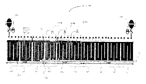
100231 Prior art Figure I schematically illustrates an exemplary ring furnace
100 having
two parallel trains of sections (e.g., 1-16) that are fluidly coupled by a
crossover to form
a ring furnace (it should be noted that the preheat, firing, and cooling zones
rotate around
the furnace). As the firing zone advances, anodes are removed and added in
sections in
advance of the tiring zone to so allow continuous operation of the furnace
runs. In the
bake furnace 100 of Prior Art Figure 1, there are two firing zones 120 moving
in counter
clockwise direction with each advance. An advance increments the process one
section
at a time around the furnace. The firing frame 122 (only one labeled), preheat
zones 130,
cooling zones 110, preheat (exhaust) manifold 132, and cooling manifold 112
advance
around the ring furnace with the firing zones. Stationary parts of the furnace
are the
crossover 140 and common collection side exhaust main 150 as well as the
sections,
flues, and walls. Each train has a pre-heating zone 130 and 130 with a firing
zone 120
6
CA 02876840 2014-12-15
WO 2013/187960 PCT/1JS2013/030289
and 120', one or more firing frames 122 (only one is labeled), draft frames
131 and 131',
and cooling zone 110 and 110', respectively. Crossover 140 connects the
trains, and
exhaust gas from the preheat (exhaust) manifolds 132 and 132' is delivered to
common
exhaust collection conduit 150. As used herein, and unless the context
dictates otherwise,
the tenn "coupled to" is intended to include both direct coupling (in which
two elements
that are coupled to each other contact each other) and indirect coupling (in
which at least
one additional element is located between the two elements). Therefore, the
terms
"coupled to" and "coupled with" are used synonymously. Of course, it should be
recognized that the particular number of wall elements in the preheat, firing,
and cooling
zones can vary considerably and will generally depend on furnace design and
operation.
[0024] Prior art Figure 2 provides a more detailed schematic view of the
sections in the
furnace, Here, numeral 1 depicts within the pit that is formed by two adjacent
wall
elements anodes (in light grey) and packing coke (in dark grey). The wall
elements 2
include an internal flue channel within which the combustion gases move from
one wall
element/zone to another via fluid coupling through openings (at 5) in the
headwall 4 of
the wall elements. Circulation of the hot gases is schematically indicated
with the
numeral 5. As is readily apparent from this illustration, multiple wall
elements 2 form
multiple pits of a single section 3 within a zone and help convey heated gases
from one
section to another and one zone to another. The sections and flues are
typically
contained within a concrete tub 6 that is lined with thermal insulation 7.
Movement of
the draft flume, the firing unit, and the exhaust and cooling manifold is
typically
manually performed or in an at least partially automated manner. Fire control
is typically
performed in either semi automated or fully automated manner using a computer
to
control the process (not shown).
[0025] The inventors have discovered that a supplemental oxygen conduit can be
implemented in existing or new carbon baking furnaces in a conceptually simple
and
effective manner to so reduce fuel demand and increase combustion of pitch and
-volatiles. Figure 3 exemplarily shows a schematic of a carbon baking heat
recovery ring
furnace 300 according to the inventive subject matter. The furnace comprises a
number
of wall elements 310, each having an internal flue channel 312. The wall
elements are
then fluidly coupled to each other such that the internal flue channels form a
continuous
flow path as illustrated in Prior Art Figure 2. As a consequence, arid as a
function of
7
CA 02876840 2014-12-15
WO 2013/187960 PCT/US2013/030289
placement of the firing frame and cooling/exhaust manifolds, the continuous
path forms
in sequence, a pre-heat zone 310P, a firing zone 310F having first, second,
and terminal
firing frames 330A, 330B, and 330T, respectively, and a cooling zone 310C. in
the
example of Figure 3, the preheat zone 310P comprises three distinct sections
that are
fluidly and thermally coupled to each other. The temperature of these sections
(from left
to right) is typically 200-600 C, 600-850 C, and 850-1050 'C, respectively,
while the
firing zone 310F has three sections with temperatures of about 1050-1200 C in
each
zone. Next to the firing zone is a cooling zone 310C that includes four
sections with
decreasing temperatures of 1050-1200 C, 1075-1150 C, 900-1075 C, and 800-
900 C,
respectively. Of course, it should be recognized that the number of sections
may vary
considerably.
100261 A supplemental oxygen conduit 320 is in direct heat exchange with the
hot
cooling air flowing through the internal flue channel and has a plurality of
gates 324 (not
all gates shown) that are fluidly coupled to delivery openings 322 (not all
openings
shown) to so allow fluidly coupling of a supplemental oxygen source to the
flue channel
of the firing zone and/or pre-heat zone. Moreover, it should be noted that the
supplemental oxygen conduit is thermally coupled to the internal flue channel
of the
cooling zone such that the supplemental oxygen flowing through the
supplemental
oxygen conduit is heated by the heated cooling air in the cooling section.
Thus, a heated
supplemental oxygen stream can be directly delivered to the firing and/or pre-
heat zone.
Most typically, the delivery openings and gates are placed in the supplemental
oxygen
conduit such that each of the delivery openings and gates can provide
supplemental
oxygen from the supplemental oxygen conduit to the internal flue channel in
each wall
element, respectively. Thus, by opening or closing the appropriate gates, a
supplemental
oxygen conduit can be configured that delivers heated supplemental oxygen to
the flue
channel of at least One wall element in the firing zone and/or preheat zone,
even where
the function of the wall element changes (e.g., from preheat to firing). Most
preferably,
the supplemental oxygen conduit and/or the gates/delivery openings are
configured (or
operable) such as to allow delivery of the supplemental oxygen without
substantially
moving the zero point of a firing train in the ring furnace during operation.
100271 In this context, it should be noted that the cooling manifold 340 is
coupled to a
blower, booster, or other fan to so deliver ambient air to the internal flue
channel, most
8
CA 02876840 2014-12-15
WO 2013/187960 PCT/US2013/030289
typically via a cooling manifold. Thus, the pressure at the delivery point of
the ambient
air to the internal flue channel is relatively high and decreases as the air
flows through
the tortuous path within the wall elements of the cooling zone. On the other
end, an
exhaust manifold 350 is coupled to a draft fan or other device to so produce a
negative
pressure in the pre-heating zone and firing zone. The zero point is thus the
location at
which the pressure is at about ambient pressure. it should be noted that
movement of the
zero point from such position may adversely affect operation. For example, if
the zero
point moves into the firing zone, serious difficulties may arise due to the
positive
pressure at the fuel injection site. On the other hand, if the zero point
substantially moves
into the cooling zone, preheating and cooling may be adversely affected.
[0028] Remarkably, the inventors have discovered that a supplemental oxygen
conduit
can be implemented that allows delivery of sufficient quantities of a heated
supplemental
oxygen stream directly to the internal flue channels of the firing and/or
preheat zone to
thereby reduce fuel gas consumption and increase combustion efficiency without
substantially moving the zero point. In this regard, it should be recognized
that heating of
the supplemental oxygen stream can be done in numerous manners.
[0029] For example it is generally preferred that the heating of the
supplemental oxygen
stream is performed using convective heat transfer from the heated cooling
stream in the
internal flue channel to the supplemental oxygen stream. In such case, it is
contemplated.
that the supplemental oxygen conduit is formed in or directly disposed in the
flue
channel of the wall element. Alternatively, to ensure heat transfer, the
supplemental
oxygen conduit may also be coupled to the flue channel. Thus, it is generally
contemplated that the supplemental oxygen conduit is an internal conduit (ea",
formed as
an integral part of a wall element, added to the wall element, or at least
partially disposed
within the flue channel of the wall elements).Alternatively, the supplemental
oxygen
conduit may also be in least in part external to the wall element. In such
case, it is
generally preferred that the conduit is located in, at, or near the sides or
even bottom of
the wall elements, and that the conduit will be covered by insulating material
normally
covering the wall elements.
100301 In further contemplated aspects, heating of the supplemental oxygen
stream may
also be achieved by combination of the supplemental oxygen stream with a
portion of the
heated cooling stream that is moving in the internal flue channel of a cooling
section. In
9
CA 02876840 2014-12-15
WO 2013/187960 PCT/US2013/030289
such case, it is also preferred (but not required) that the supplemental
oxygen conduit is
in thermal heat exchange relation to the flue channel of the flue channel. In
even less
preferred aspects, the supplemental oxygen conduit may also be external to the
wall
element (or even furnace) and heating is performed by feeding a portion of the
heated
cooling air to the supplemental oxygen stream. The portion of the heated
cooling air
stream for combination with the supplemental oxygen stream will typically be
between
about 5-15 vol%, more typically between 5-25 vol?/i), even more typically
between 15-35
vol%, and most typically between about 20-40 vol%. In even less preferred
aspects, a
heat transfer solution (e.g., molten salt solution, oils, etc.) may be used
for heating the
supplemental oxygen stream.
100311 Regardless of the manner of heating, it is preferred that the
supplemental oxygen
stream is heated with the waste heat from the cooling section, and that the
temperature of
the so heated supplemental oxygen stream will preferably be in the range of
between
1150-1200 CC, 1100-1150 C, 1050-1100 C, 1000-1050 'C., 950-1000 0C, 900-950
C,
and1or 800-900 'C. Most typically, the so heated supplemental oxygen stream
will than
be fed into one or more internal flue channels of one or more wall elements of
the
preheat andlor firing section. Therefore, it should be recognized that the
heated
supplemental oxygen stream will serve multiple advantages. First, as the waste
heat from
the cooling section is recycled to the preheat and/or firing section, less
fuel is required
for generating the temperatures necessary for combustion of the pitch and
volatiles.
Second, as the heated supplemental oxygen also delivers oxygen to the preheat
and/or
firing section, complete combustion is supported, and oxygen otherwise
required for the
fuel combustion is now available for combustion of the pitch and volatiles.
100321 It should further be noted that the nature of the supplemental oxygen
stream may
vary considerably, and that all process streams with an oxygen content of at
least 2-5
vol%, and more typically at least 5-10 vol%, and most typically at least 10-20
vol% are
deemed suitable. Thus, especially preferred supplemental oxygen streams
include
ambient air, combustion exhaust from a combustion source (which may or may not
come
from the baking operation), smelting off gases, air enriched in oxygen, and
even
relatively pure (e.g., purity at least 90 mol%) oxygen. Moreover, the
supplemental
oxygen stream may already be preheated by a waste heat or other heat source
outside the
furnace, and may be at ambient or higher pressure. Thus, and especially as the
firing
CA 02876840 2014-12-15
WO 2013/187960 PCT/US2013/030289
and/or preheat zones are operated at a negative pressure, the delivery of the
supplemental
oxygen stream may be entirely driven by the pressure gradient in the furnace.
However,
delivery may also be effected by a pressure control device (e.g., blower,
pressurized
source of supplemental oxygen stream, etc.). In this context, it should also
be
appreciated that use of contemplated supplemental oxygen conduits will allow
for a
reduction of the negative pressure in the preheat section, which will reduce
the energy
requirement for the draft fans. Due to the reduced draft and complete
combustion, it
should also be appreciated that downstream equipment (e.g., filters,
scrubbers, solvent
pumps, etc.) may be reduced arid that maintenance and downtime is reduced.
100331 With respect to the delivery of the supplemental oxygen stream it is
typically
preferred that the heated supplemental oxygen stream is fed to at least one
wall element
of at least one zone, and most preferably at least one of the preheat and
firing zone. For
example, it is contemplated that the gate and/or delivery opening is
configured to deliver
the supplemental oxygen stream to a position downstream of a first firing
frame in the
firing zone, and/or to a position at or downstream of a terminal firing frame
in the firing
zone. Most typically, the gate andlor delivery opening are configured such as
to directly
deliver the heated supplemental oxygen stream into the flue channel of a wall
element.
However, in alternative aspects, the gate and/or delivery opening may be
configured
such as to deliver the heated supplemental oxygen stream into an intermediary
conduit or
distribution element that then delivers the heated supplemental oxygen stream
into the
flue channel of one or more wall elements. While gates are typically
considered the
regulatory device to control flow of the heated supplemental oxygen stream, it
Should be
noted that the delivery opening could also perform a regulatory function. For
example,
the delivery opening could be used to direct the supplemental oxygen stream in
a
particular direction or flow pattern, or could be used to provide a veniuri or
other type of
dynamic flow control device. Thus, delivery openings could be separately
controllable,
or not controlled at all and merely present an opening downstream (or part) of
the gate.
100341 Therefore, it should be appreciated that multiple gates and delivery
openings to
multiple elements/zones are contemplated, and that the operational demands
will dictate
the choice and number of gates and delivery openings that are open for
delivery.
Moreover, it should be noted that the control over the gates/delivery openings
on the
supplemental oxygen conduit may not only be used for temperature control, but
also for
11
CA 02876840 2014-12-15
WO 2013/18796() PCT/US2013/030289
combustion control, and control of a desired temperature gradient.
Additionally, the
gates, delivery openings, and supplemental oxygen conduit may also be used to
maintain
or change a pressure gradient in the ring furnace, and even to control the
location of the
zero point where significant quantities of a supplemental oxygen stream are
being used.
Most typically, control of the gates is performed in an automated or semi-
automated
fashion using a control circuit for opening and/or closing the gates.
100351 It should still further be appreciated that the gates can be operated
such that
multiple individual and fluidly separate supplemental oxygen conduits can be
configured
and operated within the same furnace. For example, auxiliary supplemental
oxygen
conduits may be generated by actuating the gates such that a desired heat
distribution
and/or temperature gradient can be achieved within a single zone (e.g., within
the firing
zone and/or preheat zone). Moreover and where desired, one or more pressure
control
devices may be coupled to the supplemental oxygen conduit and/or gates to so
allow
moving a supplemental oxygen stream in a desired direction and/or at a desired
rate. For
example, the direction may be opposite to the direction of the flue gas moving
through
the internal channel and the rate may be higher or lower than the flow rate of
the flue gas
moving through the internal channel.
100361 Therefore, the inventors also contemplate a method of reducing energy
consumption of a furnace in Which a plurality of gates are operated to
configure a
supplemental oxygen conduit such that at least a portion of the supplemental
oxygen
conduit is thermally coupled to at least a portion of the internal flue
channel of the
cooling zone. A supplemental oxygen stream is then heated in the supplemental
oxygen
conduit using heat from a cooling air stream flowing through the internal flue
channel of
the cooling zone, and at least a portion of the thusly heated supplemental
oxygen stream
is directly delivered to the internal flue channel of the firing zone and/or
the pre-heat
zone. Viewed from yet another perspective, it is contemplated that a method of
reducing
energy consumption of a ring furnace comprises a step of recycling heat energy
from the
cooling zone to the pre-heat zone and/or firing zone, wherein the heat energy
is carried
from the cooling zone to the pre-heat and/or firing zone by a supplemental
oxygen
stream. With respect to the furnace, the gates/delivery openings, the
supplemental
oxygen conduit, and other components used in these methods, the same
considerations as
provided above apply and are not reiterated here.
CA 02876840 2014-12-15
WO 2013/187960 PCT/US2013/030289
100371 It should be apparent to those skilled in the art that many MOW
modifications
besides those already described are possible without departing from the
inventive
concepts herein. The inventive subject matter, therefore, is not to be
restricted except in
the scope of the appended claims. Moreover, in interpreting both the
specification and
the claims, all terms should be interpreted in the broadest possible manner
consistent
with the context. In particular, the tams "comprises" and "comprising" should
be
interpreted as referring to elements, components, or steps in a non-exclusive
manner,
indicating that the referenced elements, components, or steps may be present,
or utilized,
or combined with other elements, components, or steps that are not expressly
referenced.
Where the specification claims refers to at least one of something selected
from the
group consisting of A, B, C .... and N, the text should be interpreted as
requiring only
one element from the group, not A plus N, or B plus N, etc.
13