Note: Descriptions are shown in the official language in which they were submitted.
CA 02876970 2014-12-16
WO 2014/006072 PCT/EP2013/063990
1
Electric power supply system, vehicle and method of operating a vehicle
The invention relates to an electric power supply system, in particular a
traction system, of
a vehicle, in particular a track bound vehicle and/or a road automobile, with
electric
energy, wherein the system comprises a receiving device adapted to receive an
alternating electromagnetic field and to produce an alternating electric
current by
electromagnetic induction (i.e. magnetic induction which is caused by an
electromagnetic
field and the induction produces electric energy), an inverter adapted to
convert an
alternating current into a direct current, an electric machine adapted to
propel the vehicle,
and an passive electric circuit arrangement adapted to connect the inverter,
the electric
machine, and the receiving device.
Furthermore, the invention relates to a vehicle comprising the arrangement.
The invention
also relates to a method of manufacturing the vehicle and to a method of
operating the
vehicle.
WO 201 0/031 595 A2 discloses an arrangement for providing a vehicle, in
particular a
track bound vehicle, with electric energy, wherein the arrangement comprises a
receiving
device adapted to receive an alternating electromagnetic field and to produce
an
alternating electric current by electromagnetic induction. The receiving
device comprises a
plurality of windings and/or coils of electrically conducting material,
wherein each winding
or coil is adapted to produce a separate phase of the alternating electric
current.
The present invention can be applied to any land vehicle (including, but not
preferably,
any vehicle which is only temporarily on land), in particular track bound
vehicles, such as
rail vehicles (e.g. trams), but also to road automobiles, such as individual
(private)
passenger cars or public transport vehicles (e.g. busses, including
trolleybuses which are
also track bound vehicles). Preferably, the primary side conductor arrangement
which
produces the alternating electromagnetic field is integrated in the track or
road of the
CA 02876970 2014-12-16
WO 2014/006072 PCT/EP2013/063990
2
vehicle so that the electric lines of the primary side conductor arrangement
extend in a
plane which is nearly parallel to the surface of the road or track on which
the vehicle may
travel. As also described by WO 201 0/031 595 A2, the receiving device can be
located at
the underside of a vehicle and may be covered by a ferromagnetic body, such as
a body
in the shape of a slab or plate. A suitable material is ferrite. The body
bundles and
redirects the field lines of the magnetic field and therefore reduces the
field intensity
above the body to nearly zero. However, other configurations, locations and/or
orientations of the primary side conductor arrangement are possible. For
example, the
primary side conductor arrangement may be located sideways of the vehicle.
In any case, the gap between the primary side conductor arrangement and the at
least
one inductance of the receiving device should be as small as possible, since
the efficiency
of the wireless energy transfer between primary and secondary side is smaller
for larger
gaps. For the same reason, the voltage which is induced in the at least one
inductance
depends on the size of the gap. One way to handle the varying voltage on the
secondary
side of the system is to supply the electric energy to power consumers only,
which are
voltage-tolerant, i.e. can be operated in a wide range of voltages.
Another example, to which the present invention can be applied, is the
traction system of
a rail vehicle which comprises power supply network connecting the receiving
device to an
inverter which inverts an alternating output current of the receiving device
into a direct
current for charging an energy storage module, e.g. a traction battery. The
inverter can
also invert a direct current to an alternating current for operating at least
one traction
motor of the vehicle. Therefore, the power supply network can also connect the
inverter to
the traction motor of the vehicle. In this case, however, there can be a
current flow from
the receiving device to the traction motor via the electric power supply
system which can
cause an undesired operation of the traction motor and thus an undesired
movement of
the vehicle. For example, during static charging, the receiving device
generates an
alternating output current to charge a traction battery while the vehicle is
at a halt.
US 6,879,889 B2 discloses a roadway-powered electric vehicle comprising: a
vehicle
frame supported by front and rear suspension systems, including front and rear
wheels;
an onboard power receiving module mounted on underneath side of said vehicle
frame
that receives electrical power coupled thereto from a roadway power
transmitting module
embedded in a roadway over which the EV travels; an onboard energy storage
means for
CA 02876970 2014-12-16
WO 2014/006072 PCT/EP2013/063990
3
storing and delivering electrical energy, said onboard energy storage means
exhibiting a
specific power of at least 5 kW/kg; an electric drive means coupled to at
least one of said
front or rear suspension systems for driving said front and rear wheels; an
onboard power
controller means for receiving electrical power from said on-board power
module and
directing it to said energy storage means, and for selectively delivering
electrical energy
from said energy storage means to said electric drive means in order to
provide operating
power for said EV; and a location determining system for determining a
location of the
roadway powered electric vehicle and for generating a location signal in
response thereto.
The current flow within a traction system is directed by the means of actively
controlled
switches. The switches may be electrical relays, solid state switches, SCR's,
and diodes.
A disadvantage of the proposed solution is that a control of the energy flow
or current flow
in a charging mode or an operation mode of the vehicle is an active control,
wherein the
switching processes increase the complexity of the control and switching
losses are
generated.
It is an object of the present invention to provide an electrical power supply
system, in
particular a traction system, of a vehicle which reduces a complexity of
controlling an
energy or current flow during a charging mode and an operation mode while also
reducing
an energy loss. Further objects of the invention are to provide a vehicle
which comprises
the arrangement, a method of operating the vehicle and a method of
manufacturing the
vehicle.
It is a basic idea of the invention to use a passive electric circuit
arrangement to connect
the different elements of an electric power supply system, in particular a
traction system,
of a vehicle which directs an energy flow or current flow during a charging
mode and an
operation mode while eliminating switching operations and reducing an energy
loss.
An electrical power supply system, in particular a traction system, of a
vehicle is
proposed. The electrical power supply system can be used to transfer electric
energy
between an energy storage module (e.g. an electrochemical storage), for
example a
traction battery, and an electric machine, for example a traction motor, which
can be used
for propelling the vehicle.
In particular, the electrical power supply system comprises an inverter and
the electric
machine. The electric machine is used, in particular, for propelling the
vehicle. For
CA 02876970 2014-12-16
WO 2014/006072 PCT/EP2013/063990
4
example, the electric machine can be operated in a motor mode and in an
optional
generator mode. In the motor mode, the electric machine transforms electric
energy to
mechanical energy used, in particular, for propelling the vehicle. In the
generator mode,
the electric machine transforms mechanical energy provided by the moving
vehicle to
electric energy. The transformation in the generator mode can also be referred
to as
recuperation. It is therefore possible to charge the energy storage module by
operating
the electric machine in the generator mode. The electric machine can be a
three-phase-
motor, e.g. an asynchronous machine or a synchronous machine.
Furthermore, the electrical power supply system comprises a receiving device
(typically
named: pickup) adapted to receive an alternating electromagnetic field and to
produce
and alternating electric current by electromagnetic induction. The receiving
device
provides a secondary side of a transformer, wherein a primary side of
transformer can be
provided by electric lines embedded into a track (e.g. a roadway) on which the
vehicle
travels. The receiving device is used to transfer electric energy from the
trackside to the
vehicle by the means of magnetic induction. Electric energy can be transferred
from the
trackside to the vehicle while the vehicle is moving relative to the track
and/or while the
vehicle is at a rest or at a halt. The transfer of electric energy to the
storage while the
vehicle is at a halt is also called static charging. It is possible that the
energy storage
module is exclusively chargeable by electric energy generated by the receiving
device.
This can be the case if the electric machine cannot be operated in a generator
mode.
The inverter can be electrically connected to the energy storage module. In a
charging
mode of the vehicle, the inverter transforms an alternating current, which is
e.g. generated
by a receiving device, to a direct current which is used to charge the energy
storage
module. An operating mode of the vehicle can comprise the motor mode and the
generator mode. In the motor mode, electric energy is transferred from the
energy storage
module to an electric machine and the inverter transforms a direct current
provided by the
energy storage module to an alternating current which is used to operate the
electric
machine. In the generator mode, electric energy is transferred from the
electric machine to
the energy storage module and the inverter transforms an alternating current
provided by
the electric machine to a direct current which can be used to charge the
energy storage
module. The inverter can be a 3-phase-inverter that produces a 3-phase
alternating
current.
CA 02876970 2014-12-16
WO 2014/006072 PCT/EP2013/063990
Furthermore, the electrical power supply system comprises a passive electric
circuit
arrangement adapted to electrically connect the inverter, the electric
machine, and the
receiving device. A passive electric circuit comprises exclusively passive
electrical
elements such as inductive elements and/or capacitive elements. The term
"passive
electrical element" means that no external electric energy is used for
operating the
passive element. In contrast, an active electrical element, such as a field-
effect- transistor,
needs electric energy for an operation. The passive electric circuit
arrangement can be
also adapted to connect the inverter to the energy storage module.
For example, an energy storage module can be electrically connected to an
output (in
particular the DC-side) of the inverter. An input (in particular the AC-side)
of the inverter
can be electrically connected to an output of the receiving device.
Additionally, the input of
the inverter can be electrically connected to an input of the electric
machine. Within such
an arrangement, the output of the receiving device is also electrically
connected to the
input of the electric machine.
The passive electric circuit arrangement comprises a first transmission
circuit for
transferring electric energy between the receiving device and the electric
machine.
Furthermore, the passive electric circuit arrangement comprises a second
transmission
circuit for transferring electric energy between the receiving device and the
inverter.
Furthermore, the passive electric circuit arrangement comprises a third
transmission
circuit for transferring electric energy between the inverter and the electric
machine. The
first, the second, and the third transmission circuits are parts of the
passive electric circuit
arrangement. It is possible that a part of the first transmission circuit is
also a part of the
second and/or the third transmission circuit. Similarly, a part of the second
transmission
circuit can be a part of the first and/or the third transmission circuit.
Also, a part of the third
transmission circuit can be a part of the first and/or second transmission
circuit. The
transmission circuits can alternatively be named "transmission paths", since
they provide
a path for energy transmission, although some of the paths may block the
transmission of
the major part of power, at least in a specific operation mode. E.g. the first
transmission
circuit may block the transmission of the major part of power provided by the
receiving
device directly to the electric machine.
The electric connections provided by the passive electric circuit arrangement
can be direct
electric connections, e.g. with no additional electrical elements arranged
between the
inverter and the receiving device, or electric connections comprising one or
more
CA 02876970 2014-12-16
WO 2014/006072 PCT/EP2013/063990
6
additional electrical elements, e.g. inductive and/or capacitive elements,
such as inductors
or capacitors.
In particular, the passive electric circuit arrangement is designed such that
at a given
charging frequency, an impedance provided by the first transmission circuit is
higher than
a predetermined first blocking impedance and an impedance provided by the
second
transmission circuit is lower than a predetermined second passing impedance.
The first
blocking impedance denotes a predetermined impedance of the first circuit. In
the
following, the term "first blocking or passing impedance" refers to an
impedance of the first
transmission circuit whereas the term "second blocking or passing impedance"
refers to
an impedance of the second transmission circuit. As detailed below, the term
"third
blocking or passing impedance" refers to an impedance of the third
transmission circuit.
The charging frequency denotes the frequency of the alternating electric
current provided
by the receiving device during the transfer of electric energy in a charging
process, in
particular during static charging. In particular, the charging frequency is
given by the
electric properties of the receiving device and/or by the frequency of the
electromagnetic
field which is received by the receiving device. In particular if the charging
frequency is
given by a resonance frequency of the receiving device, optionally including
other
components of the arrangement, the given charging frequency can also be called
"inherent charging frequency". For example, the charging frequency can be 20
kHz. At this
frequency, the electrical elements arranged between the output of the
receiving device
and the input of the electrical machine provide a certain impedance. This
impedance is
higher than the predetermined first blocking impedance. Preferably, the first
blocking
impedance is chosen such that an input current of the electric machine is
smaller than a
predetermined input current, in particular as small as possible, preferably 0
or
approximately 0.
Therefore, the first blocking impedance should be chosen as a high impedance.
At the
same time, however, the impedance provided by the electrical elements arranged
between the output of the receiving device and the input of the inverter, e.g.
the
impedance provided by the electrical elements comprised by the second
transmission
circuit, is lower than a predetermined second passing impedance. Preferably,
the second
passing impedance should be chosen such that an electric input current of the
inverter is
higher than a predetermined input current, preferably as high as possible.
Therefore, the
CA 02876970 2014-12-16
WO 2014/006072 PCT/EP2013/063990
7
passing impedance should be chosen as a low impedance. In any case, the first
blocking
impedance is higher than the second passing impedance, preferably higher by a
factor of
at least 100 or even by a factor of at least 1000. In practice, the first
blocking impedance
and the second passing impedance (and any other predetermined impedances, such
as
the third passing impedance, see below) are defined by the electric properties
(in
particular the capacitances, inductances and/or ohmic resistances) of the
power supply
system, including the receiving device, the inverter, the electric machine and
the passive
electric circuit arrangement.
The passive electric circuit arrangement therefore provides a passive
switching network
between the receiving device, the inverter, and the electric machine. During
the process of
static charging, the passive electric circuit arrangement prevents an electric
current from
flowing from the receiving device to the electric machine while directing the
electric current
to the inverter. Thus, the electric energy transferred during static charging
is mainly,
preferably exclusively, transferred to the inverter. Advantageously, no active
elements
such as active switches, e.g. field-effect-transistors, electrical relays or
solid state
switches, are necessary to provide the desired current flow. The passive
electric circuit
arrangement also prevents the vehicle from an undesired movement during static
charging because the electric current flowing to the electric machine is
minimized.
In another embodiment, the passive electric circuit arrangement is designed
such that at a
given operating frequency, an impedance provided by the third transmission
circuit is
lower than a predetermined third passing impedance. The operating frequency
denotes a
frequency of an alternating current provided by the inverter during motor
operation or a
frequency of an alternating current provided by the electric machine during
generator
operation.
It is possible that the passive electric circuit arrangement is designed such
that each
frequency of an interval of operating frequencies, the impedance provided by
the third
transmission circuit is lower than the predetermined third passing impedance.
The
operating frequency/frequencies is/are usually smaller than the charging
frequency. For
example, the operating frequency can range from 0 kHz to 10 kHz.
In this embodiment, the electrical elements arranged between the inverter and
the electric
machine (in particular including the electric properties of the machine, e.g.
the inherent
CA 02876970 2014-12-16
WO 2014/006072 PCT/EP2013/063990
8
inductance of the machine) are chosen such that an impedance provided by these
elements is smaller than the third passing impedance at the given operating
frequency or
at the given operating frequencies. This advantageously allows a current to
flow from the
inverter to the electric machine during the motor mode and an electric current
to flow from
the electric machine to the inverter during generator mode. The third passing
impedance
can be equal to the second passing impedance. Alternatively, a deviation
between the
second passing impedance and the third passing impedance may be smaller than
50 % of
the smaller one of the two impedances, preferably smaller than 20 % of the
smaller one of
the two impedances. In any case, it is preferred that the first blocking
impedance is higher
than the third passing impedance, preferably higher by a factor of at least
100 or even by
a factor of at least 1000. Preferably, the third passing impedance is chosen
such that a
current flowing from the inverter to the electric machine and/or a current
flowing from the
electric machine to the inverter is higher than a predetermined current.
Preferably, the
third passing impedance is chosen as a low impedance.
In a further embodiment, the passive electric circuit arrangement is designed
such that at
a given operating frequency (in particular the given operating frequency or
one of the
given operating frequencies mentioned in the paragraphs before), an impedance
provided
by the second transmission circuit is higher than a predetermined second
blocking
impedance. In this case, the electrical elements arranged between the inverter
and an
output of the receiving device, are chosen such that the impedance provided by
these
elements is higher than a pre-determined second blocking impedance.
Preferably, the
second blocking impedance is chosen such that a current flowing from the
inverter to the
receiving device is small, preferably zero or approximately 0. Therefore, the
second
blocking impedance is chosen as a high impedance. In any case, it is preferred
that the
second blocking impedance is higher than the second passing impedance and/or
the third
passing impedance, preferably higher by a factor of at least 100 or even by a
factor of at
least 1000.
Alternatively or in addition, an impedance provided by the first transmission
circuit, is, at
the given operating frequency, higher than another predetermined first
blocking
impedance. The aforementioned electrical elements arranged between the output
of the
receiving device and the input of the electric machine are additionally
designed or chosen
such that the impedance provided by these elements at the operating
frequency/frequencies is higher than the other first blocking impedance. The
other first
CA 02876970 2014-12-16
WO 2014/006072 PCT/EP2013/063990
9
blocking impedance can be equal to the aforementioned first blocking
impedance. The
first blocking impedance denotes an impedance of the first transmission
circuit at a
charging frequency and is chosen such that a current flowing from the
receiving device to
the electric machine is small in the charging mode. The other first blocking
impedance
also denotes an impedance of the first transmission circuit. The other first
blocking
impedance, however, is an impedance provided by the first transmission circuit
at the give
operating frequency and is chosen such that a current flowing from the
electric machine to
the receiving device is small in a generator mode.
This advantageously allows to minimize a current flow from the inverter to the
receiving
device during a motor mode and, if applicable, to minimize a current flow from
the electric
machine to the receiving device during a generator mode. This, in turn,
ensures an
optimal transfer of electric energy during the motor mode and the generator
mode.
In another embodiment, the second transmission circuit comprises a circuit
inductive
element, wherein an inductance of the circuit inductive elements is chosen
such that at
the charging frequency, the impedance provided by the second transmission
circuit is
lower than the predetermined second passing impedance and/or at a given
operating
frequency, the impedance provided by the second transmission circuit is higher
than the
predetermined second blocking impedance. The circuit inductive element
provides a filter
circuit for the electric current flowing from or flowing to the inverter. The
circuit inductive
element can also be part of the third transmission circuit. The circuit
inductive element can
be used in a motor mode to decouple a rectangular high frequent alternating
current
voltage provided by the inverter from the receiving device because a spectrum
of this
alternating current output voltage can comprise a resonant frequency of the
receiving
device and could therefore generate a high resonant current. During the design
of the
electric machine of the proposed electrical power supply system, the
inductance of the
circuit inductive element has to be considered.
This advantageously allows using a passive inductive element for decoupling
the inverter
from the receiving device during the motor mode. This also simplifies the
design of the
second transmission circuit and, in turn, the whole passive electric circuit
arrangement.
In another embodiment, the circuit inductive element of the second
transmission circuit is
also part of the third transmission circuit. Therefore, the circuit inductive
element, in
CA 02876970 2014-12-16
WO 2014/006072 PCT/EP2013/063990
particular an inductance of the inductive element, has to be chosen such that
the
aforementioned requirements of the third transmission circuit at a charging
frequency
and/or at an operating frequency are met. In particular, the inductance of the
circuit
inductive element is chosen such that at a given operating frequency, the
impedance
provided by the third transmission circuit is lower than the predetermined
third passing
impedance.
The simultaneous usage of the circuit inductive element as a part of second
transmission
circuit and the third transmission circuit advantageously produces the
complexity of the
passive electric arrangement and therefore reduces also costs.
In another embodiment, the first transmission circuit comprises a circuit
capacitive
element, wherein a capacitance of the circuit capacitive element is chosen
such that at a
charging frequency, the impedance provided by the first transmission circuit
is higher than
the predetermined first blocking impedance and/or at the operating frequency,
the
impedance provided by the first transmission circuit is higher than another
predetermined
first blocking impedance. The circuit capacitive element can be part of the
first
transmission circuit and simultaneously be part of the third transmission
circuit. In this
case, the capacitance of the circuit capacitive element can be chosen such
that at the
operating frequency, the impedance provided by the third transmission circuit
is lower
than the predetermined third passing impedance. The integration of a circuit
capacitive
element advantageously allows building the proposed passive circuit
arrangement with
readily available electrical elements.
In a preferred embodiment, the first transmission circuit comprises a parallel
resonant
circuit. The aforementioned circuit capacitive element can be part of the
parallel resonant
circuit. Furthermore, the parallel resonant circuit can comprise an inductive
element which
is connected in parallel to the capacitive element. The electrical elements of
the parallel
resonant circuit, e.g. an inductive element and/or a capacitive element, can
be chosen
such that at the charging frequency, the impedance provided by the first
transmission
circuit is higher than the predetermined first blocking impedance and, if the
parallel
resonant circuit is also part of the third transmission circuit, at the
operating frequency, the
impedance provided by the third transmission circuit is lower than the
predetermined third
passing impedance. The parallel resonant circuit provides a high impedance in
the case of
CA 02876970 2014-12-16
WO 2014/006072 PCT/EP2013/063990
11
static charging. Thus, there is no or only a minimal current flow from the
receiving device
to the electric machine during static charging.
In another embodiment, an inductive element of the parallel resonant circuit
is a motor
inductivity of the electrical machine. An electrical machine such as a
synchronous motor
or an asynchronous motor comprises a motor inductivity, in particular one
inductivity per
phase of the electrical machine. This inductive element can be connected in
parallel to the
aforementioned capacitive element. This advantageously allows building the
passive
electric circuit arrangement with less electrical elements. In this case,
especially if the
motor inductivity is fixed or predetermined as a result of motor requirements,
the
capacitance of the capacitive element is to be chosen such that the parallel
resonant
circuit provides a high impedance during static charging.
In an alternative embodiment, the first transmission circuit comprises a RC-
parallel filter.
The RC-parallel filter comprises a capacitive element and an inductive element
which is
connected in parallel to the inductive element. The RC-parallel filter,
however, is
connected in series to the electric machine, in particular in series to
elements providing
the motor inductivity of the electrical machine. The integration of the RC-
filter into the first
transmission circuit advantageously allows to further minimize a current flow
from the
receiving device to the electric machine during static charging.
In another embodiment, the capacitive element is also a part of the third
transmission
circuit. It is also possible that the aforementioned parallel resonant circuit
or the
aforementioned RC-parallel filter is also part of the third transmission
circuit. This
advantageously reduces the amount of electrical elements used to build the
passive
electric circuit arrangement.
In another embodiment, the receiving device comprises at least one inductive
element
which is formed by an electrically conducting material for producing one phase
of the
alternating electric current by the electromagnetic induction. The receiving
device provides
a constant voltage source within the passive electric circuit arrangement
during static
charging. The constant voltage source means that an effective value or route
mean
square value of the alternating voltage provided by the receiving device is
constant.
CA 02876970 2014-12-16
WO 2014/006072 PCT/EP2013/063990
12
The inductive element can be used for the purpose of power factor correction
or reactive
power correction. In this case, the electrical elements of the first and/or
second and /or
third transmission circuit can be chosen depending on the inductance of the
inductive
element of the receiving device. It is also possible that the inductive
element of the
receiving device is a part of the first and/or the second transmission
circuit.
An integration of the inductive element of the receiving device into the first
and/or the
second transmission circuit or the consideration of the inductive element of
the receiving
device during the design of the passive electric circuit arrangement
advantageously allows
to build the passive electric circuit arrangement with less electrical
elements and further
allows minimizing a current flow from the inverter to the electric machine
during static
charging.
In another embodiment, the receiving device comprises ad least one further
electrical
element, which is connected to the inductive element in order to produce one
phase of the
alternating electric current. The further electrical element can be a
capacitive element
which is also used for power factor correction or reactive power correction.
This
advantageously further enhances the quality of an output voltage and/or
current of the
receiving device during static charging. Also, the further electrical element
can be part of
the first and/or the second transmission circuit. This advantageously allows
building the
proposed passive electric circuit arrangement with less electrical elements.
Furthermore, a vehicle comprising one of the previously proposed electric
power supply
networks is proposed. The vehicle can be track-bound vehicle or a road
automobile. In
particular, the present invention can be applied to any land vehicle,
including, but not
preferably, any vehicle which is only temporarily on land, in particular track-
bound vehicles
such as rail vehicles (e.g. trams), but also to road automobiles such as
individual (private)
passenger cars or public transport vehicles (e.g. buses including trolley
buses which are
also track-bound vehicles). Preferably, a primary side conductor arrangement
which
produces the alternating electromagnetic field is integrated in a track or
road of the vehicle
so that the electric lines of the primary side conductor arrangement extend in
a plane
which is nearly parallel to the surface of the road or track on which the
vehicle may travel.
The receiving device can be located at the underside of a vehicle and may be
covered by
a ferromagnetic body, such as a body in the shape of a plate. A suitable
material is ferrite.
The body bundles and redirects the field lines of the magnetic field and
therefore reduces
CA 02876970 2014-12-16
WO 2014/006072 PCT/EP2013/063990
13
the field intensity above the body to nearly zero. However, other
configurations, locations
and/or orientations of the primary side conductor arrangement are possible.
Furthermore, a method of operating vehicle, in particular a track bound
vehicle and/or a
road automobile, using electric energy is proposed. In a charging mode, an
alternating
electromagnetic field is received by a receiving device and is used to produce
an
alternating electric current by electromagnetic induction. The charging mode
is in
particular a static charging mode, wherein the vehicle is at a halt or at a
rest during static
charging. Furthermore, electric energy is transferred from the receiving
device to an
inverter via a second transmission circuit. The inverter transforms the
alternating current
generated by the receiving device during (static) charging into a direct
current which can
be used to charge an energy storage module, e.g. a traction battery of the
vehicle.
According to the invention, a transfer of electric energy from the receiving
device to the
electric machine via a first transmission circuit is blocked by an impedance
of the first
transmission circuit. The first transmission circuit is part of a passive
electric circuit
arrangement which connects the receiving device, the inverter and the electric
machine.
The frequency of the alternating current of the receiving device during static
charging
(charging frequency) is e.g. 20 kHz, wherein an impedance of the first
transmission circuit
is higher than a predetermined first blocking impedance at this charging
frequency. As a
result, there is no or only minimal current flow from the receiving device to
the electric
machine during static charging. In particular, the passive electric circuit
arrangement
which comprises the first transmission circuit is designed such that at the
given charging
frequency, the impedance provided by the first transmission circuit is higher
than the
predetermined first blocking impedance and an impedance provided by a second
transmission circuit, which is also part of the passive electric circuit
arrangement, is lower
than a predetermined second passing impedance.
In another embodiment, electric energy is transferred from the inverter to the
electric
machine or from the electric machine to the inverter via a third transmission
circuit in an
operating mode. The third transmission circuit is also part of the passive
electric circuit
arrangement. In a motor mode, electric energy is transferred from the inverter
to the
electric machine. In this case, a transfer of electric energy from the
inverter to the
receiving device via the second transmission circuit is blocked by an
impedance provided
CA 02876970 2014-12-16
WO 2014/006072 PCT/EP2013/063990
14
by the second transmission circuit at an operating frequency. In particular,
the impedance
provided by the second transmission circuit at the operating frequency or at
frequencies of
an operating frequency interval can be higher than a second blocking
impedance.
In a generator mode, electric energy is generated by recuperation and
transferred from
the electric machine to the inverter. In this case, a transfer of electric
energy from the
electric machine to the receiving device via the first transmission circuit is
blocked by an
impedance provided by the first transmission circuit at the operating
frequency. In
particular, the impedance provided by the first transmission circuit at the
operating
frequency or at frequencies of an operating frequency interval can be higher
than another
predetermined first blocking impedance.
This method advantageously allows minimizing a current flow from the inverter
to the
receiving device in a motor mode or from the electric machine to the receiving
device in a
generator mode.
Furthermore, a method of manufacturing vehicle, in particular a track bound
vehicle and/or
a road automobile, is proposed. The method comprises the following steps:
- providing a receiving device adapted to receive an alternating
electromagnetic field
and to produce an alternating electric current by electromagnetic induction,
- providing an energy storage module,
- providing an inverter,
- providing an electric machine,
- providing a passive electric circuit arrangement such that a given
charging frequency,
an impedance provided by a first transmission circuit of the passive electric
circuit
arrangement is higher than a predetermined first blocking impedance and an
impedance provided by a second transmission circuit of the passive electric
circuit
arrangement is lower than a predetermined second passing impedance.
Furthermore, the method comprises the step of electrically connecting the
receiving
device, the inverter and the electric machine by the passive electric circuit
arrangement,
wherein the electric circuit arrangement comprises the first transmission
circuit for
transferring electric energy between the receiving device and the electric
machine, the
second transmission circuit for transferring electric energy between the
receiving device
CA 02876970 2014-12-16
WO 2014/006072 PCT/EP2013/063990
and the inverter, and the third transmission circuit for transferring electric
energy between
the inverter and the electric machine.
Within such a vehicle, an energy flow during static charging and/or during
operation is
advantageously directed by the passive electric circuit arrangement which is
designed
such that during static charging an energy flow from the receiving device to
the electric
machine is zero or minimized while during an operation of the vehicle, e.g.
during an
operation in a motor mode or in a generator mode, an energy flow to the
receiving device
is zero or a minimal.
In another embodiment, the following step is additionally performed:
- providing the passive electric circuit arrangement such that a given
operating
frequency, an impedance provided by the third transmission circuit is lower
than a
predetermined third passing impedance.
In another embodiment, the following step is additionally performed:
- providing the passive electric circuit arrangement such that at the given
operating
frequency, the impedance provided by the second transmission circuit is higher
than a
predetermined second blocking impedance and/or the impedance provided by the
first
transmission circuit is higher than a predetermined another first blocking
impedance.
Examples of the invention will be described with reference to the attached
figures in the
following:
Fig. 1 shows a circuit diagram of an electrical power supply system
according to
the state of the art,
Fig. 2 shows a circuit arrangement of an electric power supply system
according
to a first embodiment of the invention, and
Fig. 3 shows a circuit diagram of an electric power supply system
according to a
second embodiment of the invention.
Fig. 1 shows an electric power supply system 1 of a vehicle (not shown)
according to the
state of the art. The electric power supply system 1 can be a traction system
of the
vehicle. The electrical power supply system 1 comprises a traction battery 2,
an inverter 3,
an electric machine 4 which comprises motor inductive elements LM1, LM2, LM3
CA 02876970 2014-12-16
WO 2014/006072 PCT/EP2013/063990
16
representing the motor inductivities. Furthermore, the electrical power supply
system 1
comprises a receiving device 5. The receiving device 5 (which can be also
referred to as a
pickup of the vehicle) is adapted to receive an alternating electromagnetic
field and
produces an alternating electric current output voltage by electromagnetic
induction.
Output terminals T1, T2, T3 of the receiving device 5 are also shown in Fig.
1. The
receiving device comprises voltage sources V1, V2, V3 producing or generating
an
alternating current voltage by electromagnetic induction. Furthermore, the
receiving
device 5 comprises capacitive elements 01, 02, 03 and inductive elements L1,
L2, L3
which are connected in series respectively.
Fig. 1 shows a 3-phase-network comprising three phases. For example, a first
voltage
source V1, a first capacitive element 01 and first inductive element L1 of the
receiving
device 5 generate an alternating current output voltage of a first phase. The
electrical
power supply system 1 further comprises an active electric circuit arrangement
6. The
active electric circuit arrangement 6 is adapted to connect the inverter 3,
the electric
machine 4, and the receiving device 5. The active electric circuit arrangement
6 comprises
three switches 7, one switch 7 per phase. These switches 7 are active elements
which
means that external energy is used to operate these switches 7. In a first
position of the
switches 7, an electric connection between the inverter 3 and the electric
machine 4 is
provided. In a second position of the switches 7, an electric connection
between the
inverter 3 and the receiving device 5 is provided (not shown in Fig. 1). The
switches can
e.g. be field-effect-transistors such as MOSFETs. In this case, the switches 7
can be
operated by controlling a control voltage, e.g. a gate-source-voltage of the
MOSFETs.
Also shown is a steering or control signal S of the switches 7. The control
signal S can be
a frequency dependent control signal S. At a charging frequency of e.g. 20
kHz, the
control signal S controls the switches 7 such that the switches 7 are in the
second position
(static charging). At an operating frequency up to 10 kHz, the control signal
S controls the
switches 7 such that the switches 7 are in the first position (operation
mode).
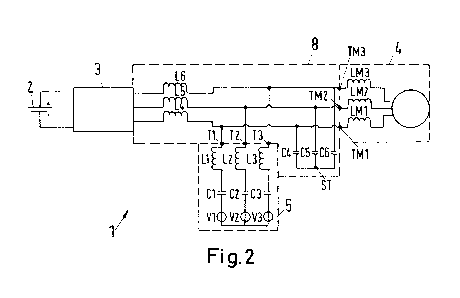
Fig. 2 shows a circuit diagram of a 3-phase electrical power supply system 1
according to
a first embodiment of the invention. Regarding the electrical elements such as
the traction
battery 2, the inverter 3, the electric machine 4 and the receiving device 5,
it can be
referred to the description of Fig. 1. With respect to the receiving device 5,
the series
connection of the capacitive elements 01, 02, 03 and the inductive elements
L1, L2, L3
are used for power factor correction or reactive power compensation. Also, the
receiving
CA 02876970 2014-12-16
WO 2014/006072 PCT/EP2013/063990
17
device 5 provides an alternating current output voltage with a constant
effective value or
RMS value.
In contrast to the electrical power supply system 1 shown in Fig. 1, the
electrical power
supply system 1 of Fig. 2 comprises a passive electric circuit arrangement 8.
The passive electric circuit arrangement 8 comprises circuit inductive
elements L4, L5, L6,
in particular one circuit inductive element L4, L5, L6 per phase. The circuit
inductive
elements L4, L5, L6 are electrically arranged between the output terminals T1,
T2, T3 of
the receiving device 5 and the inverter 3. Furthermore, the passive electric
circuit
arrangement 8 comprises circuit capacitive elements 04, 05, 06. One terminal
of the
circuit capacitive elements 04, 05, 06 is electrically connected to the output
terminals T1,
T2, T3 of the receiving device 5. The other terminals of the circuit
capacitive elements 04,
05, 06 are connected in a star point ST. One circuit capacitive element 04,
05, 06 is
assigned to each phase of the 3-phase-system. In particular, the circuit
capacitive
elements 04, 05, 06 are arranged in parallel to input terminals TM1, TM2, TM3
of the
electric machine 4. Motor inductive elements LM1, LM2, LM3 and the circuit
capacitive
elements 04, 05, 06 respectively provide a parallel resonant circuit.
With respect to the output terminals T1, T2, T3, a first transmission circuit
which is part of
the passive electric circuit arrangement 8 comprises the parallel resonant
circuit provided
by the circuit capacitive elements 04, 05, 06 and the motor inductive elements
LM1, LM2,
LM3. Again with respect to the output terminals T1, T2, T3, a second
transmission circuit
which is also part of the passive circuit arrangement 8 comprises the circuit
inductive
elements L4, L5, L6. A third transmission circuit, which is also part of the
passive electric
circuit arrangement 8, comprises the motor inductive elements L4, L5, L6 and
the
aforementioned parallel resonant circuit provided by the circuit capacitive
elements 04,
05, 06 and the motor inductive elements LM1, LM2, LM3.
According to the invention, the capacitances of the circuit capacitive
elements 04, 05, 06
and the inductances of the motor inductive elements LM1, LM2, LM3 are chosen
such that
at a charging frequency of 20 kHz the impedance provided by the first
transmission circuit
is higher than a first blocking impedance. Simultaneously, the inductances of
the circuit
inductive elements L4, L5, L6 are chosen such that at the charging frequency,
the
impedance provided by the second transmission is lower than a predetermined
second
CA 02876970 2014-12-16
WO 2014/006072 PCT/EP2013/063990
18
passing impedance. In addition, the inductances of the motor inductive
elements L4, L5,
L6, the capacitances of the circuit capacitive elements 04, 05, 06, and the
inductances of
the motor inductive elements LM1, LM2, LM3 are chosen such that at an
operating
frequency with a range from 0 kHz up to 10 kHz, an impedance provided by the
third
transmission circuit is lower than a third passing impedance. The inductances
of the circuit
inductive elements L4, L5, L6 have to be chosen such that an impedance of the
second
transmission circuit is higher than a second blocking impedance at the
operating
frequency. Also, the capacitances of the circuit capacitive elements 04, 05,
06 and the
inductances of the motor inductive elements LM1, LM2, LM3 have to be chosen
such that
an impedance of the first transmission circuit is higher than another first
blocking
impedance at the operating frequency.
The shown electrical power supply system 1 advantageously allows controlling
or
directing a energy flow or current flow between the inverter 2, the receiving
device 5, and
the electric machine 4 passively, e.g. without using additional active
elements such as
switches 7 (see Fig. 1) or power switches. The control of the energy flow or
current flow is
controlled by the design and the electrical elements of the passive electric
circuit
arrangement 8. In a motor mode, electric energy is transferred from the
traction battery 2
to the electric machine 4 via the inverter 3. The inverter 3 generates an
alternating current
output voltage with an operating frequency up to 10 kHz which can be a square
wave
voltage. Because of the series connection of the circuit inductive elements
L4, L5, L6 and
the motor inductive elements LM1, LM2, LM3 this square wave voltage and the
resulting
square wave currents are transformed to a nearly sinusoidal current. The
circuit inductive
elements L4, L5, L6 are also used to decouple the output voltage of the
inverter in the
operating mode, e.g. the square wave voltage, from the receiving device 5.
In the case of an inductive charging with the vehicle at a halt (static
charging), the electric
energy is transferred from the receiving device 5 to the inverter 3. The
receiving device 5
comprises the aforementioned inductive elements L1, L2, L3 and the capacitive
elements
01, 02, 03 which can be also referred to as compensation capacitors. These
electrical
elements and the circuit inductive elements L4, L5, L6 form a series resonant
circuit with a
predetermined transmission frequency. During static charging, a part of the
output voltage
of the receiving device 5 falls across the input terminals TM1, TM2, TM3 of
the electric
machine 4. The parallel resonant circuit formed by the circuit capacitive
elements 04, 05,
06 and the motor inductive elements LM1, LM2, LM3 provides a high impedance
for
CA 02876970 2014-12-16
WO 2014/006072 PCT/EP2013/063990
19
voltages within a frequency range of the charging frequency. Thus, there is no
or only a
minimal current flow to the electric machine 4.
lf, during operation of the vehicle in a motor mode, the electric energy is
transferred from
the inverter 3 to the electric machine 4, an electric current is free to flow
from the inverter
3 to the electric machine 4 as the parallel resonant circuit is not operated
at its resonant
frequency. Simultaneously, there is no or only minimal transfer of electric
energy from the
inverter 3 to the receiving device 5 because of the aforementioned series
resonant circuit.
Some frequencies of the output voltage of the inverter 3 operated in a motor
mode which
are in particular within a range of the resonant frequency of the series
resonant
connection can generate a resonant current in the receiving device 5. The
circuit inductive
elements L4, L5, L6 are minimizing this effect. During breaking of the
vehicle, e.g. during
recuperation, the vehicle can be operated in generator mode. The output
voltage
generated by the electric machine 4 in the generator mode is an sinusoidal
output voltage
and has a lower frequency than the resonant frequency of the receiving device
5. Thus,
there will be no or only a minimal current flow from the electric machine 4 to
the receiving
device 5. Simultaneously, however, an energy flow from the electric machine 4
to the
inverter 3 is undisturbed.
It is clear that a sufficient frequency spacing of the resonant frequency of
the respective
transmission circuits has to be provided for a correct functioning of the
proposed
invention.
In Fig. 3, an alternative embodiment of an electrical power supply system 1 is
shown.
Instead of the parallel resonant circuit comprising a circuit capacitive
element 04, 05, 06
(see Fig. 2) and motor inductive elements LM1, LM2, LM3, the passive electric
circuit
arrangement 8 comprises RC-parallel filters RC1, RC2, RC3, which are
electrically
arranged between output terminals T1, T2, T3 of the receiving device 5 and
input
terminals TM1, TM2, TM3 of the electric machine 4. Simultaneously, the RC-
parallel filters
RC1, RC2, RC3 are arranged between the inverter 3 and the electric machine 4
in series
to the circuit inductive elements L4, L5, L6. The RC-parallel filters RC1,
RC2, RC3 are a
part of the first transmission circuit and the third transmission circuit of
the passive electric
circuit arrangement 8. Each RC-parallel filter RC1, RC2, RC3 comprises a
capacitive
element and an inductive element which is connected in parallel to the
capacitive element.
CA 02876970 2014-12-16
WO 2014/006072 PCT/EP2013/063990
It is shown that the RC-parallel filters RC1, RC2, RC3 are exclusively part of
the passive
electric circuit arrangement 8 and not an element of the electric machine 4.
Also there is
one RC-parallel filter RC1, RC2, RC3 per phase of the 3-phase-system. The
proposed
design of the passive electric circuit arrangement 8 advantageously allows to
further
minimize the flow of electric current from the receiving device 5 to the
electric machine 4
during static charging while allowing the flow of electric current between the
inverter 3 and
the electric machine 4 during an operation mode, e.g. an operation in motor
mode or a
generator mode.