Note: Descriptions are shown in the official language in which they were submitted.
Photobioreactor for liquid cultures including sterilization mechanisms
Field
[0001] The present technology relates to a system for scale up and steady
state production
of liquid cultures under sterile conditions. More specifically, the technology
relates to a safe
bioreactor system for growing aquatic biological materials including salt
water zooplankton
and phytoplankton and combinations thereof.
Background
[0002] Bioreactors have been used for many years for cell culture, most
notably for
fermentation and more recently for the growth of bacteria. These cultures are
usually
contained in stainless steel vessels where gas exchange, temperature, pH,
dissolved oxygen
levels, and circulation are closely monitored and controlled.
[0003] Photobioreactors are reactors for material that requires light. There
are many
designs, ranging from open-air races, to tubes, to transparent vessels. The
vessels may have
banks of lights around the periphery or a central core of lights. The level of
control ranges
from essentially none, to strict monitoring of the growth conditions. Where
there is no
control over the growth conditions, sterility and maintenance of cell culture
purity are not
considered. This may be adequate for growth of algae for biofuel production,
but is not for
the growth of algae as a food source. In this instance, sensors and controls,
as disclosed in
US Publication No. 20110136225, are employed. A bioreactor module can be
connected to
one or more functional modules such as a pump module, a stimulation signal
generation
module, a motor module, a mechanical transmission module, a gas exchange
module, a
temperature module, a humidity module and/or a CO2 module, among others. The
bioreactor and functional modules can include standard or universal connectors
to facilitate
connection and movement of modules. The bioreactor system can be controlled
and/or
monitored by a controller that can individually identify and control each
connected module
and that can be adapted to collect signal data from sensors embedded in any of
the modules.
[0004] The use of sensors may require special adaptations. As disclosed in US
Publication No.
20110111489, a sensor adapter comprises an accommodating channel, in which the
sensor can be
positioned and the one end region of which is closed off by a semipermeable
membrane. Moreover,
the sensor adapter comprises a hollow cylindrical sealing structure, which is
disposed within the
1
CA 2877599 2017-08-29
CA 02877599 2019-12-22
WO 2014/006551 PCT/1B2013/055369
2
accommodating channel coaxially with the longitudinal axis of the latter and
with which the sensor can
be disposed gas tight adjacent to the semipermeable membrane.
[0005] Processors and programmes can be used to monitor outputs from sensors
and run the various
controllers. As disclosed in US Publication No. 20050208473, decision making
software can be used that
utilizes detected changes in the course of fermentation. Decisions are aimed
at determining the optima
for cellular growth, optimizing for production or degradation of metabolites
or substrates, or
determining the limits of growth under various combinations of conditions. The
invention determines
optima or limits in a manner more quickly and at less cost than traditional
methods. The basis for the
computer generated decisions may be first or second derivative changes
observed such as inflection
points, limits on allowable rates of change, or the like. The most common
measured parameter
controlling the decision making process is the optically observed growth of
the cells (e.g. microbial,
animal, or plant cell cultures) under study. Any other measurable parameter
(e.g. pH, temperature,
pigment production) may be used to control the process (i.e., the independent
variable). This process
and variations of this process on a laboratory scale are valuable for research
and development,
education, pilot plant models, and bio-manufacturing optimization, including
scale up to production
volumes.
Summary
[0006] The present technology is an integrated bioreactor comprising air,
carbon dioxide, nutrient,
sterilizant and neutralizer sources, lines from the sources to at least one
culture vessel, a culture line for
delivering seed culture to the vessel, a manifold to direct flow to and from
the culture vessel, lights,
sensors and a processor to control the functions of the bioreactor.
[0007] In one embodiment, the bioreactor has an integrated sterilization
system for in situ sterilization.
The technology allows for regular automated cleaning and sterilizing of a
bioreactor with minimal
interruption in production. Downtime can be less than 1 hour each week. From
one to a plurality of
culture vessels make up the bioreactor. The bioreactor provides controlled,
closed scale up.
[0008] Specifically, the bioreactor, which is for culturing cells in a liquid
environment, comprises:
-culture lines, culture medium lines, and a combined gas and sterilizant
manifold, the lines and manifold
comprising valves to control flow direction and flow rates, optionally,
pressure relief valves to relieve
pressure and optionally, pumps to maintain pressure;
CA 02877599 2019-12-22
WO 2014/006551 PCT/1B2013/055369
3
-a source of pressurized carbon dioxide, a source of pressurized air and a
sterilizant source each in
communication with the manifold;
-a culture medium source in liquid communication with the culture medium
lines;
-at least one vessel, the vessel comprising a side wall, a lid, a bottom,
sensors for reporting culture
conditions, a sparger, a sprayer, an inlet and an outlet;
-a transfer system for accepting a seed culture container, the transfer system
in communication with a
first vessel;
and
-a processor programmed to control culture conditions, execution of
sterilization schedules, and
incremental increases of volume of a culture on a schedule.
[0009] For use with phototrophic or nnixotrophic cultures, at least the side
wall is light transmitting and
the vessels are provided with lighting proximate the side wall.
[0010] The bioreactor may further comprise a base, wherein the side wall
comprises substantially
vertical contours and the base is contoured to mate with the side wall.
[0011] The vessels may further be provided with reflectors proximate the
lighting.
[0012] The bioreactor may further comprise at least one cleaner, the cleaner
comprising a blade, an
arm and a drive, the blade located within the at least one vessel and
magnetically coupled to the arm, or
directly driven, the arm configured to rotate around the vessel, and the drive
for driving rotation of the
arm, such that in use, the blade wipes the side walls within the vessel.
[0013] The sterilizant source may be a steam boiler or a liquid sterilizant
pack.
[0014] The processor may be programmed to increase culture volume on a cell
density based schedule.
[0015] The bioreactor may comprise at least two vessels, wherein the processor
is programmed to
transfer the culture from a first vessel to a second vessel to increase
culture volume.
[0016] The bioreactor may comprise one vessel, wherein the processor is
programmed to add culture
medium to the vessel to increase culture volume.
CA 02877599 2019-12-22
WO 2014/006551 PCT/1B2013/055369
4
[0017] In another embodiment, a bioreactor is provided, the bioreactor
comprising:
-culture lines, culture medium lines, and gas lines, the lines comprising
valves and optionally, pumps;
-gas sources in gaseous communication with the gas lines;
-a culture medium source in liquid communication with the culture medium
lines;
-at least one culture vessel comprising a side wall, a lid, a bottom, sensors
for reporting culture
conditions, a gas sparger in communication with the gas line, a culture medium
sprayer in
communication with the culture medium line, a culture inlet and a culture
outlet;
-a pressure driven transfer system for transferring a culture from a seed
culture container to the culture
vessel;
and
-a processor programmed to control culture conditions, incremental increases
in culture volume and
execution of sterilization cycles,
the improvement being an integrated sterilization system for in situ
sterilization of the bioreactor.
[0018] The integrated sterilization system may comprise the gas lines, a
sterilizant source in
communication with the gas lines, and sterilization cycle protocols programmed
in the processor.
[0019] The sterilizant source may be a steam boiler.
[0020] The sterilizant source may be a sterilizing fluid pack.
[0021] The bioreactor may further comprise a cleaner, the cleaner comprising a
blade, an arm and a
drive, the blade located within the vessel and coupled to the arm, the arm
configured to rotate and the
drive for driving rotation of the arm, such that in use, the blade wipes the
side walls within the vessel.
[0022] At least the side wall may be light transmitting, and the vessels may
be provided with lighting
proximate the side wall.
[0023] A bioreactor vessel is also provided, the vessel comprising a side
wall, a lid, a bottom, a base, the
base contoured to mate with the side wall, sensors for reporting culture
conditions, a gas sparger for
communication with a gas line, a culture medium sprayer for communication with
a culture medium
CA 02877599 2019-12-22
WO 2014/006551 PCT/1B2013/055369
line, a culture inlet and a culture outlet, wherein the side wall is light-
transmitting and comprises
substantially vertical contours of peaks and valleys.
[0024] The bioreactor vessel may further comprise a layer proximate the
lighting, the vertical contours
and layer defining air channels.
[0025] The bioreactor vessel may further comprise a combined stand and cooling
system, the
combined stand and cooling system comprising a framework of conduits and at
least one blower, the
blower in gaseous communication with a conduit inlet, the frame work of
conduits having a series of
outlets aligned with the air channels, such that in use, air is blown into a
lower end of the channels and
rises to the top of the channels thereby cooling the bioreactor vessel.
[0026] A processor-controlled method of promoting sterility in a bioreactor is
also provided, the
bioreactor comprising at least two culture vessels, sensors, culture lines,
culture medium lines, a
combined gas and sterilizant manifold, a sterilizant source, and inline
filters between the ambient
environment and the bioreactor, and a processor, the method comprising:
-the processor signaling a start of the sterilizing cycle;
-delivering sterilizant through the manifold to the bioreactor, at least
downstream of the inline filters;
and
-signaling an end of the sterilizing cycle, thereby promoting sterility in the
bioreactor.
[0027] The method may further comprise sensing contamination, and the
processor signaling emptying
of a culture vessels prior to signaling the start of the sterilization cycle.
[0028] The method may further comprise a cleaning step prior to signaling the
start of the sterilization
cycle.
[0029] A processor controlled method of culturing plant cells in a bioreactor
is also provided, the
bioreactor comprising a processor, a sterilizable transfer valve for accepting
a seed culture container, at
least one culture vessel with a culture line inlet and a culture line outlet,
sensors for the culture vessel,
lights, culture lines between the transfer valve and the at least one culture
vessel, culture medium lines,
a combined gas and sterilizant manifold, a sterilizant source, and inline
filters between the ambient
environment and the bioreactor, the method comprising:
CA 02877599 2019-12-22
WO 2014/006551 PCT/1B2013/055369
6
i) attaching the seed culture container to the transfer valve;
ii) the processor signaling a start of the sterilizing cycle, controlling
delivering sterilizant through the
manifold to the bioreactor, at least downstream of the inline filters, then
signaling a stop of the
sterilizing cycle;
iii) the processor signaling opening of the transfer valve and signaling
opening of the culture medium
lines, thereby controlling delivering culture medium and culture to a first
vessel;
iv) the sensors sending culture condition data to the processor, the processor
controlling culture
conditions; and
v) the processor terminating culturing and signaling emptying of the first
culture vessel.
[0030] The method may further comprise:
vi) the processor signaling cleaning of the at least one culture vessel.
[0031] The method may further comprise:
vii) the processor controlling transferring the emptied culture to at second
culture vessel and signaling
opening of the culture medium lines, thereby filling the second culture
vessel.
[0032] The method may further comprise:
viii) the processor signaling cleaning of the culture vessels.
[0033] In another embodiment, a bioreactor for culturing cells in a liquid
environment is provided, the
bioreactor comprising:
-culture lines, culture medium lines, and a combined gas and sterilizant
manifold, the lines and manifold
comprising valves to control flow direction and flow rates, optional pressure
release valves to relieve
pressure and optionally, pumps to maintain pressure;
-a culture vessel, the vessel comprising a transparent side wall, wherein the
side wall comprises
substantially vertical contours, a base, the base contoured to mate with the
side wall, a lid, sensors for
reporting culture conditions, a sparger, a sprayer, an inlet and an outlet;
-a light source disposed around the side wall;
CA 02877599 2019-12-22
WO 2014/006551 PCT/1B2013/055369
7
and
-a processor programmed to control culture conditions and execution of
sterilization schedules.
[0034] The side wall contours may be ridges and valleys, the peak to valley
height about 1/16th of an
inch to about 12 inches and the distance between the peaks about 1/16th of an
inch to about 12 inches.
[0035] The peak to valley height may be about 1 inch to about 6 inches and the
distance between the
peaks may be about 1 inch to about 6 inches.
[0036] The bioreactor may further comprise a cooling system, the cooling
system comprising at least
one fan and a distribution plate in communication with the at least one fan,
the distribution plate having
a network for directing air flow into each valley.
[0037] The bioreactor may further comprise a cooling plate or a cooling water
jacket disposed beneath
the distribution plate and for communication with a refrigeration
[0038] The bioreactor may further comprise a source of pressurized carbon
dioxide, a source of
pressurized air and a sterilizant source each in gaseous communication with
the manifold.
[0039] A processor-controlled method of promoting sterility in a bioreactor is
also provided, the
bioreactor comprising:
-culture lines, culture medium lines, and gas lines, the lines comprising
valves and optionally, pumps;
-gas sources in gaseous communication with the gas lines;
-a culture medium source in liquid communication with the culture medium
lines;
-at least one culture vessel comprising a side wall, a lid, a bottom, sensors
for reporting culture
conditions, a gas sparger in communication with the gas line, a culture medium
sprayer in
communication with the culture medium line, a culture inlet and a culture
outlet;
-a pressure driven transfer system for transferring a culture from a seed
culture container to the culture
vessel;
-a processor; and
-an integrated sterilization system for in situ sterilization of the
bioreactor,
CA 02877599 2019-12-22
WO 2014/006551 PCT/1B2013/055369
8
the method comprising:
-the processor signaling a start of the sterilizing cycle;
-delivering sterilizant through the integrated sterilization system of the
bioreactor, at least downstream
of the inline filters; and
- the processor signaling an end of the sterilizing cycle, thereby promoting
sterility in the bioreactor.
[0040] The method may further comprise the sensors reporting data to the
processor, the processor
determining contamination, and the processor signaling emptying of a culture
vessels prior to signaling
the start of the sterilization cycle.
[0041] The method may further comprise a cleaning step prior to signaling the
start of the sterilization
cycle.
[0042] A processor-controlled method of promoting sterility in a bioreactor is
also provided, the
bioreactor comprising:
-culture lines, culture medium lines, and a combined gas and sterilizant
manifold, the lines and manifold
comprising valves to control flow direction and flow rates, optional pressure
release valves to relieve
pressure and optionally, pumps to maintain pressure;
-a culture vessel, the vessel comprising a transparent side wall, wherein the
side wall comprises
substantially vertical contours, a base, the base contoured to mate with the
side wall, a lid, sensors for
reporting culture conditions, a sparger, a sprayer, an inlet and an outlet;
-a light source disposed around the side wall;
and
-a processor programmed to control culture conditions and execution of
sterilization schedules.
the method comprising:
-the processor signaling a start of the sterilizing cycle;
-delivering sterilizant through the combined gas and sterilizant manifold, at
least downstream of the
inline filters; and
CA 02877599 2019-12-22
WO 2014/006551 PCT/1B2013/055369
9
-signaling an end of the sterilizing cycle, thereby promoting sterility in the
bioreactor.
[0043] The method may further comprising the sensors reporting data to the
processor, the processor
determining contamination, and the processor signaling emptying of a culture
vessels prior to signaling
the start of the sterilization cycle.
[0044] The method may further comprise a cleaning step prior to signaling the
start of the sterilization
cycle.
[0045] A processor controlled method of culturing plant cells in a bioreactor
is also provided, the
bioreactor comprising:
-culture lines, culture medium lines, and gas lines, the lines comprising
valves and optionally, pumps;
-gas sources in gaseous communication with the gas lines;
-a culture medium source in liquid communication with the culture medium
lines;
-at least one culture vessel comprising a side wall, a lid, a bottom, sensors
for reporting culture
conditions, a gas sparger in communication with the gas line, a culture medium
sprayer in
communication with the culture medium line, a culture inlet and a culture
outlet;
-a pressure driven transfer system for transferring a culture from a seed
culture container to the culture
vessel;
-a processor programmed to control culture conditions, incremental increases
of culture volume and
execution of sterilization cycles; and
-an integrated sterilization system for in situ sterilization of the
bioreactor,
the method comprising:
i) attaching the seed culture container to a first culture line;
ii) the processor signaling pressurizing the seed culture container to deliver
culture to the culture vessel;
iii) the processor signaling opening of the culture medium lines, thereby
controlling delivering culture
medium to the culture vessel;
CA 02877599 2019-12-22
WO 2014/006551 PCT/1B2013/055369
iv) the sensors sending culture condition data to the processor, the processor
controlling culture
conditions and controlling incremental increases in culture volume in the
culture vessel; and
v) the processor terminating culturing and signaling emptying of the culture
vessel.
[0046] The method may further comprise:
vi) the processor signaling cleaning of the culture vessel.
[0047] The method may further comprise:
vii) the processor signaling execution of the sterilization cycle.
[0048] In another embodiment a bioreactor for culturing cells in a liquid
environment is provided, the
bioreactor comprising:
-culture lines, culture medium lines, and a combined gas and culture manifold,
the lines and manifold
comprising valves to control flow direction and flow rates, pressure relief
valves to relieve pressure and
pumps to maintain pressure;
-a source of pressurized carbon dioxide and a source of pressurized air in
communication with the
manifold;
-a culture medium source in liquid communication with the culture medium
lines;
-at least one vessel, the vessel comprising a side wall, a lid, a bottom,
sensors for reporting culture
conditions, a sparger, at least one inlet and an outlet;
- a sterilizant source in communication with the vessel;
-a transfer system for accepting a seed culture container, the transfer system
in communication with a
first vessel;
and
-a processor programmed to control culture conditions, execution of
sterilization schedules, and
incremental increases of volume of a culture on a schedule.
[0049] For phototrophic or mixotrophic cultures, at least the side wall may be
light transmitting and the
vessels may be provided with lighting proximate the side wall.
CA 02877599 2019-12-22
WO 2014/006551 PCT/1B2013/055369
11
[0050] The bioreactor may further comprise a base, wherein the side wall
comprises substantially
vertical contours and the base is contoured to mate with the side wall.
[0051] The vessels may be further provided with reflectors proximate the
lighting.
[0052] The bioreactor may further comprise at least one cleaner, the cleaner
comprising a blade, an
arm and a drive, the blade located within the at least one vessel and
magnetically coupled to the arm, or
directly driven, the arm configured to rotate around the vessel, and the drive
for driving rotation of the
arm, such that in use, the blade wipes the side walls within the vessel.
[0053] The sterilizant source may be a steam boiler or a liquid sterilizant
pack.
[0054] The processor may be programmed to increase culture volume on a cell
density based schedule.
[0055] The bioreactor may comprise at least two vessels, wherein the processor
is programmed to
transfer the culture from a first vessel to a second vessel to increase
culture volume.
[0056] The bioreactor may comprise one vessel, wherein the processor is
programmed to add culture
medium to the vessel to increase culture volume.
[0057] The bioreactor may further comprise a heat exchanger or water jacket
for cooling the culture
vessel.
Figures
[0058] Figure 1 is a plan view of the bioreactor of the present technology.
[0059] Figure 2 is a schematic of the bioreactor of Figure 1.
[0060] Figure 3 is a longitudinal sectional view of the scale up vessel of the
present technology.
[0061] Figure 4 is a longitudinal sectional view of the feed vessel of the
present technology.
[0062] Figure 5A and 58 are longitudinal sectionals view of the cleaner and
the alternative cleaner.
[0063] Figure 6 is a schematic of a second embodiment.
[0064] Figure 7 is a longitudinal sectional view of the feed culture vessel of
the bioreactor of Figure 6.
[0065] Figure 8 shows the side wall of the feed culture vessel of Figure 7.
CA 02877599 2019-12-22
WO 2014/006551 PCT/1B2013/055369
12
[0066] Figure 9 is a schematic of the third embodiment of a bioreactor.
[0067] Figure 10 is a schematic of the fourth embodiment of a bioreactor.
Description
[0068] Except as otherwise expressly provided, the following rules of
interpretation apply to this
specification (written description, claims and drawings): (a) all words used
herein shall be construed to
be of such gender or number (singular or plural) as the circumstances require;
(b) the singular terms "a",
"an", and "the", as used in the specification and the appended claims include
plural references unless
the context clearly dictates otherwise; (c) the antecedent term "about"
applied to a recited range or
value denotes an approximation within the deviation in the range or value
known or expected in the art
from the measurements method; (d) the words "herein", "hereby", "hereof",
"hereto", "hereinbefore",
and "hereinafter", and words of similar import, refer to this specification in
its entirety and not to any
particular paragraph, claim or other subdivision, unless otherwise specified;
(e) descriptive headings are
for convenience only and shall not control or affect the meaning or
construction of any part of the
specification; and (f) "or" and "any" are not exclusive and "include" and
"including" are not limiting.
Further, The terms "comprising," "having," "including," and "containing" are
to be construed as open-
ended terms (i.e., meaning "including, but not limited to,") unless otherwise
noted.
[0069] To the extent necessary to provide descriptive support, the subject
matter and/or text of the
appended claims is incorporated herein by reference in their entirety.
[0070] Recitation of ranges of values herein are merely intended to serve as a
shorthand method of
referring individually to each separate value falling within the range, unless
otherwise indicated herein,
and each separate value is incorporated into the specification as if it were
individually recited herein.
Where a specific range of values is provided, it is understood that each
intervening value, to the tenth of
the unit of the lower limit unless the context clearly dictates otherwise,
between the upper and lower
limit of that range and any other stated or intervening value in that stated
range, is included therein. All
smaller sub ranges are also included. The upper and lower limits of these
smaller ranges are also
included therein, subject to any specifically excluded limit in the stated
range.
[0071] Unless defined otherwise, all technical and scientific terms used
herein have the same meaning
as commonly understood by one of ordinary skill in the relevant art. Although
any methods and
CA 02877599 2019-12-22
WO 2014/006551 PCT/1B2013/055369
13
materials similar or equivalent to those described herein can also be used,
the acceptable methods and
materials are now described.
Definitions:
[0072] Aquatic ¨ in the context of the present technology, aquaculture
includes the culturing of
biological material in fresh water, salt water, brackish water, brine and the
like ¨ essentially any liquid.
[0073] Culture ¨ in the context of the present technology, culture, as in
culture line or culture vessel,
refers to a combination of biological material, culture medium and any
additional chemicals produced
by the biological material during the culturing process. Cultures require
appropriate sources of food and
energy, provided by the culture medium, and a suitable physical environment.
Tissue cultures can
themselves become a culture medium for viruses, which grow only with live
cells. Cultures of only one
kind of cells are known as pure cultures, as distinguished from mixed or
contaminated cultures.
[0074] Cell ¨ in the context of the present technology, cell means any cell or
cells, as well as viruses or
any other particles having a microscopic size, e.g. a size that is similar to
that of a biological cell, and
includes any prokaryotic or eukaryotic cell, for example, but not limited to
bacteria, fungi, plant and
animal cells. A cell may be living or dead. As used herein, a cell is
generally living unless otherwise
indicated. Cells may be a plurality of individual cells or may be cell clumps,
aggregates or groupings.
The cells may be undifferentiated or differentiated, but are not formed into
tissues.
[0075] Tissue ¨ in the context of the present technology, tissue means an
aggregation of cells more or
less similar morphologically and functionally.
[0076] Sensor¨ in the context of the present technology, sensor is defined as
any device that can
measure a measurable quantity. For examples, a sensor can be, but is not
limited to a thermal detector,
an electrical detector, a chemical detector, an optical detector, an ion
detector, a biological detector, an
electrochemical detector, a magnetic detector, a capacitive detector, a
pressure detector, an ultrasonic
detector, an infrared detector, a microwave motion detector, an electric eye,
and an image sensor.
[0077] Culture medium ¨ in the context of the present technology, culture
medium refers to a liquid
comprising chemicals needed to support growth and maintenance of cells. The
chemicals may be
nutrients, including but not limited to vitamins, minerals, micronutrients,
amino acids. The chemicals
may also comprise osmoticunn, a carbon source, biological extracts, and
buffers. A medium can be
provided with one or more analytes to be consumed by one or more cells. In
some instances, culture
CA 02877599 2019-12-22
WO 2014/006551 PCT/1B2013/055369
14
medium may simply be salt water, wherein salt water is defined as ocean water
or brine pond water, or
it may be brackish water.
[0078] Plant ¨ in the context of the present technology, plant refers to any
organism, cell or cells that
photosynthesize.
Apparatus:
[0079] Itemized list of the main components:
1. Sterilizant system;
2. Water treatment system;
3. Clean-in-place system (CIP);
4. Air and CO2 addition;
5. Control system - Programmable Logic Controller (PLC) Based;
6. Seed culture container;
7. Scale up vessel;
8. Feed vessel; and
9. Cooling system (as described in "Second embodiment")
[0080] A bioreactor, generally referred to as 10, is shown in Figure 1. A seed
culture container 12
connects via a first culture line 14 to a scale up vessel 200, which in turn
connects via a second culture
line 18 to a feed vessel 300. The seed culture container 12 is transiently
attached to the first culture line
14 via a sterilizable transfer valve 22, or alternatively, is directly
attached to the scale up vessel 200 via
the transfer valve 22, again transiently. There is an incremental volume
increase in the vessels from the
seed culture container 12 to the scale up vessel 200 to the feed vessel 300.
Each vessel has a second
bottom 16 to define a water chamber for cooling the vessels 200, 300. This
functions as a heat
exchanger.
[0081] Figure 2 is a schematic of the bioreactor 10. A steam generator 24 is
used for sterilizing the
bioreactor 10. An air source 26, which may be a tank or ambient air and a
pressurized CO2 tank 28 are
CA 02877599 2019-12-22
WO 2014/006551 PCT/1B2013/055369
connected via gas lines 30 to the injectors 32 located in the interior 201 of
the scale up vessel 200 and
the interior 301 of the feeder vessel 300. A processor 34 controls delivery of
air and CO2 as needed. A
regulator and digital pressure gauge 36 is located downstream from the CO2
tank 28 on the CO2 line 38
portion of the gas line 30. A valve 31 is located downstream. Three way, 2
position solenoid valves 40
communicate with the processor 34 and are located on the gas lines 30. An air
pump 42 is on the air
line 44 portion of the gas line 30 and is calibrated to produce a pressure
between about 2 psi to about
15 psi. A check valve 46 is located between the air pump 42 and one of the
three way, two position
solenoid valves 40. A 0.34.inn steam-in-place filter 48 is located upstream
from the solenoid valve 40.
The solenoid valve 40 splits the air line 44 into an air dump line 50 and the
air line 44. The CO2 line 38
and the air line 44 connect at three way solenoid valves 40 to form the gas
lines 30. The CO2 line 38, the
air line 44, and the gas lines 30 form a manifold. This manifold also
distributes steam or more generally,
sterilizant, allowing for easy steam sterilization of the lines.
[0082] The first culture line 14 enters the scale up vessel 200 at an inlet
203. Downstream from the
transfer valve 22, the first culture line 14 has a three way valve 430 that
can be manually operated and a
two way valve 432 in line. The first culture line 14 optionally has an inline
pump to pressurize the
transfer mechanism.
[0083] The second culture line 18 leaves the scale up vessel through an outlet
70. A first dump line
splits 72 from the second culture line 18. Both have two way valves ¨ 74 on
the dump line and 76 on the
second culture line 18. The second culture line 18 enters the feed vessel 300
at an inlet 301.
[0084] A third culture line 80 leaves the feed vessel 300 through an outlet
82. The third culture line 80
passes through an inline pump 84, which is preferably a peristaltic pump or a
shuttle pump, but may be
a rotary pump, and a second dump line 86 splits off. Both have two way valves
¨88 on the dump line 86
and 90 on the third culture line 80. Additionally, the third culture line 80
has a one way check valve 92
downstream. An outlet 94 terminates the third culture line 80. At this point
the feed culture is supplied
to the customer either as is, or in a concentrated form, by including a
concentrator 96 either upstream
or downstream from the outlet 94. The concentrator 96 may be any suitable
concentrator, for example,
but not limited to a centrifuge or a filtration system.
[0085] A water line 390 for sea water has an inline 100 Linn filter 392, is
joined by two nutrient lines 394
from nutrient packs 396 to become a culture medium line 398 and then passes an
ultravoilet (UV) light
source 399 located downstream. The culture medium line 398 enters a booster
tank 400 that is
CA 02877599 2019-12-22
WO 2014/006551 PCT/1B2013/055369
16
supplied with a heater 402 and a pressure sensor 404. The line 398 leaves the
tank 400 through an
outlet 406, passes through an inline pump 408, which is preferably a
peristaltic pump or shuttle pump,
but may be a rotary pump, and a one way check valve 410 to a three way
diverter valve 412 that directs
flow to the scale up vessel 200 or the feed vessel 300. A first sprayer 414
sprays the contents of the line
into the scale up vessel 200. A second sprayer 416 sprays the contents of the
line into the feed vessel
300. The sprayers 414 and 416 are preferably rotary spray nozzles. The
processor 34 controls the one
way check valve 410 and the three way diverter valve 412, which are solenoid
valves, to control flow.
[0086] A fresh water supply 430 passes through a 50 p.m filter 432 and enters
a steam generator, for
example, a boiler 434. A first steam line 436 from the steam generator 434
enters the CO2 line 38 and
the air line 44 at the solenoid valves 40. A second steam line 438 enters the
water line downstream from
the nutrient lines 394 and upstream from the UV light source 399. A third
steam line 440 delivers steam
to the transfer valve 22. The steam lines, manifold and overall integration of
the bioreactor allow for in
situ sterilization of either the entire bioreactor, or select vessels and
lines.
[0087] The scale up vessel, generally referred to as 200 is shown in Figure 3.
The scale up vessel is
about 200 to about 2,000 litres, or about 500 to about 1500 litres or 1,000
litres and all ranges
therebetween. If algae or other plant material is to be cultured, at least the
side walls 202 are
transparent or light transmitting. The lip 203 of the wall 202 is formed into
a flange 204 and has
openings 206 to accept bolts 208 for affixing an airtight lid 210. As the
vessel is steam-cleaned, both the
vessel 200 and the lid 210 are made of steam-resistant material, for example,
but not limited to
fiberglass or a heat resistant polyethylene such as Tyvar . The lid 210 has an
access port 212 for
accepting a clean in place system(CIP), generally referred to as 214. Gaskets
216 are located between
the lid 210 and flange 204 and between a CIP flange 218 of the CIP 414 and the
lid 210.
[0088] The scale up vessel 200 is equipped with a bottom access 230 on or in
the vicinity of the bottom
231 connected to the gas lines 30 and the outlet 70 connected to the second
culture line 18. The gas
line 30 terminates in a sparger 232. The first culture line 14 enters into the
scale up vessel 200 on a side
wall 202. An optional thin plastic polymer shell 234 surrounds the side wall
202 and is equipped with
light emitting diode grow lights 236. An optional reflective surface 238 is
located on an outer side of the
shell 234. Lights 205 may additionally be provided on the lid 210. As shown in
Figure 2, the scale up
vessel 200 is provided with sensors for reporting culture conditions, for
example, but not limited to each
of a pH 240, optical density 242, temperature 244, and pressure sensor 246.
Capacitance sensors 248
CA 02877599 2019-12-22
WO 2014/006551 PCT/1B2013/055369
17
are located at a number of depths, for example, two located at 1/3 and 2/3
depth, three located at 1/4, 1/4,
'A depth or four located at 1/5, 2/5, 3/5 and 4/5 depth.
[0089] The feed culture vessel, generally referred to as 300, is shown in
Figure 4. The feed culture
vessel is about 100 to about 100,000 litres, or about 250 to about 75,000
litres or 50,000 litres and all
ranges therebetween. If algae or other plant material is to be cultured, at
least the side walls 302 are
transparent or light transmitting. The lip of the wall 303 is formed into a
flange 304 and has openings
306 to accept bolts 308 for affixing an airtight lid 310. As the vessel is
steam-cleaned, both the vessel
300 and the lid 310 are made of steam-resistant material, for example, but not
limited to fiberglass or a
heat resistant polyethylene such as Tyvar . The lid 310 has an access port 312
for accepting a clean in
place systenn(CIP), generally referred to as 416. Gaskets 316 are located
between the lid 310 and flange
304 and between a CIP flange 318 and the lid 310.
[0090] The feed culture vessel 300 is equipped with a bottom access 330 on or
in the vicinity of the
bottom 331 connected to the gas lines 30 and an outlet 82 connected to the
third culture line 80. The
gas line 30 terminates in a sparger 332. The second culture line 18 enters the
feed culture vessel 300 at
a side wall 302. An optional thin plastic polymer shell 334 surrounds the
vessel 300 and is equipped
with light emitting diode grow lights 336. An optional reflective surface 338
is located on an outer side
of the shell 334. Lights 305 may additionally be provided on the lid 310. As
shown in Figure 2, the feed
culture vessel 300 is provided with sensors for reporting culture conditions,
for example, but not limited
to each of a pH 340, optical density 342, temperature 344, and pressure sensor
346. Capacitance
sensors 348 are located at a number of depths, for example, two located at 1/3
and 2/3 depth, three
located at 1/4, 1/4, %depth or four located at 1/5, 2/5, 3/5 and 4/5 depth.
[0091] The bioreactor is controlled by the processor 34. It receives and
process data from the various
sensors (pH, optical density, temperature, pressure), and coordinates the
activity of the solenoids,
pumps, steam cleaning, lighting and heating. If desired, the processor 34 can
be made to interface
wirelessly to a computer to allow remote monitoring and control.
[0092] As shown in Figure 5A, a cleaner, generally referred to as 100 is for
placing in the scale up and
feed culture vessels 200, 300. A blade 102 for locating inside the culture
vessels 200, 300 is
magnetically coupled to a rotating arm 104 which is configured to move around
the outside of the
vessels 200, 300. As would be known to one skilled in the art, the magnet 106
and the magnetic
material 108 can be interchangeably located on the rotating arm 104 and the
blade 102. Alternatively,
CA 02877599 2019-12-22
WO 2014/006551 PCT/1B2013/055369
18
the blade 102 may be directly driven. The cleaner 100 is preferably contoured
to the inner surface 110
of the vessel 200, 300, or can be flexible, for example, but not limited to
iron filings encased in a long
flexible plastic covering or brushes located on the blade 102. In an
alternative embodiment, as shown in
Figure 5B, small free floating parts 112 are placed inside the culture vessels
200, 300. These free
floating parts 112 are carried by gas currents 114 in the culture medium 116
and keep the inner surface
110 clean through continuous small impacts.
Method:
[0093] The design of the bioreactor provides for a minimum downtime and
maximum efficiency. As
each vessel is emptied, both the vessel and the lines leading to it can be
sterilized. Additionally, the
entire bioreactor can be cleaned and sterilized. Once scale up has begun, the
system is closed and
remains closed until harvest, which is preferably in late log phase, but may
be earlier or later. In this
closed system (i.e. one that does not require open transfers), the volume of
the vessels increases
incrementally from the seed vessel to the scale up vessel to the feed vessel,
on a schedule and under
control of the processor, hence contamination can be contained to a relatively
small volume, as
compared to having one large culture vessel filled with culture medium. Also,
the level of security
increases as the number of valves, lines and vessels from the ambient
environment increase, hence the
larger the vessel, the further it is removed from ambient and therefore the
less chance there is of
contamination. Culture medium used for cleaning the vessels may be dumped or
retained to scale up
the culture volume. Should contamination occur in any one vessel the processor
will detect the
contamination, based on data from at least one sensor and will control
emptying of the vessel. The
vessel may additionally be cleaned, by the processor signaling a cleaning step
before the sterilizing cycle
begins. Gaseous sterilizant is fed through the bioreactor by means of the
steam lines and manifold. All
transfers are automated, thereby reducing the risk of contamination.
Second embodiment:
[0094] Itemized list of the main components:
1. Sterilizant system;
2. Water treatment system;
3. Clean-in-place system (CIF);
CA 02877599 2019-12-22
WO 2014/006551 PCT/1B2013/055369
19
4. Air and CO2 addition;
5. Control system - Programmable Logic Controller (PLC) Based;
6. Seed culture container;
7. Feed culture vessel; and
8. Cooling system.
[0095] Figure 7 is a schematic of a second embodiment of a bioreactor 510. The
seed culture container
512 connects via the first culture line 514 to a feed vessel 600. The seed
culture container 512 is
transiently attached to the first culture line 514, which directly feeds the
feed vessel 600. The first
culture line 514 enters the feed vessel 600 at an inlet 603. The first culture
line 514 has a two way valve
48 in line.
[0096] The air line 516 and the first culture line 514 enter the seed culture
container 512 through a
bung 518. The air line 516 is connected to a pump 520 for pumping air into the
carboy 512, thereby
increasing the pressure, and forcing culture through the first culture line
514. The air line 516, first
culture line 514, bung 518 and pump 520 are collectively referred to as the
pressure driven transfer
system. A steam generator 24 is used for sterilizing the bioreactor 510. An
air source 26, which may be
a tank or ambient air and a pressurized CO2 tank 28 are attached via gas lines
30 to the injectors 32
located in the interior 601 of the feed vessel 600. A processor 34 controls
delivery of air and CO2 as
needed. A regulator and digital pressure gauge 36 is located downstream from
the CO2 tank 28 on the
CO2 line 38 portion of the gas line 30. A valve 31 is located downstream. A
three way, 2 position
solenoid valve 40 communicates with the processor 34 and is located on the gas
lines 30. An air pump
42 is on the air line 44 portion of the gas line 30 and is calibrated to
produce a pressure of about 2 psi to
about 15 psi. Check valves 46 are located on the air line 44 both on the air
intake line and the air pump
line. A 0.1p.nn steam-in-place filter 48 is located upstream from the solenoid
valve 40. It splits the air line
44 into an air dump line 50 and the air line 44. The CO2 line 38 and the air
line 44 connect at three way
solenoid valves 40 to form the gas lines 30. The CO2 line 38, the air line 44,
and the gas lines 30 form a
manifold. This manifold also distributes steam or more generally, sterilizant,
allowing for easy steam
sterilization of the lines.
[0097] A water line 390 for sea water has an inline 100 p.m filter 392, and a
valve 393. It is joined by
two nutrient lines 394 from nutrient packs 396 to become a culture medium line
398. Each nutrient line
CA 02877599 2019-12-22
WO 2014/006551 PCT/1B2013/055369
394 is equipped with a pump 408, which is preferably a peristaltic pump or
shuttle pump, but may be a
rotary pump and a check valve 410. The nutrient lines 394 upstream from the
peristaltic pump 408 are
preferably disposable. The culture medium line 398 passes through an inline
pump 408, which is
preferably a peristaltic pump or shuttle pump, but may be a rotary pump. A
sprayer 416 sprays the
contents of the line into the feed vessel 600. The sprayer 416 is preferably a
rotary spray nozzle. This is
the CIP. The feed vessel 600 has a pressure relief line 700 with a pressure
relief valve 702 and an
atmosphere dump 704.
[0098] A fresh water supply 430 passes through a 50 p.m filter 432 and enters
a steam generator, for
example, a boiler 434. A first steam line 436 from the steam generator 434
enters the air line 44
between the filter 48 and the solenoid valves 40. A second steam line 438
enters the water line
upstream from the nutrient lines 394. The steam lines, manifold and overall
integration of the
bioreactor allow for in situ sterilization of either the entire bioreactor, or
select vessels and lines. The
steam lines 436, 438 have a pressure release valve 439.
[0099] A third culture line 80 leaves the feed culture vessel 600 through an
outlet 82. The third culture
line 80 passes through an inline pump 84, which is preferably a peristaltic
pump or a shuttle pump, but
may be a rotary pump, and a second dump line 86 splits off. Both have two way
valves ¨ 88 on the
dump line 86 and 90 on the third culture line 80. Additionally, the third
culture line 80 has a one way
check valve 92 downstream. An outlet 94 terminates the third culture line 80.
At this point the feed
culture is supplied to the customer either as is, or in a concentrated form,
by including a concentrator 96
either upstream or downstream from the outlet 94. The concentrator 96 may be
any suitable
concentrator, for example, but not limited to a centrifuge or a filtration
system.
[00100]The feed culture vessel, generally referred to as 600, is shown in
Figure 7. The feed culture
vessel is about 100 to about 100,000 litres, or about 250 to about 75,000
litres or 50,000 litres and all
ranges therebetween. If algae or other plant material is to be cultured, at
least the side walls 602 are
transparent or light transmitting. The side wall 602 is preferably
polycarbonate. The lip 603 of the wall
602 is formed into a flange 604 and has openings 606 to accept bolts 608 for
affixing an airtight lid 610.
As the vessel is steam-cleaned, both the vessel 600 and the lid 610 are made
of steam-resistant
material, for example, but not limited to fiberglass or a heat resistant
polyethylene such as Tyvar . The
lid 610 has an access port 612 for accepting a clean in place system (CIP),
generally referred to as 416.
Gaskets 616 are located between the lid 610 and flange 604 and between a CIP
flange 618 and the lid
610.
[00101] The feed culture vessel 600 is equipped with a bottom access 630 on or
in the vicinity of
the bottom 631 connected to the gas lines 30 and an outlet 82 connected to the
third culture line
80. The gas line 30 terminates in a sparger 632. The first culture line 514
enters the feed vessel
600 at an inlet 603. An optional thin plastic polymer shell 634 surrounds the
vessel 600 and is
equipped with vertically disposed light emitting diode grow lights 636
proximate the outer surface.
Lights 605 may additionally be provided on the lid 610. An optional reflective
surface 638 is located
on an outer side of the shell 634. As shown in Figure 6, the feed culture
vessel 600 is provided with
sensors for reporting culture conditions, for example, but not limited to each
of a pH 640, optical
density 642, temperature 644, and pressure sensor 646. Capacitance sensors 648
are located at
a number of depths, for example, two located at 1/3 and 2/3 depth, three
located at 'A, 1/2, % depth
or four located at 1/5, 2/5, 3/5 and 4/5 depth.
[00102] As shown in Figure 8, the side wall 602 is formed into vertically
disposed ridges 650 and
valleys 652. They may be rounded or sharp edged and may be wavy 651 about
their vertical axis
653. The vertical contours 654 may be, but are not limited to waves, or ridges
and valleys, or peaks
and troughs or are accordion-shaped, and are substantially vertical, for
example, the vertical axis
is normal to the floor, about 85 degrees relative to the floor, about 80
degrees relative to the floor
or about 75 degrees relative to the floor. The vertical contours 654 function
to increase the surface
area of the side wall 602 and thereby increase light penetration in the feed
culture vessel 600. The
peak to valley height of the contours 654 is about 1/16 of an inch to about 1
foot, or about 1 inch
to about 6 inches or about 3 inches and all ranges therebetween. The distance
between the peaks
is about 1/16 of an inch to about 1 foot, or about 1 inch to about 6 inches,
or 3 inches and all ranges
therebetween. Additionally, the contours 654 preferably have small
corrugations 655 to further
increase the surface area. A bottom plate 656 retains the side wall 602 and
has plate contours 658
that correspond to the contours 654 of the side wall 602. Alternatively, the
bottom plate 656 may
have a contoured groove 660 (shown in Figure 8, inset) to accept the side wall
602.
[00103] A cooling system provides air flow to the space between the feed
culture vessel 600 and
light emitting diode grow lights 636 (See Figure 8). This space is referred to
as the air channel 662.
As shown in Figure 7, blowers or fans 664 force air down through the air
channel 662, which then
exits from the bottom 672 of the air channel 662. Similarly, blowers or fans
force air down through
the air channels in the vessels of Figure 3 and Figure 4.
[00104] The bioreactor is controlled by the processor 34. It receives and
process data from the various
sensors (pH, optical density, temperature, pressure), and coordinates the
activity of the solenoids,
21
CA 2877599 2017-08-29
CA 02877599 2019-12-22
WO 2014/006551 PCT/1B2013/055369
22
pumps, steam cleaning, lighting and heating. If desired, the processor 34 can
be made to interface
wirelessly to a computer to allow remote monitoring and control.
[00105]The cleaner and alternative cleaner are shown in Figures 5 and 6.
Method:
[00106] The design of the bioreactor provides for a minimum downtime and
maximum efficiency. As the
vessel is emptied, both the vessel and the lines leading to it can be
sterilized. Additionally, the entire
bioreactor can be cleaned and sterilized. Once scale up has begun, the system
is closed and remains
closed until harvest, which is preferably in late log phase, but may be
earlier or later. Initially, the feed
culture vessel contains a small amount of culture medium. In this closed
system (i.e. one that does not
require open transfers), the volume of culture medium increases incrementally
on a schedule, under
control of the processor, hence contamination has a smaller chance of
establishing itself. Since less
medium (a vector for contamination) is added at the beginning of the scale up,
there is a smaller chance
that contaminant organisms are added early on. This limits the amount of time
that contaminants are
multiplying in the system, and increases competition for resources, which on
average will produce
significantly less contaminated cultures. Culture medium used for cleaning the
vessels may be dumped
or retained to scale up the culture volume. Should contamination occur in the
vessel the processor will
detect the contamination, based on data from at least one sensor and will
control emptying of the
vessel. The vessel may additionally be cleaned by the processor signaling a
cleaning step before the
sterilizing cycle begins. Gaseous sterilizant is fed through the bioreactor by
means of the steam lines
and manifold.
[00107] Third embodiment
Itemized list of the main components:
1. Sterilizant system;
2. Water treatment system;
3. Clean-in-place system (CIP);
4. Air and CO2 addition;
5. Control system - Programmable Logic Controller (PLC) Based;
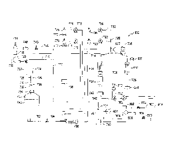
CA 02877599 2019-12-22
WO 2014/006551 PCT/1B2013/055369
23
6. Seed culture container;
7. Culture vessel; and
8. Cooling system.
[00108] A schematic of a third embodiment, generally referred to as 700 is
shown in Figure 9. The seed
culture container 702 connects via the first culture line 704 to the culture
vessel 706. The seed culture
container 702 is transiently attached to a first culture line 704, which
directly feeds the culture vessel
706. The first culture line 704 enters the culture vessel 706 at an inlet 714.
[00109] A first air line 710 has an air source 716 which may be a tank or
ambient air. A pump 718 forces
the air to a T-junction 720, to a second air line 722 that branches from the
first air line 710 at the T-
junction 720. The pump 718 is calibrated to produce a pressure of about 2 psi
to about 15 psi. The
second air line 722 has a two way manual valve 724 and a fitting 726
downstream from the valve 724 for
a user to attach a third air line 730 with an air filter 732. The third air
line 730 enters the seed culture
container 702 through a bung 734. The first culture line 704 similarly has a
fitting 736 for attaching a
second culture line 738 that enters the seed culture container 702 through the
bung 734. When the
valve 724 is open and the air lines 706, 722, 730 are pressurized by the pump
718, culture 740 is forced
from the seed culture container 702 to the first culture line 704 that leads
to the culture vessel 706. The
air lines 706, 722, 730, culture line 704, 738 and pump 718 are collectively
referred to as the pressure
driven transfer system. Alternatively, the transfer valve 22 described above
could be employed.
[00110] A pressurized CO2 tank 744 provides CO2 to a CO2 line 746. A regulator
and digital pressure
gauge 748 is located downstream from the CO2 tank 744 on the CO2 line 746 and
a three way two
position solenoid valve 749 is located downstream from the regulator and
digital pressure gauge 748.
The CO2 line 746 joins the first air line 710 to form a gas line 750, which
delivers to the culture vessel
706 through injectors or spargers 752 located in the interior 754 of the
culture vessel 706. Upstream
from the gas line 750, a three way, two position solenoid valve 756 is located
on the first air line 710. A
processor 758 controls delivery of air and CO2 as needed by communicating with
the valves 746, 756. A
0.11.trn filter 760 is located on the gas line 750.
[00111] A water line 762 for sea water has a two position solenoid valve 764
and optionally, an inline
ultraviolet filter. The water line 762 and the gas line 750 connect to form a
common line 766
downstream of the valve 764. A two position solenoid valve 768 is downstream
from the connection
CA 02877599 2019-12-22
WO 2014/006551 PCT/1B2013/055369
24
770. The common line 766 enters the culture vessel 706 at a sprayer 772 that
sprays the contents of the
common line 766 (which is normally primarily liquid, but, by closing the valve
726 on the water line 762,
can become a gas line) into the culture vessel 706. The sprayer 772 is
preferably a rotary spray nozzle.
[00112]Two nutrient lines 774 from nutrient packs 776 are each equipped with a
pump 778, which is
preferably a peristaltic pump or shuttle pump, but may be a rotary pump. The
nutrient lines 774
upstream from the peristaltic pump 778 are preferably disposable. The nutrient
lines 774 enter the
culture vessel 706 at an upper end 780.
[00113] A sterilizant line 782 from a sterilizer pack 784 is equipped with a
pump 786, which is preferably
a peristaltic pump or shuttle pump, but may be a rotary pump. Similarly, a
neutralizer or detoxifier line
788 from a neutralizer or detoxifier pack 790 is equipped with a pump 792. The
lines 782, 788 enter the
culture vessel 706 at an upper end 794. The gas line 750, common line 766 and
sterilizant line 782 form
a manifold to provide an integrated sterilization system for in situ
sterilization.
[00114]A 2-directional air filter 795 extends from the culture vessel 706 at
an upper end 794 and
functions as a pressure release valve. A third culture line 800 leaves the
culture vessel 706 through an
outlet 802. The third culture line 800 passes through an inline pump 804,
which is preferably a
peristaltic pump or a shuttle pump, but may be a rotary pump, and a dump line
806 splits off. Both have
two way valves ¨ 808 on the dump line 806 and 810 on the third culture line
800. Additionally, the third
culture line 800 has a one way check valve 812 downstream. An outlet 814
terminates the third culture
line 800. At this point the feed culture is supplied to the customer either as
is, or in a concentrated
form, by including a concentrator 816 either upstream or downstream from the
outlet 802. The
concentrator 816 may be any suitable concentrator, for example, but not
limited to a centrifuge or a
filtration system.
[00115] A liquid sterilizer pack 784 contains sterilizant that is used for
sterilizing the bioreactor 700. The
sterilizant may be a weak sodium hypochlorite solution, for example, 1% in
water. The neutralizer or
detoxifier may be a de-chlorinator. The path of the sterilizant is as follows:
[00116] Sterilizant leaves sterilizant pack 784 and travels through
sterilizant line 782, under pressure
resulting from the pump 786 to the culture vessel 706 where it is sprayed into
the culture vessel 706
with the sprayer 772 (the CIP system). The sterilizant leaves the culture
vessel 706 through the injector
752 and travels through the gas line 750 to the connection 770, into the
common line 766, through open
valve 768. It is stopped by the filter 760 and the valve 762, which is closed.
It then re-enters the culture
CA 02877599 2019-12-22
WO 2014/006551 PCT/1B2013/055369
vessel 706 through the sprayer 772, forming an integrated sterilization system
for in situ sterilization.
Once sterilization is completed, the system is neutralized by the neutralizer.
The neutralizer leaves the
neutralizer pack 776 and travels through neutralizer line 788, under pressure
resulting from the pump
792 to the culture vessel 706 where it is sprayed into the culture vessel 706
with the sprayer 772 (the
CIP system). The neutralizer leaves the culture vessel 706 through the
injector 752 and travels through
the gas line 750 to the connection 770, into the common line 766, through open
valve 768. It is stopped
by the filter 760 and the valve 762, which is closed. It then re-enters the
culture vessel 706 through the
sprayer 772, forming a closed neutralization loop.
[00117] The culture vessel, generally referred to as 706, is the same of that
of Figure 7 (where the
culture vessel is generally referred to as 600). The culture vessel is about
100 to about 100,000 litres, or
about 250 to about 75,000 litres or 50,000 litres and all ranges therebetween.
If algae or other plant
material is to be cultured, at least the side walls 602 are transparent or
light transmitting. The side wall
602 is preferably polycarbonate, but may be acrylic or glass. The lip of the
wall 602 is formed into a
flange 604 and has openings 606 to accept bolts 608 for affixing an airtight
lid 610. As the vessel is
steam-cleaned, both the vessel 600 and the lid 610 are made of steam-resistant
material, for example,
but not limited to fiberglass or a heat resistant polyethylene such as Tyvar .
The lid 610 has an access
port 612 for accepting a clean in place system (CIP), generally referred to as
416. Gaskets 616 are
located between the lid 610 and flange 604 and between a CIP flange 218 and
the lid 610. An optional
thin plastic polymer shell 634 surrounds the vessel 600 and is equipped with
light emitting diode grow
lights 636. An optional reflective surface 638 is located on an outer side of
the shell 634. The culture
vessel 706 is provided with sensors for reporting culture conditions, for
example, but not limited to each
of a pH 640, optical density 642, temperature 644, and pressure sensor 646.
Capacitance sensors 648
are located at a number of depths, for example, two located at 1/3 and 2/3
depth, three located at 1/4, 1/4,
% depth or four located at 1/5, 2/5, 3/5 and 4/5 depth.
[00118] As shown in Figure 8, the side wall 602 is formed into vertically
disposed ridges 650 and valleys
652. They may be rounded or sharp edged and may be wavy 651 about their
vertical axis 653. The
vertical contours 654 may be, but are not limited to waves, or ridges and
valleys, or peaks and troughs
or are accordion-shaped, and are substantially vertical, for example, the
vertical axis is normal to the
floor, about 85 degrees relative to the floor, about 80 degrees relative to
the floor or about 75 degrees
relative to the floor. The vertical contours 654 function to increase the
surface area of the side wall 602
and thereby increase light penetration in the feed culture vessel 600. The
peak to valley height of the
CA 02877599 2019-12-22
WO 2014/006551 PCT/1B2013/055369
26
contours 654 is about 1/16 of an inch to about 1 foot, or about 1 inch to
about 6 inches or about 3
inches and all ranges therebetween. The distance between the peaks is about
1/16 of an inch to about
1 foot, or about 1 inch to about 6 inches, or about 3 inches, and all ranges
therebetween. Additionally,
the contours 654 preferably have small corrugations 655 to further increase
the surface area. As shown
in Figure 7 a bottom plate 656 retains the side wall 602 and has plate
contours 658 that correspond to
the contours 654 of the side wall 602. Alternatively, the bottom plate 656 may
have a contoured groove
to accept the side wall 602.
[00119] A cooling system provides air flow to the space between the feed
culture vessel 600 and light
emitting diode grow lights 636 (See Figure 8). This space is referred to as
the air channel 662. As shown
in Figure 7, a series of blowers or fans 664 forces air through the air
channels 662, which then exits from
the bottom 672 of the air channels 662 (see Figure 7).
[00120] The bioreactor is controlled by the processor 758. It receives and
process data from the various
sensors (pH, optical density, temperature, pressure), and coordinates the
activity of the solenoids,
pumps, cleaning, sterilizing, neutralizing, lighting and heating. If desired,
the processor 758 can be made
to interface wirelessly to a computer to allow remote monitoring and control.
[00121] The cleaner and alternative cleaner are shown in Figures 5A and 5B.
[00122] A schematic of a fourth embodiment, generally referred to as 800 is
shown in Figure 10. The
seed culture container 702 connects via the first culture line 704 to the
culture vessel 706. The seed
culture container 702 is transiently attached to a first culture line 704,
which directly feeds the culture
vessel 706. The first culture line 704 enters the culture vessel 706 at an
inlet 714.
[00123]A first air line 710 has an air source 716 which may be a tank or
ambient air. A pump 718 forces
the air to a three way valve 725, to a second air line 722 that branches from
the first air line 710 at the
three way valve 725. The pump 718 is calibrated to produce a pressure of about
2 psi to about 15 psi.
The second air line 722 has a fitting 726 downstream from the valve 725 for a
user to attach a third air
line. An air filter 732 is downstream from this. The second air line 722
enters the seed culture container
702 through a bung 734. The first culture line 704 similarly has a fitting 736
for attaching a second
culture line 738 that enters the seed culture container 702 through the bung
734. When the valve 725 is
open and the air lines 706, 722 are pressurized by the pump 718, culture 740
is forced from the seed
culture container 702 to the first culture line 704 that leads to the culture
vessel 706. The air lines 706,
CA 02877599 2019-12-22
WO 2014/006551 PCT/1B2013/055369
27
722, culture line 704, 738 and pump 718 are collectively referred to as the
pressure driven transfer
system. Alternatively, the transfer valve 22 described above could be
employed.
[00124] A pressurized CO2 tank 744 provides CO2 to a CO2 line 746. A regulator
and digital pressure
gauge 748 is located downstream from the CO2 tank 744 on the CO2 line 746 and
a three way two
position solenoid valve 749 is located downstream from the regulator and
digital pressure gauge 748. A
processor 758 controls delivery of air and CO2 as needed by communicating with
the valve 749. A one
way valve 761 is upstream from a 0.11.trn filter 760 on the gas line 750. The
CO2 line 746 joins the first
air line 710 to form a gas line 750. The gas line 750 enters a manifold 900
from which a delivery line 902
passes through a pump 804 to a sprayer, sparger or injector 772 located in the
interior 754 of the
culture vessel 706. The sprayer 772 is preferably a rotary spray nozzle. The
pump 804 is preferably a
peristaltic pump or a shuttle pump, but may be a rotary pump,
[00125] A water line 762 for sea water has a two position solenoid valve 764
and an inline ultraviolet
filter 763. The water line 762, nutrient lines 774 and sterilizant line 782
connect to form a common line
767 downstream of the valve 764 and upstream of the ultraviolet filter 763.
The common line 766
enters the culture vessel 706.
[00126] The two nutrient lines 774 from nutrient packs 776 are each equipped
with a pump 778, which
is preferably a peristaltic pump or shuttle pump, but may be a rotary pump.
The nutrient lines 774
upstream from the peristaltic pump 778 are preferably disposable. The nutrient
lines 774 enter the
culture vessel 706 at an upper end 780. A stir motor 777 is located below the
nutrient packs 776 to
keep the nutrients stirred.
[00127] A sterilizant line 782 from a sterilizer pack 784 is equipped with a
pump 786, which is preferably
a peristaltic pump or shuttle pump, but may be a rotary pump. Similarly, a
neutralizer or detoxifier line
788 from a neutralizer or detoxifier pack 790 is equipped with a pump 792. The
lines 782, 788 enter the
culture vessel 706 at an upper end 794. The liquid sterilizer pack 784
contains sterilizant that is used for
sterilizing the bioreactor 700. The sterilizant may be a weak sodium
hypochlorite solution, for example,
1% in water. The neutralizer or detoxifier may be a de-chlorinator.
[00128] A 2-directional air filter 795 extends from the culture vessel 706 at
an upper end 794 and
functions as a pressure release valve. A common line 902 leaves the culture
vessel 706 through an
outlet 752 located at an aperture 802. The common line 902 passes through the
manifold 900 and a
CA 02877599 2019-12-22
WO 2014/006551 PCT/1B2013/055369
28
dump line 806 and a third culture line 800splits off. Both have two way valves
¨ 808 on the dump line
806 and 810 on the third culture line 800. An outlet 814 terminates the third
culture line 800.
[00129] The culture vessel, generally referred to as 754, is the same of that
of Figure 7 (where the
culture vessel is generally referred to as 600). The vessel 754 is equipped
with light emitting diode grow
lights 637 and banks of fluorescent lights 636. An optional reflective surface
638 is located on an outer
side of the shell 634. The culture vessel 706 is provided with sensors for
reporting culture conditions, for
example, but not limited to each of an optical density 642, temperature 644,
and pressure sensor 646.
Fans 906 are used to cool the air surrounding the vessel 754. A cooling heat
exchanger 16as shown in
Figure 1, is used to cool the vessel 754.
[00130] As shown in Figure 8, the side wall 602 is formed into vertically
disposed ridges 650 and valleys
652. They may be rounded or sharp edged and may be wavy 651 about their
vertical axis 653. The
vertical contours 654 may be, but are not limited to waves, or ridges and
valleys, or peaks and troughs
or are accordion-shaped, and are substantially vertical, for example, the
vertical axis is normal to the
floor, about 85 degrees relative to the floor, about 80 degrees relative to
the floor or about 75 degrees
relative to the floor. The vertical contours 654 function to increase the
surface area of the side wall 602
and thereby increase light penetration in the feed culture vessel 600. The
peak to valley height of the
contours 654 is about 1/16 of an inch to about 1 foot, or about 1 inch to
about 6 inches or about 3
inches and all ranges therebetween. The distance between the peaks is about
1/16 of an inch to about
1 foot, or about 1 inch to about 6 inches, or about 3 inches, and all ranges
therebetween. Additionally,
the contours 654 preferably have small corrugations 655 to further increase
the surface area. As shown
in Figure 7 a bottom plate 656 retains the side wall 602 and has plate
contours 658 that correspond to
the contours 654 of the side wall 602. Alternatively, the bottom plate 656 may
have a contoured groove
to accept the side wall 602.
[00131] A cooling system provides air flow to the space between the feed
culture vessel 600 and light
emitting diode grow lights 636 (See Figure 8). This space is referred to as
the air channel 662. As shown
in Figure 7, a series of blowers or fans 664 forces air through the air
channels 662, which then exits from
the bottom 672 of the air channels 662 (see Figure 7).
[00132] The bioreactor is controlled by the processor 758. It receives and
process data from the various
sensors (pH, optical density, temperature, pressure), and coordinates the
activity of the solenoids,
CA 02877599 2019-12-22
WO 2014/006551 PCT/1B2013/055369
29
pumps, cleaning, sterilizing, neutralizing, lighting and heating. If desired,
the processor 758 can be made
to interface wirelessly to a computer to allow remote monitoring and control.
Method:
[00133]The design of the bioreactor provides for a minimum downtime and
maximum efficiency. As the
vessel is emptied, both the vessel and the lines leading to it can be
sterilized. Additionally, the entire
bioreactor can be cleaned and sterilized. Once scale up has begun, the system
is closed and remains
closed until harvest, which is preferably in late log phase, but may be
earlier or later. Initially, the feed
culture vessel contains a small amount of culture medium. In this closed
system (i.e. one that does not
require open transfers), the volume of culture medium increases incrementally
on a schedule, under
control of the processor, hence contamination can be contained to a relatively
small volume. Since less
medium (a vector for contamination) is added at the beginning of the scale up,
there is a smaller chance
that contaminant organisms are added early on. This limits the amount of time
that contaminants are
multiplying in the system, and increases competition for resources, which on
average will produce
significantly less contaminated cultures. Culture medium used for cleaning the
vessels may be dumped
or retained to scale up the culture volume. Should contamination occur in the
vessel the processor will
detect the contamination, based on data from at least one sensor and will
control emptying of the
vessel. The vessel may additionally be cleaned by the processor signaling a
cleaning step before the
sterilizing cycle begins. Liquid sterilizant is fed through the bioreactor
by means of a closed loop
recirculating system.
[00134] [00137] All methods described herein can be performed in any suitable
order unless otherwise
indicated herein or otherwise clearly contradicted by context. The use of any
and all examples, or
exemplary language (e.g., such as") provided herein, is intended merely to
better illuminate the
example embodiments and does not pose a limitation on the scope of the claimed
invention unless
otherwise claimed. No language in the specification should be construed as
indicating any non-claimed
element as essential.
[00135] Advantages of the exemplary embodiments described herein may be
realized and attained by
means of the instrumentalities and combinations particularly pointed out in
this written description. It is
to be understood that the foregoing general description and the following
detailed description are
exemplary and explanatory only and are not restrictive of the claims below.
While example
CA 02877599 2019-12-22
WO 2014/006551 PCT/1B2013/055369
embodiments have been described in detail, the foregoing description is in all
aspects illustrative and
not restrictive. It is understood that numerous other modifications and
variations can be devised
without departing from the scope of the example embodiment. For example, a
heat exchanger could be
integrated into the cooling system, filtering of the water entering the
integrated system can be done
using inline filters on each integrated system, or using a larger rotating
drum or rotary screen micron
filter to filter water for a number of integrated systems. The pore sizes of
the filters are approximate
sizes, for example, a .1 p.m filter may be about .05 p.m to about .15 p.m, a 1
p.m filter may be about .5 to
about 1.5 Lim, a 50 p.m filter may be about 25 p.m to about 75 p.m, and a 100
p.m filter may be about 75
p.m to about 150 m, or about 75 p.m to about 125 m and all ranges
therebetween. Filtration may be
combined with other known methods to remove or kill contaminants, whether
algae, plankton, or
bacteria or may be replaced with other methods. UV filtering can be done using
one large filter for
numerous integrated systems, or in our case integrating an individual UV
filter with each integrated
system. As would be known to one skilled in the art, sterilization may be
effected by sterilizants other
than steam and therefore the steam generator and various lines may be replaced
with chemical tanks,
for example, but not limited to tanks of ethylene oxide or ozone. The
bioreactor may be used for fresh
water, salt water, brine, brackish water and any other liquid that can be used
as the fluid in bioreactor
cultures. Algal cultures include isochrysis, nannochloropsis, pavlova,
tetraselnnis, or any of the variety
of industry standard species. Mixed culture includes a nannochloropsis to
rotifer production system, or
a nannochloropsis and isochrysis to rotifer production system. It can also be
used as a fernnenter. The
nutrient packs may contain a carbohydrate source, such as glucose. Should
contamination be a
recurring problem, an additional vessel can be added to the system having a
volume that is larger than
the preceding vessel and smaller than the next vessel, in other words, having
an incremental volume
increase. While the described embodiments have one or two permanent vessels, a
series of vessels
ranging from three, to four, to five or more vessels is contemplated. A number
of spargers may be
employed to ensure proper mixing. This is especially relevant in the
alternative embodiment when the
depth of the valleys increases. As would be known to one skilled in the art,
components described in
one embodiment may be used in the other embodiments. The processor may be
programmed to
incrementally increase culture volume on a cell density based schedule or on a
time schedule.