Note: Descriptions are shown in the official language in which they were submitted.
CA 02877828 2014-12-23
WO 2014/016823 PCT/1L2013/050542
ENGAGEMENT MECHANISM FOR ENGAGING A ROLLER WITH A LOWER
TRACK OF A SLIDING DOOR
FIELD OF THE INVENTION
[0001] The present invention generally relates to devices or systems for
sliding
elements for sliding doors.
BACKGROUND OF THE INVENTION
[0002] Hanging doors and other sliding doors require high accuracy in
positioning
of the lower and upper tracks since any misalignment in leads to poor sliding
smoothness and efficiency. Over the years there is also some erosion of this
parallelism
of the tracks or dirt accumulating in parts thereof making it difficult for
the rollers to
smoothly slide therethrough. These changes and/or inaccuracies may shorten the
life
span and decrease the general quality of closets or other compartment
facilities having
sliding doors. Hanging sliding doors typically involve a set of upper and
lower rollers
that slide through lower and upper tracks, respectively, where the lower
rollers are
often located below the lower track so as to engage therewith from below.
[0003] A patent no. US4120072 discloses an apparatus is provided for
supporting
and drivingly opening and closing an overhead single-panel door such as a
garage door.
The apparatus includes drive rollers protruding from the plane of the door at
respective
opposite upper corners thereof, which drive rollers are bearingly supported by
a plate
member attached to the door. These drive rollers are supported from underneath
and in
driving contact with fixed guide tracks arranged at the building accommodating
the
door. In order to insure continuous firm driving engagement of the drive
rollers with
the topside of the guide track, a bearing bracket is rotatably supported at
the drive roller
axles, which bearing bracket in turn supports a pair of counterpressure
rollers
engageable directly at the underside of the guide track. The counterpressure
rollers are
spaced from one another in the direction of travel of the guide roller at
respective
opposite sides of a line through the axle with the drive roller and extending
downwardly, such that at least one of these counterpressure rollers is
continuously in
supporting backing engagement with the guide track so as to assist in assuring
a firm
driving contact between the guide rollers and the guide track. In preferred
embodiments, an additional spring support system is provided between the drive
roller
1
CA 02877828 2014-12-23
WO 2014/016823
PCT/1L2013/050542
and the bracket supporting the drive roller axle and the door, so as to
provide an
additional biasing force in the downward direction on the drive roller. In
this case the
roller applies pressure downwardly over the track since it engages the track
from
above. This solution is for keeping engagement by applying spring force
hanging from
above forcing the lower part of the roller to engage the upper part of the
track, where
the lower part of the track thereby engages a counterpes sure roller.
[0004] A patent No. GB1343896 discloses a sliding door assembly that
comprises a
door slidable between upper and lower sets of horizontal axis rollers mounted
on the
side of a post. One roller 4 is driven by a shaft (17, Fig. 3). An eccentric
sleeve (5)
partially around the drive roller carries a radial arm (19, Fig. 4) which is
spring biased,
so that the sleeve urges the roller into engagement with the door. Rollers 13
have
concave surfaces to guide the door. Further rollers 10, 11 are provided on a
second post
9 with a stop 12. A screw is connected to a spring, the spring being connected
to the
eccentric sleeve to pull the sleeve down and thus force the drive roller
upwards to
maintain contact with a bottom horizontal edge of the door.
[0005] A patent No. US4064593 discloses a supporting roller assembly for
a
sliding door that has a downwardly spring loaded guide track engaging roller
supported
for vertical floating movement by a mounting bracket containing a limited stop
plunger
which is spring loaded downwardly against the roller carrier. The bracket is
slotted and
carries a clamp screw accessible from the side of the door for clamping the
bracket
firmly about the plunger to secure the plunger in a fixed position for
limiting upward
movement of the guide roller against the action of its spring. The movable
door panel is
supported at its bottom on a track extending along the bottom of the door
frame by
means of roller assemblies mounted within a downwardly opening channel along
the
lower edge of the door panel. Each roller assembly has a peripherally grooved
roller
which rides in the track and is supported for vertical floating movement on a
mounting
bracket which is fixed within the bottom door channel. The roller carrier is
spring
loaded downwardly toward the track so as to yieldably retain the roller in
proper
guiding contact with the track in the event that the sliding door panel is
inadvertently
elevated away from the track during opening and closing movement thereof.
2
CA 02877828 2014-12-23
WO 2014/016823
PCT/1L2013/050542
SUMMARY OF THE INVENTION
[0006] According to some embodiments of the present invention, there is
provided
an engagement mechanism of a hanging sliding door of a compartment such as a
closet
having a lower track and an upper track for the sliding door to slide
therethrough,
wherein the engagement mechanism comprises: (i) at least one guide roller for
rolling
along the lower track;(ii) a connector for connecting the engagement mechanism
to the
respective sliding door, wherein the connector comprises a supporting portion
and an
extended portion allowing holding the roller at a predefined distance from the
respective sliding door; and (iii) an elastic member such as a coiled spring,
for instance,
connected to the roller in a manner that allows the roller to move along an
axis of the
elastic member that is substantially perpendicular to the sliding door tracks.
The
extended portion comprises a holding member for holding the elastic member
there-
above in a manner that allows the elastic member to apply force from below the
roller
towards the lower track located above the roller for maintaining engagement
between
the roller and the lower track throughout the sliding movement of the sliding
door.
[0007] Optionally, the extended portion comprises an opening and a
protruding
member enabling to hold the coiled spring from below thereby allowing flexibly
pressing the roller to the lower track from below.
[0008] According to some embodiments, the roller connects to the
extended
portion via a fastening mechanism configured to fasten the roller to the
extended
portion in a manner in which the roller is positioned at a distance from the
extended
member.
[0009] Optionally, the extended portion comprises an angular structure
comprising
(i) a first portion that angularly connects to the supporting portion, where
the
supporting portion connects to the sliding door, and (ii) a second portion
angularly
connected to the first portion.
[0010] The angle between the first portion and the supporting portion
may be
substantially straight (900) and the angle between the first portion and
second portion
may also be substantially straight.
[0011] According to some embodiments of the present invention, the
engagement
mechanism further comprises an adjustment mechanism for allowing fine
adjusting of
the location of the engagement mechanism in respect to the door.
3
CA 02877828 2014-12-23
WO 2014/016823
PCT/1L2013/050542
BRIEF DESCRIPTION OF THE DRAWINGS
[0012] Fig. 1 shows an exploded view of an engagement mechanism for
hanging
sliding doors, according to some embodiments of the present invention.
[0013] Fig. 2 shows a frontal isometric view of the engagement mechanism,
according to some embodiments of the present invention.
[0014] Fig. 3 shows the engagement mechanism engaging a lower track of a
sliding
door, according to some embodiments of the present invention.
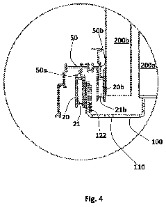
[0015] Fig.4 shows the engagement mechanism engaging a lower track of a
sliding
door in a close-up view, according to some embodiments of the present
invention.
DETAILED DESCRIPTION OF THE INVENTION
[0016] In the following detailed description of various embodiments,
reference is
made to the accompanying drawings that form a part thereof, and in which are
shown
by way of illustration specific embodiments in which the invention may be
practiced. It
is understood that other embodiments may be utilized and structural changes
may be
made without departing from the scope of the present invention.
[0017] The present invention, in some embodiments thereof, provides an
engagement mechanism for hanging sliding doors of compartments such as
closets,
cupboards and the like. The engagement mechanism is configured to support the
sliding movement of a roller such as a wheel or a spherical bearing, allowing
the lower
track, for compartment-sliding door configuration in which the lower track of
the
compartment is designed to be located above the roller.
[0018] The term "hanging sliding door" refers to a sliding door that
covers the
outer rim of the compartment for esthetical reasons to allow only viewing the
sliding
doors from a frontal view of the compartment, where the compartment's frame is
hidden by the sliding door(s) meaning that the height of the sliding door(s)
is either
equal or higher than the height of the compartment frame.
[0019] Known in the art hanging sliding doors are usually configured as
"top hung"
sliding doors, in which the sliding door is hung from above by trolley
hangers. In this
configuration the entire weight of the door is carried by the top hangers from
above.
4
CA 02877828 2014-12-23
WO 2014/016823
PCT/1L2013/050542
[0020] The present invention allows additional or alternative support of
the door's
weight from below using one or more lower sliding tracks of the compartment,
since it
offers an engaging mechanism that allows keeping each roller of one or more of
the
sliding doors engaged with its respective lower track (e.g. just the inner
sliding door or
also the outer sliding door). This allows the weight of the respective sliding
door to
additionally or alternatively be carried by lower components of the
compartment ¨ such
as by a lower track thereof engaging the roller of the engagement mechanism
from
below.
[0021] According to some embodiments of the present invention, the
engagement
mechanism includes: (i) at least one roller for rolling along a lower track;
(ii) a
connector for connecting the engagement mechanism to the respective hanging
sliding
door, where the connector includes a supporting portion, which connects to the
sliding
door and an extended portion, which connects to the roller; and (iii) an
elastic member
such as a coiled spring, which elastically connects to the roller in a manner
that allows
the roller to move along an axis of the elastic member that is substantially
perpendicular to the sliding door tracks,
[0022] According to some embodiments, the extended portion includes a
holding
member for holding the elastic member there-above in a manner that allows the
roller
to apply force from below towards the lower track of the compartment located
above
the roller for maintaining engagement between the roller and the lower track
throughout the sliding movement of the sliding door.
[0023] Reference is now made to Figures 1-2, schematically illustrating
an
engagement mechanism 100 for hanging sliding doors, according to some
embodiments of the present invention.
[0024] The engagement mechanism 100 includes a connector 110 for connecting
thereof to the sliding door that includes a supporting portion 115a, and an
extended
portion 115b. The supporting portion 115a is configured to allow connecting
thereof to
a lower portion of the respective sliding door e.g. by screwing the supporting
portion
115a to a back side lower portion of the sliding door through a designated
groove 117
in the supporting portion 115a of the connector 110.
[0025] As illustrated in figures 1-2, the engagement mechanism 100 also
includes a
wheel guide roller 20 and a coiled spring 122 elastic member. The spring 122
provides
the roller 20 with the ability to move along a vertical axis "z" (see Fig. 1)
substantially
5
CA 02877828 2014-12-23
WO 2014/016823
PCT/1L2013/050542
perpendicular to the sliding movement of the roller 20 and sliding door, in
response to
"irregularities" of the lower track. These irregularities may be, for example,
if the lower
and upper tracks of the compartment are not parallel to a very high accuracy
level in
case the compartment system includes upper tracks as well when the lower track
is not
leveled enough and/or has bumps thereover. This will be further elaborated in
the
description of Figures 3-4 showing the lower track of the compartment.
[0026] As illustrated in figures 1-2, the extended portion 115b includes
an opening
121a having a protruding member 121b at its bottom edge for holding the coiled
spring
122 thereover from below. The roller 20 includes an inner groove 21 for
receiving a
protruding lower track type for sliding thereover by rolling.
[0027] Figures 1-2 also show how the roller 20 is held by the connector
110
extended portion 115b by having a screw 25 inserted to the extended portion
115b
through it opening 121a and fastened thereto through a movable connecting
member 22
that attaches to the outer surface of the extended portion 115b, where the
screw 25 is
inserted through a designated perforation of the movable connecting member 22
and
through the opening 121a and be fastened to the extended portion 115b by using
a nut
24 and optionally also one or more 0-rings 23 to reduce friction therebetween.
[0028] As shown in Figures 1-2, the coiled spring 122 is held from below
and
therefore the lower protruding member 121b serves as a lower fixation point of
the
coiled spring 122 allowing the spring 122 to move along the "z" axis to
contract or to
stretch, in response to the vertical movements of the roller 20 when moved
along the
lower track of the respective compartment.
[0029] According to some embodiment so the present invention, as
illustrated in
Figures 1-2, the engagement mechanism 100 may also include an adjustment
mechanism 30 located at the supporting portion 110 of the connector 110. The
adjustment mechanism 30 is configured to allow adjusting the location of the
entire
connector 110 in respect to the edge of the sliding door and the tracks of the
door (the
lower track and optionally also the upper track) by including: (i) a first
adjustment
mechanism including a movable member 33 and an adjustment member 32 (e.g. a
screw 32 threaded to a designated female thread of the movable member 33) that
allows adjusting the location of the connector 110 in respect to the door
along the "z"
vertical axis by determining the thread rate of the screw 32, for example; and
(ii) an
elastic member such as another coiled spring 31 stretched along a vertical
axis of the
6
CA 02877828 2014-12-23
WO 2014/016823
PCT/1L2013/050542
connector 110 allowing fine adjustment of the connector 110 location along the
vertical
axis by enabling to contract/stretch in respect to vertical movements of the
sliding door
it connects to.
[0030] In the engagement mechanism 100 embodiments illustrated in
Figures 1-4
the roller 20 and the spring 122 are not located in the same planes ¨ meaning
that the
roller 20 is held in a slightly distant position in respect to the coiled
spring 122. The
connection of the roller 20 to the connector 110 through the movable
connecting
member 22 allows the coiled spring 122 to vertically move in response to the
roller's 20
vertical movements.
[0031] However, in other embodiments of the present invention, the coiled
spring
and roller may be located one above the other over the same plane so that they
share
the same vertical axis.
[0032] According to some embodiments of the present invention, multiple
rollers
can be connected (through one or more connectors) to the same sliding door
each
connected to a different elastic member such as a coiled spring.
[0033] In the above-described embodiments, the roller 20 includes a
groove 21 for
receiving and engaging a "protruding lower track" such as protruding lower
track 50a,
as illustrated in Fig. 4. However, in other embodiments of the present
invention, the
roller can include a substantially flattened outer rolling surface instead of
the groove as
described above. In these embodiments the lower track that should engage this
roller is
a "receptor lower track" (Not shown) configured to receive and enclose the
roller
therein. In most hanging doors protruding tracks are used for esthetical
reasons.
[0034] Reference is now made to Figures 3-4, schematically illustrating
how the
engagement mechanism 100 as described in respect to Figures 1-2 engages an
outer
protruding lower track 50a of a closet along which the roller 20 is to roll,
where the
engagement mechanism 100 is connected to an inner sliding door 200a of the
closet.
The closet, in this example, has two sliding doors: the inner sliding door
200a and an
outer sliding door 200b located in a manner that enables the doors 200a and
200b to
slide one passed the other as they are located at two different parallel
planes.
[0035] As illustrated in Fig. 4, the outer protruding lower track 50a
engages the
groove 21 of the roller 20 of the engagement mechanism 100 for supporting and
sliding
of the inner sliding door 200a. Another roller 20b having a groove 21b therein
engages
7
CA 02877828 2014-12-23
WO 2014/016823
PCT/1L2013/050542
an inner protruding lower track 50b for supporting and sliding the outer
sliding door
200b.
[0036] According to some embodiments, as illustrated in Figures 3-4, the
outer and
inner protruding lower tracks 50a and 50b, respectively, are connected (may be
integrally connected) to one another and are parts of a tracks frame-structure
50 that
connects to the closet frame. The frame-structure 50 can be a profile made of
ridged
materials such as metal or plastic that connects to the frame of the
compartment (e.g.
closet frame).
[0037] As illustrated in Fig. 4, the coiled spring 122 of the engagement
mechanism
100 allows flexibly carrying the load of the inner sliding door 200a
thereupon, since it
engages the outer protruding lower track 50a from below, where slight vertical
movements occurring when the inner sliding door 200a is slides through are
compensated by contraction or stretching of the coiled spring 122 holding the
roller 20,
keeping the roller 20 engaged with its track 50a throughout the sliding of the
door
200a.
[0038] The engagement mechanism as described above, allows overcoming
slight
errors in alignment of the lower and/or upper tracks of the compartment while
still
allowing the roller to roll through the track as well as to engage the track
throughout
the sliding movement preventing the lower track engaging the roller of the
engagement
mechanism from being thrown out of the roller groove or from the roller from
being
thrown out of the track (depending on engagement mechanism configuration) with
any
misalignment of the lower and optionally upper track or encounter with
obstacles in the
track(s) such as dirt of misconfiguration of the track in one or more
locations thereover.
[0039] Many alterations and modifications may be made by those having
ordinary
skill in the art without departing from the spirit and scope of the invention.
Therefore,
it must be understood that the illustrated embodiment has been set forth only
for the
purposes of example and that it should not be taken as limiting the invention
as defined
by the following invention and its various embodiments and/or by the following
claims. For example, notwithstanding the fact that the elements of a claim are
set forth
below in a certain combination, it must be expressly understood that the
invention
includes other combinations of fewer, more or different elements, which are
disclosed
in above even when not initially claimed in such combinations. A teaching that
two
elements are combined in a claimed combination is further to be understood as
also
8
CA 02877828 2014-12-23
WO 2014/016823
PCT/1L2013/050542
allowing for a claimed combination in which the two elements are not combined
with
each other, but may be used alone or combined in other combinations. The
excision of
any disclosed element of the invention is explicitly contemplated as within
the scope of
the invention.
[0040] The words used in this specification to describe the invention and
its various
embodiments are to be understood not only in the sense of their commonly
defined
meanings, but to include by special definition in this specification
structure, material or
acts beyond the scope of the commonly defined meanings. Thus if an element can
be
understood in the context of this specification as including more than one
meaning,
then its use in a claim must be understood as being generic to all possible
meanings
supported by the specification and by the word itself.
[0041] The definitions of the words or elements of the following claims
are,
therefore, defined in this specification to include not only the combination
of elements
which are literally set forth, but all equivalent structure, material or acts
for performing
substantially the same function in substantially the same way to obtain
substantially the
same result. In this sense it is therefore contemplated that an equivalent
substitution of
two or more elements may be made for any one of the elements in the claims
below or
that a single element may be substituted for two or more elements in a claim.
Although
elements may be described above as acting in certain combinations and even
initially
claimed as such, it is to be expressly understood that one or more elements
from a
claimed combination can in some cases be excised from the combination and that
the
claimed combination may be directed to a sub-combination or variation of a sub-
combination.
[0042] Insubstantial changes from the claimed subject matter as viewed
by a
person with ordinary skill in the art, now known or later devised, are
expressly
contemplated as being equivalently within the scope of the claims. Therefore,
obvious
substitutions now or later known to one with ordinary skill in the art are
defined to be
within the scope of the defined elements.
[0043] The claims are thus to be understood to include what is
specifically
illustrated and described above, what is conceptually equivalent, what can be
obviously
substituted and also what essentially incorporates the essential idea of the
invention.
[0044] Although the invention has been described in detail, nevertheless
changes
and modifications, which do not depart from the teachings of the present
invention,
9
CA 02877828 2014-12-23
WO 2014/016823
PCT/1L2013/050542
will be evident to those skilled in the art. Such changes and modifications
are deemed
to come within the purview of the present invention and the appended claims.