Note: Descriptions are shown in the official language in which they were submitted.
CA 02878552 2016-10-04
DOWNHOLE SLEEVE SYSTEM AND METHOD
BACKGROUND
[0001/0002] In the
drilling and completion industry, the formation of boreholes for
the purpose of production or injection of fluid is common. T he boreholes are
used for
exploration or extraction of natural resources such as hydrocarbons, oil, gas,
water, and
alternatively for CO2 sequestration. For enhancing production and increasing
extraction rates
from a subterranean borehole, the formation walls of the borehole are
fractured using a
pressurized slurry, proppant containing fracturing fluid, or other treating
fluids. The fractures
in the formation wall are held open with the particulates once the injection
of fracturing fluids
has ceased.
[0003] A conventional fracturing system passes pressurized fracturing fluid
through a tubular string that extends downhole through the borehole that
traverses the zones
to be fractured. The string may include valves that are opened to allow for
the fracturing
fluid to be directed towards a targeted zone. To remotely open the valve from
the surface, a
ball is dropped into the string and lands on a ball seat associated with a
particular valve to
block fluid flow through the string and consequently build up pressure uphole
of the ball
which forces a sleeve downhole thus opening a port in the wall of the string.
When multiple
zones are involved, the ball seats are of varying sizes with a downhole most
seat being the
smallest and an uphole most seat being the largest, such that balls of
increasing diameter are
sequentially dropped into the string to sequentially open the valves from the
downhole end to
an uphole end. Thus, the zones of the borehole are fractured in a "bottom-up"
approach by
starting with fracturing a downhole-most zone and working upwards towards an
uphole-most
zone.
[0004] While a typical frac job is completed sequentially in the bottom-up
approach, an alternating stage process has been suggested in which a first
interval is
stimulated at a toe, a second interval is stimulated closer to the heel, and a
third interval is
fractured between the first and second intervals. Such a process has been
indicated to take
advantage of altered stress in the rock during the third interval to connect
to stress-relief
fractures from the first two intervals. However, accomplishing this process
has only been
1
CA 02878552 2015-01-07
WO 2014/011336 PCT/US2013/044904
capable with intervention requiring intricate manipulation from the surface or
Intelligent Well
System ("IWS") technology.
[0005] The art would be receptive to alternative devices and methods
for
alternating a sequence of a frac job.
BRIEF DESCRIPTION
[0006] A downhole tool includes a tubular including a port; a first
ball
mechanism including a first shuttle axially movable within the tubular from a
first position
covering the port to a second position exposing the port, and a first ball
seat movable with the
first shuttle; and a second ball mechanism including a second shuttle axially
movable within
the tubular from a first position exposing the port to a second position
covering the port, and
a second ball seat movable with the second shuttle, wherein an opening of the
first ball seat is
smaller than an opening of the second ball seat.
[0007] A sleeve system usable in a non-sequential order of exposing
and
covering ports, the sleeve system includes a plurality of downhole tools, at
least one of the
downhole tools including, a tubular including a port; a
first ball mechanism including a
first shuttle axially movable within the tubular from a first position
covering the port to a
second position exposing the port, and a first ball seat movable with the
first shuttle; and a
second ball mechanism including a second shuttle axially movable within the
tubular from a
first position exposing the port to a second position covering the port, and a
second ball seat
movable with the second shuttle, wherein an opening of the first ball seat is
smaller than an
opening of the second ball seat.
[0008] A method of opening and closing a port in a downhole tubular,
the
method includes stopping a first ball with a first ball seat, the first ball
seat movable with a
first shuttle covering the port; pressurizing the tubular to move the first
shuttle and expose the
port; stopping a second ball with a second ball seat uphole of the first ball
seat, the second
ball seat movable with a second shuttle; and, pressurizing the tubular to move
the second
shuttle and close the port.
[0009] A method of completing downhole operations in a non-sequential
order
using a sleeve system having a plurality of downhole tools, the method
includes dropping a
first ball down the sleeve system into a first ball seat of a first downhole
tool; opening a first
port in the first downhole tool; dropping a second ball down the sleeve system
into a first ball
seat of a second downhole tool; opening a second port uphole of the first port
using the
second downhole tool; dropping a third ball down the sleeve system into a
second ball seat of
2
CA 02878552 2015-01-07
WO 2014/011336 PCT/US2013/044904
the second downhole tool and closing the second port; releasing the second
ball from the first
ball seat of the second downhole tool, and releasing the third ball from the
second downhole
tool, the second ball landing on a first ball seat of a third downhole tool;
and opening a third
port downhole of the second port and uphole of the first port using the third
downhole tool.
BRIEF DESCRIPTION OF THE DRAWINGS
[0010] The following descriptions should not be considered limiting
in any way.
With reference to the accompanying drawings, like elements are numbered alike:
[0011] FIG. 1 depicts a cross sectional view of a portion of a
downhole sleeve
and port tool incorporating an exemplary embodiment of that downhole tool;
[0012] FIGS. 2-10 depict cross sectional views of the portion of the
exemplary
embodiment of the downhole tool of FIG. 1 in an exemplary actuation sequence;
and
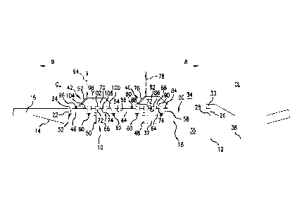
[0013] FIG. 11 depicts a side view of an exemplary embodiment of the
sleeve
system of FIG. 1, having multiple downhole tools, in a borehole and depicting
an exemplary
frac stage order;
DETAILED DESCRIPTION
[0014] A detailed description of one or more embodiments of the
disclosed
apparatus and method are presented herein by way of exemplification and not
limitation with
reference to the Figures.
[0015] An exemplary embodiment of a sleeve system 10 for permitting a
fracturing or acid job to be completed with the stages out of sequence with
respect to their
position in a borehole 12 is shown in FIGS. 1-10. By "out of sequence", it
should be
understood that the sleeve system 10 described herein enables fracturing or
acid jobs to be
completed, using a series of downhole tools 14, in a sequence such as, but not
limited to the
first operation "1" being closest to a toe in the downhole direction 8, the
second operation "2"
being further uphole of the first operation "1", the third operation "3" being
accomplished at
a location between the first and second operations, and so on, with an
operation "6" being a
most uphole operation accomplished in this particular sequence, as will be
described below
with respect to FIG. 11. While the sleeve system 10 is suitable for permitting
a fracturing or
acid job with the stages out of sequence, the sleeve system 10 described
herein is also usable
for permitting jobs in other sequences, including a conventional sequence
where an order of
operations is completed in a "bottom-up" approach as well as usable in jobs
other than
fracturing or acid jobs.
3
CA 02878552 2015-01-07
WO 2014/011336 PCT/US2013/044904
[0016] With reference to FIG. 1, a half-section of a portion of an
exemplary
embodiment of a downhole tool 14 or sleeve, such as a fracturing tool, is
shown. The tool 14
includes a tubular 16, having a centerline CL, which is disposed in the
borehole 12. The
tubular 16 includes a ported sleeve valve 18 either mounted on the tubular 16
or forming a
portion of the tubular 16. Within the sleeve valve 18, a radial indentation 20
having a ledge
22 at a first end 24, such as an uphole end, and a stop 26 at a second end 28,
such as a
downhole end. Also at the second end 28, and radially inward of the stop 26, a
shifting step
30 protrudes longitudinally towards the first end 24 of the radial indentation
20. The sleeve
valve 18 also includes a port 32, that is a lateral aperture, which provides
access between an
interior 34 of the tubular 16 and an annulus 36 of the borehole 12 between the
tubular 16 and
a formation wall 38 of the borehole 12. While only one port 32 is shown, it
should be
understood that several radially spaced apart ports 32 may be provided about a
circumference
of the sleeve valve 18.
[0017] Positioned radially inside of the sleeve valve 18 are a first
ball
mechanism 40, such as an opening ball mechanism, and a second ball mechanism
42, such as
a closing ball mechanism. The first ball mechanism 40 includes a first shuttle
44, alternately
termed a first shuttle sleeve, such as an opening shuttle, and the second ball
mechanism 42
includes a second shuttle 46 or second shuttle sleeve, such as a closing
shuttle. The first and
second shuttles 44, 46 are in stacked longitudinal positions within the radial
indentation 20 of
the sleeve valve 18. That is, the first shuttle 44 is positioned closer to the
second end 28 of
the radial indentation 20 than the second shuttle 46, even when the
longitudinal positionings
of the first and/or second shuttles 44, 46 changes. In a run-in condition, as
shown in FIG. 1,
the first shuttle 44 is connected to the sleeve valve 18 by a release member
48, such as a shear
screw, in a position where the first shuttle 44 is covering the port 32, and
the second shuttle
46 is connected to the sleeve valve 18 by a release member 50, such as a shear
screw, in a
position where a first end 52 of the second shuttle 46 is adjacent the first
end 24 of the radial
indentation 20, and a second end 54 of the second shuttle 46 is adjacent a
first end 56 of the
first shuttle 44. A second end 58 of the first shuttle 44 faces, but is spaced
from, the second
end 28 of the radial indentation 20. Seals 60, such as 0-ring seals, are
interposed between the
first and second shuttles 44, 46 and the sleeve valve 18. The first and second
shuttles 44, 46
may include radial indentations 62 on exterior surfaces 64, 66 thereof to
receive the seals 60
therein. Interior surfaces 68, 70 of the first and second shuttles 44, 46
include one or more
engagement voids 72, for a purpose that will be described below. Adjacent each
engagement
void 72 is an engagement protrusion 74, such that the engagement voids 72 and
protrusions
4
CA 02878552 2015-01-07
WO 2014/011336 PCT/US2013/044904
74 are alternatingly arranged. In the run-in position shown in FIG. 1, access
between the
annulus 36 and the interior 34 of the tubular 16 is prevented through the port
32 because the
first shuttle 44 is positioned to cover the port 32.
[0018] The first ball mechanism 40 further includes a first ball seat
76, such as
an opening ball seat, extending from the first shuttle 44. The first ball seat
76 includes a
truncated conical shape for receiving a ball therein if the ball has a greater
diameter than a
diameter of an opening 78 in the first ball seat 76, or for passing a ball
therethrough if the ball
has a smaller diameter than the opening 78 in the first ball seat 76. A seal
80, such as an 0-
ring seal, is positionable between the first ball seat 76 and the first
shuttle 44. The first ball
seat 76 is supported by a first ball seat support 82, where the first ball
seat support 82 extends
further in a downhole direction than the first ball seat 76. The first ball
seat support 82 is
secured to the first shuttle 44 by a release member 84, such as a shear screw.
The first ball
seat support 82 includes one or more engagement voids 86 on an interior
surface 88 thereof.
Adjacent each engagement void 86 is an engagement protrusion 90 in an
alternating pattern.
In the run-in position, the engagement protrusions 90 of the first ball seat
support 82 abut
with the engagement protrusions 74 of the first shuttle 44.
[0019] The second ball mechanism 42 similarly includes a second ball
seat 92,
such as a closing ball seat, extending from the second shuttle 46. The second
ball seat 92
includes a truncated conical shape for receiving a ball therein if the ball
has a greater
diameter than an opening 94 in the second ball seat 92, or for passing a ball
therethrough if
the ball has a smaller diameter than the opening 94 in the second ball seat
92. A seal 96, such
as an 0-ring seal, is positionable between the second ball seat 92 and the
second shuttle 46.
The second ball seat 92 is supported by a second ball seat support 98, where
the second ball
seat support 98 extends further in a downhole direction than the second ball
seat 92. The
second ball seat support 98 is secured to the second shuttle 46 by a release
member 100, such
as a shear screw. The second ball seat support 98 includes one or more
engagement voids
102 on an interior surface 104 thereof. Adjacent each engagement void 102 is
an engagement
protrusion 106 in an alternating pattern. In the run-in position, the
engagement protrusions
106 of the second ball seat support 98 abut with the engagement protrusions 74
of the second
shuttle 46.
[0020] In the illustrated embodiment, the second ball seat 92 is
positioned
further uphole than the first ball seat 76, and the first ball seat 76 extends
further radially
inward than the second ball seat 92. That is, the first ball seat 76 has a
smaller opening 78
than an opening 94 of the second ball seat 92.
CA 02878552 2016-10-04
, .
[0021] FIGS. 2-10 show an actuation sequence of an exemplary method of
employing the tool 14 shown in FIG. 1. As shown in FIG. 2, a first ball 108 is
passed
through the ported sleeve valve 18 and tubular 16 in the downhole direction 8
to actuate tools
(not shown) further downhole. In order for the first ball 108 to pass the
second ball seat 92
and then the first ball seat 76, the first ball 108 has a diameter less than a
size of the openings
94, 78 of the second and first ball seats 92, 76 so as not to become trapped
therein.
[0022] Then, as shown in FIG. 3, a second ball 110 is passed into the ported
sleeve valve 18. The second ball 110 has a diameter that is larger than the
diameter of
the first ball 108, smaller than the opening 94 of the second ball seat 92,
and larger than the
opening 78 of the first ball seat 76. Due to the second ball 110 having a
smaller diameter
than the opening 94 of the second ball seat 92, the second ball 110 passes
through the second
ball seat 92 and the second ball seat support 98 as shown in FIG. 3. Due to
the second ball
110 having a larger diameter than the opening 78 of the first ball seat 76,
the second ball 110
lands on the first ball seat 76 as shown in FIG. 4.
[0023] Turning now to FIG. 5, after the second ball 110 lands on the first
ball
seat 76, pressure is supplied within the tubular 16 uphole of the second ball
110. Pressure is
thus applied to the second ball 110, which in turn applies pressure to the
first ball seat 76, the
first ball seat support 82, and the first shuttle 44 connected to the first
ball seat support 82 via
the release member 84. With pressure applied to the first shuttle 44 in a
first direction (such
as the downhole direction 8), the first shuttle 44 is sheared or otherwise
released from the
sleeve valve 18 by a releasing or shearing of the release member 48. Once the
first shuttle 44
is separated from the sleeve valve 18, the pressure on the second ball 110
pushes the first ball
seat 76, first ball seat support 82, and connected first shuttle 44 in the
downhole direction 8
until the first ball seat support 82 abuts with the shifting step 30. Movement
of the first
shuttle 44 in the downhole direction 8 uncovers the port 32 in the sleeve
valve 18, and thus
the first ball mechanism 40 is an opening ball mechanism because it is capable
of opening the
port 32. At this point, the second ball 110 has enabled the opening of the
port 32 and a
fracturing job, slurry, acid job, and the like may be pumped through the port
32, although
alternative downhole procedures may also be accomplished through the port 32.
[0024] Turning now to FIG. 6, at a subsequent time, such as after a job is
completed through the port 32, a third ball 112 is dropped into the tubular
16. The
third ball 112 has a larger diameter than both the first ball 108 and the
second ball 110. The
third ball 112 also has a larger diameter than the opening 94 of the second
ball seat 92. When
the third ball 112 reaches the second ball seat 92, it lands on the second
ball seat as shown in
6
CA 02878552 2015-01-07
WO 2014/011336 PCT/US2013/044904
FIG. 6. Pressure is supplied within the tubular 16 uphole of the third ball
112. Pressure is
thus applied to the third ball 112, which in turn applies pressure to the
second ball seat 92,
second ball seat support 98, and the second shuttle 46 connected to the second
ball seat
support 98 by the release member 100. With pressure applied to the second
shuttle 46 in the
direction 8, the second shuttle 46 is sheared or otherwise released from the
sleeve valve 18 by
a shearing or releasing of the release member 50.
[0025] As shown in FIG. 7, once the second shuttle 46 is separated
from the
sleeve valve 18, continued pressure on the third ball 112 pushes the second
ball seat 92,
second ball seat support 98, and second shuttle 46 in the direction 8 such
that the second
shuttle 46 covers and closes the port 32. Thus, the second ball mechanism 42
is a closing ball
mechanism due to its ability to close the port 32. The second shuttle 46 moves
in the
direction 8 until the second shuttle 46, such as the second end 54 of the
second shuttle 46,
abuts with the first shuttle 44, such as the first end 56 of the first shuttle
44.
[0026] With reference to FIG. 8, pressure applied to the third ball
112 transfers
force through the second ball seat 92, the second ball seat support 98, the
release member
100, the second shuttle 46, the first shuttle 44, release member 84, and first
ball seat support
82 to the shifting step 30. The release member 84 that secured the first ball
seat support 82 to
the first shuttle 44 is sheared or otherwise released when the first shuttle
44 is pushed in the
direction 8 towards the stop 26 but the first ball seat support 82 is
prevented from moving in
the direction 8 by the shifting step 30.
[0027] FIG. 9 shows the first shuttle 44 translated axially relative
to the first ball
seat 76 and first ball seat support 82, allowing the first ball seat support
82 to collapse
radially outward into the engagement voids 72 of the first shuttle 44. To
translate axially in
direction 8, the first shuttle 44 moves toward the stop 26 at the second end
28 of the radial
indentation 20 of the sleeve valve 18. That is, prior to axial translation of
the first shuttle 44
relative to the first ball seat support 82, the engagement protrusions 74 of
the first shuttle 44
are aligned with the engagement protrusions 90 of the first ball seat support
82, and the
engagement voids 72 of the first shuttle 44 are aligned with the engagement
voids 86 of the
first ball seat support 82 as shown in FIG. 1. After axial translation of the
first shuttle 44 as
shown in FIG. 9, the engagement protrusions 90 of the first ball seat support
82 mesh, nest, or
otherwise collapse within the engagement voids 72 of the first shuttle 44 and
the engagement
protrusions 74 of the first shuttle 44 nest within the engagement voids 86 of
the first ball seat
support 82. The first ball seat support 82 may be segmented such that the
segmentation
thereof allows for the change in internal diameter. It should be understood
that segments of
7
CA 02878552 2015-01-07
WO 2014/011336 PCT/US2013/044904
the first ball seat support 82 are clustered closer together in FIG. 1 than in
FIG. 9. After the
first ball seat support 82 expands radially outward into the first shuttle 44,
pressure uphole of
the second ball 110 (shown previously in FIG. 8) also forces radial outward
deformation of
the first ball seat 76, allowing the second ball 110 to move past the first
ball seat 76 and
further down the tubular 16 in direction 8.
[0028] As shown in FIG. 10, additional pressure on the third ball 112
will cause
the release member 100 to shear or otherwise release, allowing the second ball
seat support
98, which may also include segmentation, to collapse radially outward into the
engagement
voids 72 of the second shuttle 46. That is, prior to the additional pressure
on the third ball
112, the engagement protrusions 74 of the second shuttle 46 are aligned with
the engagement
protrusions 106 of the second ball seat support 98, and the engagement voids
72 of the
second shuttle 46 are aligned with the engagement voids 102 of the second ball
seat support
98 (as shown in FIG. 1). After the additional pressure is applied on the third
ball 112 and the
release member 100 is broken, the engagement protrusions 106 of the second
ball seat
support 98 mesh, nest, or otherwise collapse within the engagement voids 72 of
the second
shuttle 46 and the engagement protrusions 74 of the second shuttle 46 nest or
otherwise fit
within the engagement voids 102 of the second ball seat support 98. Pressure
uphole of the
third ball 112 then forces radial outward deformation of the second ball seat
92, allowing the
third ball 112 to pass the second ball seat 92 and move axially down the
tubular 16 in the
direction 8. In an exemplary embodiment, the first, second, and third balls
108, 110, and 112,
may be made from a material that dissolves or disintegrates after a
predetermined time such
that they do not need to flow back in direction 9.
[0029] The present invention provides means to realize the method of
altering
the sequence of the frac job or other stimulation. In one exemplary
embodiment, devices
described herein may be alternated in sequence up the borehole with industry
accepted
conventional single ball shifted sleeves. FIG. 11 illustrates the sleeve
system 10 within
borehole 12, the borehole 12 extending from an uphole location 116, such as a
surface, to a
downhole location 118. The borehole 12 may be a horizontal borehole as shown,
and the
sleeve system 10 includes a heel portion 120 at a bend of the sleeve system
10, and a toe
portion 122 at a downholemost end of the sleeve system 10. Packers and/or
anchors 114
isolate sections of the annulus 36 surrounding the ports 32. The sleeve system
10 may
further include any number of tubulars to complete the string. An exemplary
order of
operations is indicated within the borehole 12, with "Frac 1" indicating that
the ports 32
nearest the toe portion 122 are opened first using Ball A. Frac "2" indicates
that the ports 32
8
CA 02878552 2015-01-07
WO 2014/011336 PCT/US2013/044904
further uphole from the toe portion 122 are opened next using Ball B to
operate the tool 14
shown in FIG. 1 and the ports are subsequently closed using Ball C after
completion of Frac
"2". Frac "3" indicates that the ports 32 between the locations for Frac "1"
and Frac "2" are
opened third using the Ball B which was released from the Frac "2" location.
Subsequently,
Frac "4" indicates that the ports 32 further uphole from the Frac "2" location
are opened next
using Ball D and are subsequently closed using Ball E after completion of Frac
"4". Frac "5"
indicates that the ports 32 between the locations for Frac "4" and Frac "2"
are opened using
the Ball D which was released from the Frac "4" location. Then, Frac "6"
indicates that the
ports 32 are opened further uphole from the location of Frac "4" using a Ball
F, and are
subsequently closed using Ball G. Frac "7" indicates that the ports 32 between
the locations
for Frac "6" and Frac "4" are opened using the Ball F that is released from
the Frac "6"
location. While seven fracturing locations are shown, any number of fracturing
locations
may be addressed using the sleeve system 10, which may include any number of
downhole
tools 14 and conventional ball shifted sleeves in alternating locations. Thus,
a method is
provided for employing a sleeve system 10 having a series of downhole tools 14
in an
alternative fracturing order of operations, using balls and sleeves instead of
intervention or
IWS technology. In the exemplary embodiment shown in FIG. 11, the sleeves for
stages 1, 3,
5, and 7 are standard sleeves, while the downhole tools 14 are employed for
stages 2, 4, and
6.
[0030] The exemplary sleeve system 10 described herein permits the
stimulation
of a reservoir with a "ball and sleeve" multistage stimulation system with the
stages out of
sequence with respect to their position in the borehole 12. The exemplary
embodiments
described herein would allow for a change from a typical frac job employing
the traditional
"bottom up" approach (performed sequentially from a downhole location, such as
a toe, to a
more uphole location such as a heel) to an alternating stage process in which
a first interval is
stimulated near a toe, a second interval is stimulated closer to a heel, and a
third interval is
fractured between the first and second intervals. . This change in sequence
changes the
characteristics of pressurization of the formation during a pressure
stimulation of a reservoir.
[0031] While the invention has been described with reference to an
exemplary
embodiment or embodiments, it will be understood by those skilled in the art
that various
changes may be made and equivalents may be substituted for elements thereof
without
departing from the scope of the invention. In addition, many modifications may
be made to
adapt a particular situation or material to the teachings of the invention
without departing
from the essential scope thereof. Therefore, it is intended that the invention
not be limited to
9
CA 02878552 2015-01-07
WO 2014/011336 PCT/US2013/044904
the particular embodiment disclosed as the best mode contemplated for carrying
out this
invention, but that the invention will include all embodiments falling within
the scope of the
claims. Also, in the drawings and the description, there have been disclosed
exemplary
embodiments of the invention and, although specific terms may have been
employed, they
are unless otherwise stated used in a generic and descriptive sense only and
not for purposes
of limitation, the scope of the invention therefore not being so limited.
Moreover, the use of
the terms first, second, etc. do not denote any order or importance, but
rather the terms first,
second, etc. are used to distinguish one element from another. Furthermore,
the use of the
terms a, an, etc. do not denote a limitation of quantity, but rather denote
the presence of at
least one of the referenced item.