Note: Descriptions are shown in the official language in which they were submitted.
CA 02878630 2015-01-07
WO 2014/011953 PCT/US2013/050194
INTEGRATED OIL PRODUCTION AND UPGRADING USING A
MOLTEN ALKALI METAL
RELATED APPLICATIONS
[0001] This application claims the benefit of U.S. Provisional Patent
Application
Serial No. 61/671,228 filed July 13, 2012. This application is also a
continuation-in-
part of U.S. Patent Application Serial No. 12/916,984, filed November 1, 2010,
entitled "UPGRADING OF PETROLEUM OIL FEEDSTOCKS USING ALKALI
METALS AND HYDROCARBONS", which application claims the benefit of U.S.
Provisional Patent Application Serial No. 61/257,369 filed November 2, 2009,
entitled
"UPGRADING OF PETROLEUM OIL FEEDSTOCKS USING ALKALI METALS AND
HYDROCARBONS". This application is also a continuation-in-part of U.S. Patent
Application Serial No. 13/753,918, filed January 30, 2013, entitled "PROCESS
FOR
DESULFURIZING PETROLEUM FEEDSTOCKS", which application claims the
benefit of U.S. Provisional Patent Application Serial No. 61/594,846 filed
February 3,
2012 entitled "PROCESS FOR DESULFURIZING PETROLEUM FEEDSTOCKS
AND RECOVERING ALKALI METALS AND SULFUR FROM ALKALI METAL
SULFIDES AND POLYSULFIDES". All of these prior patent applications are
expressly incorporated herein by reference.
U.S. GOVERNMENT INTEREST
[0002] This invention was made with government support under Contract No.
DE-
FE0000408 awarded by the U.S. Department of Energy, National Energy
Technology Laboratory. The government has certain rights in the invention.
1
CA 02878630 2015-01-07
WO 2014/011953 PCT/US2013/050194
TECHNICAL FIELD
[0003] The present disclosure relates to a process for integrating a
process for
removing nitrogen, sulfur, and heavy metals from sulfur-, nitrogen-, and metal-
bearing shale oil, bitumen, or heavy oil with a process for forming the shale
oil,
heavy oil, bitumen. Such an integration of these two processes provides added
efficiencies that are not otherwise available.
BACKGROUND
[0004] U.S. Patent Application Serial No. 12/916,984 (which has been
incorporated herein by reference) has been published as United States Patent
Application Publication No. 2011/0100874. The reader is presumed to be
familiar
with the disclosure of this published application. This published application
will be
referred to herein as the "874 application."
[0005] U.S. Patent Application Serial No. 13/753,918 (which has been
incorporated herein by reference) has been published as United States Patent
Application Publication No. 2013/0140217. The reader is presumed to be
familiar
with the disclosure of this published application. This published application
will be
referred to herein as the "217 application."
[0006] Both the '217 application and the '874 application teach the
utilization of
hydrocarbons such as methane to attach to radicals formed when an alkali metal
such as sodium reacts with the heteroatoms or metals atoms contained within
the
feedstock. This use of hydrocarbons in the above-recited applications replaces
hydrogen gas which has traditionally been used when reacting sodium with oil.
For
example, U.S. Patent Nos. 3,788,978, 3,791,966, 4,076,613 all disclose the use
of
hydrogen gas when sodium metal is reacted with oil.
2
CA 02878630 2015-01-07
WO 2014/011953 PCT/US2013/050194
[0007] However, the use of hydrogen with sodium and oil has several
disadvantages. One such disadvantage is that the hydrogen used in these
sodium/oil
reactions is typically produced via the "steam methane reforming process."
This
process is generally discouraged because, during this process, carbon
dioxide¨a
greenhouse gas¨is emitted. Thus, alternative radical capping substances (e.g.,
organic materials) may be preferred over hydrogen.
[0008] When an alkali metal reacts with a petroleum feedstock and interacts
with
heteroatoms such as metals, sulfur and nitrogen in the feedstock, the metals,
heteroatoms, etc. will be reduced to form the metals themselves as well as
alkali
metal sulfides and nitrides. During this reaction, organic radicals may be
formed
which preferably are reacted with a substance other than the same organic
molecule
originally bonded to the heteroatom or with another feedstock molecule. If the
radical reacts with the organic molecule originally bonded to the heteroatom,
undesirable coking may occur. Likewise, if the radical reacts with another
feedstock
molecule, undesirable polymerization may occur. For this reason, an additional
radical-capping species, such as methane, etc., is used in the reaction.
[0009] It would be beneficial however, if this process for upgrading the
oil
feedstock material (using an alkali metal) could be integrated with the
process for
forming the feedstock (e.g., the process for extracting the heavy oil, oil
shale, shale
gas, etc.) Such "integration" could provide additional benefits and could
result in
increased efficiencies. Such an integration process is disclosed herein.
SUMMARY
[0010] The present embodiments relate to a method for upgrading an oil
feedstock using an alkali metal, such as sodium, as a means of removing
nitrogen,
sulfur and heavy metals from the oil feedstock material. At the same time,
this
3
CA 02878630 2015-01-07
WO 2014/011953 PCT/US2013/050194
upgrading process can be integrated with other processes used to obtain the
oil
feedstock, thereby resulting in increased efficiencies.
[0011] The present embodiments relate to the use of radical capping
substances
(or radical forming substances) that will react with the oil feedstock in the
presence
of sodium or another alkali metal. These other radical forming substances may
be
more readily available than hydrogen. (These other radical forming substances
would not be reactive and would not provide any benefit without the sodium.)
By
way of example, such radical forming substances include methane, ethane,
propane,
butane, pentane, hexane and their isomers. Other hydrocarbons (such as octane
or
other carbon containing compounds containing one or more carbon atoms) may
also
be used. The hydrocarbon may be a gas and may be comprised of a mixture of
hydrocarbon gases (such as natural gas, or shale gas ¨ the gas produced by
retorting oil shale).
[0012] In addition to the aforementioned radical capping substances, other
substances may be considered, for example: natural gas containing H25. If H25
is in
the natural gas, more sodium may be required to obtain the same results since
sodium reacts with the H25 in the natural gas (in addition to the reaction of
sodium
with the oil feedstock) to form H2 and sodium sulfide. Thus H25 ultimately in
the
presence of sodium can provide hydrogen that can react with the radicals
formed
with heteroatom removal. Also, ethene, propene, butane, pentene, hexane,
heptene,
octane and their isomers may be used. Additionally, H25 formed in the retort
process or oil production process may be utilized for this purpose.
[0013] To improve productivity, reduce overall emissions, and improve
overall
process economics, several opportunities exist to integrate the process of
upgrading
the oil feedstock with the process of extracting/obtaining the feedstock
itself. For
4
CA 02878630 2015-01-07
WO 2014/011953 PCT/US2013/050194
example, certain feedstocks (such as heavy oil and shale oil) also require
heat
during the extraction/processing. This heat is used to promote the endothermic
retorting reactions of in situ or surface retort operations. It has been found
that the
fuel needed for this heating process can be obtained as byproducts from the
upgrading process. Thus, in this manner, integrating these two processes may
create efficiencies not otherwise available. With regard to oil shale,
retorting is a
process where the oil shale is heated directly or indirectly to temperature
between
300-550 C (in an oxygen free environment). This retorting process transforms
the
kerogen contained within the shale rock into oil and gas. The retorting
process may
be conducted batchwise, continuously, on the surface above ground or
underground
at the location of the oil shale deposit. If combined with the upgrading
process, the
upgrading process can provide the fuels necessary to provide the heat used in
the
retorting process.
[0014] Further, certain feedstocks, such as heavy oil, require directed
heating or
heating water to produce steam (for a steam assisted gravity drainage (SAGD)
operation); these processes can use the byproducts of the upgrading process as
the
fuel necessary to create the requisite heat. Thus, integrating these two
processes
may create efficiencies.
[0015] Heavy oil production, or bitumen production or shale oil production
are
considered separate from the upgrading and typically are performed at
different
locations, maybe hundreds of miles apart. However, the present embodiments
promote efficiency by integrating these two processes.
[0016] As mentioned above, methane, hydrogen sulfide, and shale gas and can
serve as the radical capping agent needed when radicals are formed following
reaction of an alkali metal with the feedstock. Gases such as methane,
hydrogen
CA 02878630 2015-01-07
WO 2014/011953 PCT/US2013/050194
sulfide and shale gas are produced during the retorting processes (as
byproducts).
Thus the gas formed during retorting can be used in the upgrading process if
these
processes are co-located and integrated.
[0017] As oil sands or bitumen or heavy oil are heated directly (or reacted
using
steam), methane gas and hydrogen sulfide gas may form in the process. These
gases may be fed into the upgrading process where the methane may serve
directly
as a radical capping material. The hydrogen sulfide, in the presence of the
alkali
metal, will produce a quantity of hydrogen gas and this in situ formed
hydrogen may
act as the radical capping agent. Thus, the gases (byproducts) formed during
the
heating of bitumen/heavy oil may be used in the upgrading process. There are
advantages to using the gases formed in the extraction of heavy oil or oil
sands or
bitumen by feeding those gases into the alkali metal upgrading process. An
additional advantage is that the hydrogen sulfide, a poisonous gas is
essentially
converted to useful substances.
[0018] Similarly, when retorting oil shale, the gases formed may be used as
radical capping agent in the upgrading process. An additional advantage is
that often
hydrogen sulfide is formed in the retorting process and the gases would
require
scrubbing of the hydrogen sulfide before the gases could be otherwise used.
However, since upgrading with alkali metal consumes the hydrogen sulfide, the
overall process becomes more efficient. For example, normally the shale gas
would
require considerable processing to remove the hydrogen sulfide, but this
removal of
the hydrogen sulfide occurs automatically in the upgrading process.
[0019] Other ways where the process integration is beneficial is where heat
is
required for the oil production process. This heat may be required for the
generation
of steam (for a steam assisted gravity drain process) or during the heating of
heavy
6
CA 02878630 2015-01-07
WO 2014/011953 PCT/US2013/050194
Oil to reduce the viscosity. Following alkali metal upgrading and the
dissolution of the
alkali metal sulfide, there is a resulting solid organic matter or portion
which may be
1-10% of the starting oil weight. This matter may be used as a fuel to produce
the
requisite heat. These solids may also be used in part as a fuel source for the
retort.
In addition, this matter may be fed in part or in whole back into the retort
where a
thermal cracking process may be assisted by the fine metals (which may be
present
in the solid). Feeding the solids back into the retort can provide two
benefits. First,
the overall liquid output can be increased. Second, the fine metals in the
organic
matter increase the effectiveness of the retorting process by serving as a
catalyst. By
increasing the effectiveness, the retort temperature may be reduced and the
liquid
yield may improve.
[0020] In the present embodiments, the alkali metal sulfide (formed during
the
upgrading process) is regenerated electrochemically (into sulfur and alkali
metal)
using cells with ceramic membranes. The power required to operate the cells
may be
produced using a generator that co-produces heat. This heat can also be used
in
part to provide the heat required for heavy oil or bitumen production or to
heat a
retort, as outlined herein. Thus, there are a variety of different ways in
which the
combining/integration of these processes produces efficiencies.
BRIEF DESCRIPTION OF THE DRAWINGS
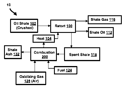
[0021] Figure 1 shows a schematic drawing for a surface oil retorting
process;
[0022] Figure 2 shows a schematic drawing of the process of Figure 1 that
has
been integrated with an upgrading process utilizing a quantity of molten
alkali metal;
[0023] Figure 3 shows a schematic drawing of an in situ oil retorting
process or
process for production of heavy oil;
7
CA 02878630 2015-01-07
WO 2014/011953 PCT/US2013/050194
[0024] Figure 4 shows a schematic drawing of the process of Figure 3 that
has
been integrated with an upgrading process utilizing a quantity of molten
alkali metal;
[0025] Figure 5 shows a schematic drawing of a steam assisted gravity drain
(SAGD) process for production of heavy oil or oil sands bitumen; and
[0026] Figure 6 shows a schematic drawing of the process of Figure that has
been integrated with an upgrading process utilizing a quantity of molten
alkali metal;
DETAILED DESCRIPTION
[0027] The present embodiments relate to integrating the process for
obtaining/extracting an oil feedstock with a process for upgrading the oil
feedstock
using an alkali metal (such as a molten alkali metal). In some embodiments,
the
alkali metal may be sodium, lithium, potassium or alloys of these metals. The
term
"oil feedstock" refers to oil sources such as heavy oil, bitumen and shale
oil.
Typically, these oil feedstock materials are upgraded to remove sulfur,
nitrogen and
heavy metals contained therein. However, by integrating the "upgrading"
process
with the retorting or production process, as described herein, efficiencies
may be
achieved. As noted above, typically these two processes are done separately
and at
locations hundreds of miles apart; however, by performing all of these
processes at
the same facility, significant advantages may be obtained.
[0028] It should be noted that the upgrading process that is outlined herein
is
described, at length, in the '874 application and the '217 application. For
purposes
of brevity, much of the descriptions regarding these upgrading processes will
be
omitted.
[0029] Referring now to Figure 1, a schematic drawing for a surface oil
retorting
process 10 is illustrated. As shown by Figure 1, the retort 100, receives oil
shale 102
which typically has been mined, brought to the surface and crushed. (The
process
8
CA 02878630 2015-01-07
WO 2014/011953 PCT/US2013/050194
for mining, bringing the material to the surface and crushing the oil shale
102 is not
shown in Figure 1, but is known in the art.) The retort 100 also received heat
from a
combustion process 200. As the oil shale 102 is heated in a substantially
oxygen
free environment, the organic content within the material transforms,
converting to
shale oil 112 and shale gas 116.
[0030] The solids leaving the retort are referred to as "spent shale" 118. The
spent shale 118 may contain both organic and inorganic material and may be
already warm (e.g., warm from the heat that was added during the retort
process
100). The spent shale 118 may be fed into the combustion process 200 as be
consumed as fuel. An additional quantity of fuel 124 may also be used in the
combustion process 200. The fuel 124 may consist in part of shale gas 116,
shale oil
112, or other sources. An oxidizing gas 128, typically air (but may be another
gas), is
fed into the combustion process 200 to react with the spent shale 118 and fuel
124.
The solids leaving the combustion process 200 have very little organic
composition
and are then suitable for various purposes such as building material or road
material.
These residual solids are referred to as "shale ash" 132. Often the retort 100
and
combustion 200 are integrated for more efficient heat transfer from the
combustion
process 200 to the retort 100.
[0031] Figure 2 shows a schematic drawing of the process of Figure 1 that
has
been integrated with an upgrading process utilizing a quantity of molten
alkali metal.
Accordingly, Figure 2 shows a surface oil retorting process 10a that is
integrated with
the upgrading technology of the '874 application. More specifically, Figure 2
shows
a process flow diagram where the same elements from Figure 1 exist but now
there
is integration with an upgrading process utilizing molten alkali metal.
9
CA 02878630 2015-01-07
WO 2014/011953 PCT/US2013/050194
[0032] In the specific example of Figure 2, sodium is the alkali metal. Of
course,
other alkali metals could also be used such as lithium, or potassium. There
are
several objectives of the upgrading process, the primary objective is to
remove
sulfur, nitrogen and metals from the shale oil 112. Another objective is to
utilize the
shale gas 116 as the radical capping agent to cap radicals formed when the
sodium
reacts with the sulfur, nitrogen, and metals. Utilizing shale gas 116
substantially, if
not entirely, reduces the need for hydrogen which typically is used in
upgrading
processes. Another objective is to de-sulfurize the shale gas 116 which may
contain
hydrogen sulfide but will be free of hydrogen sulfide after flowing through
the
upgrading process which scavenges sulfur.
[0033] As shown in Figure 2, shale gas 116 and shale oil 112 are fed into
an
upgrading reactor 300 as well as sodium metal 140. (The sodium metal 140 may
be
obtained from an electrolysis process, as will be discussed herein, thereby
allowing
the sodium metal 140 to be consistently reused.) As will be described herein,
hot
gases 178 from the power generator, may be added to the upgrade reactor 300 to
facilitate the upgrading reaction. Additionally, and/or alternatively, these
hot gases
179 from the power generator may also be added to the retort process 100.
[0034] The gas exiting the upgrading reactor 300 is substantially sulfur
free. This
gas is referred to as "desulfurized gas" 142. This sulfur-free gas 142 may
then be
used in a power generation process (e.g., it may be burned to provide
electrical
power, as desired). Other gases may also be vented off 143, as desired.
[0035] The solids and liquids from the upgrade reactor 300 move to a
solid/liquid
separator 400. In some embodiments, this separator 400 may comprise a filter
or
centrifuge, hydrocyclone, or another similar device that is designed to
separate solid
materials from liquid materials.
CA 02878630 2015-01-07
WO 2014/011953 PCT/US2013/050194
[0036] The
liquids exiting the separator 400 are substantially free of sulfur,
nitrogen, and metals and normally would be suitable for feed to an oil
refinery. These
liquid materials may be referred to as the desulfurized oil product 144. The
obtained
solids contain organics, sodium sulfide, and the metals originally contained
in the
shale oil. To facilitate separation of the sulfides from the remaining solids,
they are
fed to the solids pretreatment 500 according to the '217 application.
This
pretreatment step 500 may involve heating the solids to a temperature above
400 C
and preferably above 500 C environment with low oxygen and water
concentration,
until a weight loss occurs in the solids corresponding with an increase in the
carbon
to hydrogen ratio. The gas 150 evolves from the solids pretreatment step 500
that is
mostly methane and can be fed either to power generation 900 or to combustion
200.
[0037]
Following the solids pretreatment 500, the solids are fed to dissolution 600
where the sodium sulfide dissolves cleanly from the solids. Suitable solvents
include
formamide, methyl formamide, dimethyl formamide, acetamide, methyl acetamide,
dimethyl acetamide, ethylene glycol, propylene glycol, 1,2-ethanediol, 1,2-
propanediol, propylene carbonate, ethylene carbonate, diethyl carbonate, N-
methyl
pyrrolidone, tetraethylene glycol dimethyl ether (tetralglyme), acetonitrile,
dimethyl
sulfoxide, liquid ammonia, methyl amine methyl formamide, N,N'-
dimethylpropyleneurea (DMPU). Following dissolution 600 of the sodium sulfide,
the
solids and liquids flow to a solid liquids separation 700. This separator 700
may
comprise any device that is capable of separating solids/liquids, including a
filter or
centrifuge, hydrocyclone. The liquids 801 flow to the electrolysis 800 where
sodium
is electrochemically removed from the sulfide to form elemental sodium 140 and
elemental sulfur 155. This sodium 140 may then be re-used in the upgrade
reactor
11
CA 02878630 2015-01-07
WO 2014/011953 PCT/US2013/050194
300, as described above. The sulfur 155 may then be sold on the open market to
recuperate some costs.
[0038] The solids 165 from the solid liquid separation 700 in part may be
fed back
into the retort process 100. These solids 165 have an organic content
contained
therein. This organic content is recovered back as shale oil 112 or shale gas
116,
thereby saving costs by ensuring that as much of the organic material as
possible is
converted into usable shale oil or shale gas. Further, any metals contained in
the
solids 165 may be in their elemental states and may catalyze reactions in the
retort
100. These metals may then be sent to the spent shale 118.
[0039] Additionally and/or alternatively, the solids 165 (from the solid
liquid
separation 700) may be fed to the combustion process 200, reducing the need
for
fuel. As noted above, these solids 165 may have some organic content that is
combustable and may serve as the fuel. Thus, the amount of fuel needed for the
combustion process may be decreased.
[0040] Power 168 needed for the electrolysis 800 may come from offsite
generation. However, in other embodiments, power 168 needed for the
electrolysis
800 may be provided by an onsite power generation process 900. Feeding the
power
generation 900 may be a portion of the desulfurized gas 142 from the upgrade
reactor 300. In other embodiments, shale gas 116 from the retort 100 and/or
the gas
150 from the solids pretreatment 500 may also be used in addition to or in
lieu of the
desulfurized gas 142. An ancillary fuel 190 may also be used, if necessary, to
further
provide the fuel necessary for the power generation. In further embodiments,
the gas
150 from the solids pretreatment 500 may be used in the combustion process
200.
[0041] The power generation process 900 will produce a quantity of hot gas.
These hot gases 178, 179 may be used to heat the retort process 100 or the
12
CA 02878630 2015-01-07
WO 2014/011953 PCT/US2013/050194
upgrade reactor 300. In other words, the heat in these gases 178, 179 may be
used
to heat up the retort process 100 and/or the upgrade reactor 300 to the
desired
(elevated) temperature. By using these hot gases 178, 179 to provide at least
a
portion of the heat needed in the retort process 100 and/or the upgrade
reactor 300,
the fuel requirement needed for these processes is reduced (and the overall
cost of
the process decreases). Further, as the hot gases 178, 179 provide some of the
heat, more fuel 124 can be devoted to the combustion process 200, thereby
decreasing the cost of this process.
[0042] Of course many slight changes can be made to this process flow 10a
without changing the spirit of providing the overall benefit of integrating
the retort and
upgrading processes. As can be seen from this flow diagram, many of the
products
from one of the processes, can be used as input/heat for another process,
thereby
re-using as much of the materials as possible and reducing the costs.
[0043] Referring now to Figure 3, a flow diagram represents a process 11 for
an in
situ retort or process for production of heavy oil. In this process 11, fuel
324 and
oxidizing gas 328, typically air, are fed to a combustion process 200. From
this
combustion process, hot gas 330 is produced. This hot gas 330 is sent through
one
or more tubes 311 to heat an energy resource 1000 underground, in place 1101.
This heating is shown by arrows 1050.
[0044] If the resource is oil shale, the organic part of the oil shale
transforms into
shale gas and shale oil. This transformed shale gas/shale oil then enters a
second
set of one or more tubes 311a connected to one or more pumps 1100. (This
entering
of the tubes 311a is shown by arrows 1050a.) Similarly, if there is heavy oil
or oil
sands, the same technique could be used to heat the oil in place, reducing the
viscosity of the oil so it will flow through the tubes 311a to the pumps 1100.
13
CA 02878630 2015-01-07
WO 2014/011953 PCT/US2013/050194
[0045] Following the pumps 1100 is a separation process 1200. This process
1200 divides gases 350 from the liquids 352. Spent shale remains in place.
[0046] Referring now to Figure 4, a flow diagram illustrates a process 11 a
that is
similar to Figure 3, except that this process 1 la has been integrated with an
upgrading process 300 (of the type described in the '874 application).
Specifically,
Figure 4 shows a process flow diagram where the same elements from Figure 3
exist but now there is integration with an upgrading process 300 utilizing
molten
alkali metal. Similar to the process shown in Figure 2, the gases 350 and
liquids 352
are fed to an upgrade reactor 300 where the gases are desulfurized and a
portion of
the gases serve as radical capping agent with the same benefits as described
above.
[0047] Similar to the process flow in Figure 2, solids 370 from the solid
liquid
separation 700 may be fed to the combustion process 200 reducing the amount of
fuel needed. Also hot gas from the power generation 900 (not shown in Figure
4)
may be used in addition to or in lieu of the hot gas 330. Thus, the hot gas
374 from
the power generation may be sent down to the resource 1000 (via tubes 311) and
reduce the demand on the combustion process 200. Of course many slight changes
can be made to this process flow without changing the spirit of providing the
overall
benefit of integrating the retort and upgrading processes
[0048] Referring now to Figure 5, a flow diagram shows a process 12 for a
steam
assisted gravity drain (SAGD) that may be used in the production of heavy oil
or oil
sands bitumen. In this process 12, fuel 524 and an oxidizing gas 528
(typically air),
are fed to a combustion process 200 that produces hot gas 530. This hot gas
530 is
sent to a heat exchanger 1400 or boiler used for making steam. (Water 548 is
also
added to the heat exchanger 1400 and is converted into steam.) As part of this
14
CA 02878630 2015-01-07
WO 2014/011953 PCT/US2013/050194
process a cooler gas is released by the heat exchanger 1400. This gas 556 may
either be sent back to the combustion process 200 (e.g., as heat or as fuel)
or may
be vented off.
[0049] The steam is delivered through one or more tubes 311 to an energy
resource 1300 that is located underground, in place 1301. The steam exiting
the
tubes 311 and heating the resource 1300 is shown by arrows 1050.
[0050] The resource 1300 (e.g., the heavy oil, bitumen, or oil sands) are
heated in
place 1301, reducing the viscosity of the oil so it will flow through the one
or more
pipes 311a to the one or more pumps 1100. (The resource entering the pipes
311a
is shown by arrows 1050a.) Following the pumps 1100 is a separation 1200
occurs.
This separation 1200 divide gases 350 from the liquids 352. Non fluid
inorganics are
left in place (e.g., in the place 1301).
[0051] Referring now to Figure 6, a flow diagram illustrates a process 12a
that is
similar to Figure 3, except that this process 12a has been integrated with an
upgrading process 300 (of the type described in the '874 application). More
specifically, Figure 6 shows a process flow diagram where the same elements
from
Figure 5 exist but now there is integration with an upgrading process
utilizing molten
alkali metal.
[0052] Similar to the process shown in Figure 2 or 4, the gases 350 and
liquids
352 are fed to an upgrade reactor 300 where the gases are desulfurized and a
portion of the gases serve as radical capping agent with the same benefits as
described above. Similar to the process flow in Figure 2 or 4, solids 660 from
the
solid liquid separation 700 may be fed to the combustion process 200 reducing
the
amount of fuel needed. Also hot gas 664 from the power generation 900 (not
shown)
may additionally be used to generate steam and reduce the demand on the
CA 02878630 2015-01-07
WO 2014/011953 PCT/US2013/050194
combustion process 200. Of course many slight changes can be made to this
process flow without changing the spirit of providing the overall benefit of
integrating
the retort and upgrading processes.
[0053] The integration described presently offers advantages not obvious from
simply executing each technology individually. The present invention reduces
the
overall cost of producing gas and oil which where sulfur, nitrogen, and metals
have
been removed and also reduces harmful emissions such as carbon dioxide and
sulfur dioxide. Simply having one process feed the other does not provide the
benefits but integration as described in this invention has favorable economic
and
environmental impact.
[0054] Referring now to all of the Figures collectively, some of the specific
efficiencies of combining an upgrading process with the retorting process
and/or
other process for obtaining/extracting the oil feedstock will be summarized.
For
example, the present embodiments relate to a method for combining a process
for
retorting oil shale with a process for upgrading the oil, wherein the shale
gas 116
and/or the shale oil 112 that was formed during retorting oil shale process
100 is
used as the gas in an alkali metal upgrading process 300. Other embodiments
may
be designed in which the gases 350 formed during heating of bitumen or heavy
oil is
used in part as the gas in an alkali metal upgrading process 300.
[0055] In other embodiments, hydrogen sulfide is produced during the process
of
retorting oil shale. This hydrogen sulfide may be added to the upgrading
process.
More specifically, the hydrogen sulfide, in the presence of the alkali metal,
will
produce a quantity of hydrogen gas and this in situ formed hydrogen may act as
the
radical capping agent. Thus, the gases (byproducts) formed during the heating
of
bitumen/heavy oil or the retorting process may be used in the upgrading
process and
16
CA 02878630 2015-01-07
WO 2014/011953 PCT/US2013/050194
do not have to be removed separately from the gases used as the "cover gas" or
capping agent during the upgrading process.
[0056] In other embodiments, solids 165, which were obtained from the
upgrading
reaction 300, are carbon and hydrogen bearing solids. These solids 165 are fed
back into a retorting process 100 or the combustion process 200, as a further
fuel
source for these processes. Likewise, in combined methods for producing heavy
oil
or bitumen from oil sands and upgrading the oil, the solids from the upgrading
process are carbon and hydrogen bearing residual solids and are (at least)
partially
fed as a fuel for heating a heavy oil or bitumen production process.
[0057] In other embodiments, the gases 179 created during a power generation
process are used as heat for an oil retorting process 100 or to heat a heavy
oil or
bitumen production process. In other embodiments, solids from a pretreatment
process 500 downstream of the upgrade reactor are converted into gases 150 and
are used, at least in part, to produce power 900 for electrolytic regeneration
of alkali
metals. In other embodiments, the gas formed during heating of bitumen or
heavy
oil is used in part to produce power 900 for electrolytic regeneration of
alkali metals.
[0058] All the patent applications and patents listed herein are expressly
incorporated herein by reference.
17