Note: Descriptions are shown in the official language in which they were submitted.
CA 02878690 2015-01-08
WO 2014/014827 PCT/US2013/050508
SELF-STACKING SPIRAL MODULAR PLASTIC CONVEYOR BELT
BACKGROUND OF THE INVENTION
The invention relates generally to power-driven conveyors and, more
particularly, to
modular plastic conveyor belts suitable for following curved paths.
Conveyor belts are typically used for conveying bulk material, such as
foodstuffs or
other materials, that must be transported through a cooled or refrigerated
environment.
Typical conveyor belts have the advantage that relatively little energy is
required for
transporting the bulk material across horizontal surfaces. The conveyance of
bulk material,
however, is limited by such systems to horizontal routes or to routes with
only relatively
small inclines. To overcome greater heights or inclines, it is necessary to
transfer the bulk
material to another conveyor system, for example, a bucket chain conveyor. In
the transport
of material to be refrigerated, it is often desirable to maximize the time of
transport within
the cooled environment. It is desirable to provide a conveyor belt system that
transports
goods along an extended path.
Spiral conveyor belts, in which a conveyor belt follows a helical path, are
used in
certain applications because they allow for an extended path with minimal
floor space. For
example, spiral conveyor belts are often used in freezers and ovens to provide
a long
conveying path with a small footprint.
Self-stacking spiral belts are used to form a helical path with minimal
framing. A
self-stacking conveyor belt uses side plates or side guards coupled to the
side edges of the
conveyor belt to form a self-supporting stack. The belt travels in a straight
path until it
enters a spiral or helical configuration. When aligned in the helical
configuration, the lower
tier of the belt is supported by a frame or drive system, while the upper
tiers are supported
by the lower tiers. The interface between adjacent tiers is designed to keep
the belt
supported and laterally aligned. The tiers are laterally aligned by resting
the upper edge of a
lower side guard against the bottom side edge of the belt in a tier above.
In large spiral freezers, there are generally two different types of airflow
used to cool
product. The first is vertical airflow. In vertical airflow, air is forced
from either the ceiling or
the floor through the belting and out the opposite end (floor or ceiling). The
air is forced
through all the tiers of belting and product to produce convective airflow
over the product.
Another type of airflow used to cool product is horizontal airflow. In
horizontal airflow, air
1
CA 02878690 2015-01-08
WO 2014/014827 PCT/US2013/050508
enters from one side of the spiral and exits out of the other side so that the
air flows
horizontally across the belt.
Many self-stacking spiral belts on the market today prevent adequate
horizontal
airflow.
In freezer applications, or other applications in which the temperature varies
widely
or quickly, the tiers tend to push out of alignment, causing the belt to
destack.
SUMMARY OF THE INVENTION
A spiral conveyor belt transports articles along a substantially helical path.
One
version of a spiral conveyor belt embodying features of the invention
comprises outer side
plates that include openings for airflow and inner side plates that are solid
to block airflow.
The spiral conveyor belt comprises a series of rows of belt modules hingedly
connected
together. Each row comprises one or more belt modules. An inner side plate is
connected to
an inside edge of at least some or all of the rows, and an outer side plates
is connected to an
outside edge of at least some or all of the rows. The inner side plate is
solid, while the outer
side plate includes at least one opening to allow air to flow therethrough.
The opening may
include a valve for selectively opening and closing the opening. An air foil
member may
induce turbulence in the air flowing through the opening to enhance cooling.
According to one aspect of the invention, a conveyor belt module comprises a
central
portion extending longitudinally from a first end to a second end, laterally
from a first side
edge to a second side edge and in thickness from a top surface to a bottom
surface, a first
side plate coupled to the first side edge and a second side plate coupled to
the second side
edge. The second side plate is different from the first side plate.
According to another aspect of the invention, a conveyor belt module comprises
a
central portion, a side plate coupled to the first side edge, the side plate
having a body and
at least one airflow openings formed in the body, and a valve for selectively
opening and
closing the airflow opening.
According to another aspect of the invention, a spiral conveyor belt comprises
a
plurality of modules hingedly connected together forming a helix, a plurality
of solid side
plates coupled to an interior portion of the helix and a plurality of open
side plates coupled
to an exterior portion of the helix.
2
CA 02878690 2015-01-08
WO 2014/014827 PCT/US2013/050508
According to still another aspect of the invention, a conveyor belt comprises
a
plurality of rows of modules hinged connected together. Each row includes a
solid side plate
and an open side plate having at least one opening to allow air to flow
therethrough.
According to another aspect of the invention, a set of side plates for a
conveyor belt
comprises a first side plate configured to couple to a first side edge of the
conveyor belt and
a second side plate configured to couple to a second side edge of the conveyor
belt. The
second side plate is different from the first side plate.
According to still another aspect of the invention, a conveyor belt module
comprises a central portion extending longitudinally from a first end to a
second end,
laterally from a first side edge to a second side edge and in thickness from a
top surface to a
bottom surface, a first side plate coupled to the first side edge, a second
side plate coupled to
the second side edge and a locking mechanism for locking the first side plate
to a first side
edge of a corresponding conveyor belt module.
In another embodiment, a spiral conveyor belt comprises a plurality of modules
hingedly connected together forming a helix having a top tier, a bottom tier
and at least one
intermediate tier, a plurality of first side plates coupled to an interior
portion of the helix, a
plurality of second side plates coupled to an exterior portion of the helix
and a hold down
for pressing down on the top tier.
According to yet another aspect of the invention, a spiral conveyor comprises
a self-
stacking conveyor belt having a plurality of modules with side plates hingedly
connected
together to form a helix having a plurality of tiers. The side plates of a
first tier contact and
support a second tier above the first tier. A guide disposed within the helix
prevents
destacking of the conveyor belt, and includes a bottom taper for guiding the
conveyor belt
onto the guide.
BRIEF DESCRIPTION OF THE DRAWINGS
These features and aspects of the invention, as well as its advantages, are
better
understood by referring to the following description, appended claims, and
accompanying
drawings, in which:
FIG. 1 is a schematic view of a spiral conveyor belt system according to an
embodiment of the present invention;
3
CA 02878690 2015-01-08
WO 2014/014827 PCT/US2013/050508
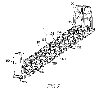
FIG. 2 illustrates a module including side plates for a spiral conveyor belt
according
to an embodiment of the present invention;
FIG. 3 is an outside view of an outer portion of the spiral conveyor belt of
FIG. 1;
FIG. 4 is an inside view of the outer portion of FIG. 3;
FIG. 5 is an outside view of an inner portion of the spiral conveyor belt of
FIG. 1;
FIG. 6 is an inner view of the inner portion of FIG. 5;
FIG. 7A is an inside view of an outer side plate suitable for coupling to a
conveyor
belt module;
FIG. 7B is an outer view of the outer side plate of FIG. 7A;
FIG. 8A is an outer view of an inner side plate suitable for coupling to a
conveyor
belt module;
FIG. 8B is an inner view of the inner side plate of FIG. 8A;
FIG. 9 shows a side plate for a conveyor belt that includes openable and
closeable
openings;
FIG. 10 is a top view showing airflow in a spiral conveyor belt system
employing an
openable and closeable side plate;
FIG. 11A is an inner view of an outer portion of a conveyor belt including
open side
plates with air foil members for adding turbulence to the air flowing through
the side plates;
FIG. 11B is a front view of the conveyor belt of FIG. 11A.
FIG. 12 is a close-up view of a portion of a self-stacking conveyor belt
including a
locking mechanism for locking two tiers together;
FIG. 13 is a close-up view of a portion of a self-stacking conveyor belt
including a
hold-down;
FIG. 14 is a side view of a self-stacking spiral conveyor belt including
another type of
hold-down;
FIG. 15A is a cross-sectional isometric view of a self-stacking spiral
conveyor belt
including a guide to prevent destacking of the belt; and
FIG. 15B is a cross-sectional detailed view of the self-stacking spiral
conveyor belt
including a guide as shown in FIG. 15A.
4
CA 02878690 2015-01-08
WO 2014/014827 PCT/US2013/050508
DETAILED DESCRIPTION OF THE INVENTION
A self-stacking spiral conveyor belt system including side plates configured
to
facilitate airflow is shown schematically in FIG. 1. The spiral belt conveyor
10 conveys
articles vertically along a substantially helical path. The spiral belt
conveyor includes a
conveyor belt 12 arranged in a helical stack 11, comprising tiers 13 of the
belt stacked serially
and directly on one another. The belt travels around various take-up, idle,
and feed
sprockets 22 as it makes it way from the exit at the top of the stack back to
the entrance at the
bottom. Alternatively, the belt may enter at the top and exit at the bottom of
the stack. The
spiral belt conveyor 10 may be used within a refrigerator, cooler, for
example, providing the
articles being conveyed with an extended route for cooling, or with a heating
system for
baking or heating products.
The illustrative conveyor belt 12 is constructed of a series of rows, each
comprising
one or more belt modules 14, like the belt module of FIG. 2. A row may
comprise a single
module spanning the width of the belt or a number of side-by-side modules. The
illustrative
belt module 14 includes a central portion 120 that extends longitudinally in a
direction of
belt travel from a first end 121 to a second end 122, laterally from an inner
edge 125 to an
outer edge 126 and in thickness from a top side 128 to a bottom side 129. A
first set 132 of
hinge elements is formed along the first end 121 of the module; a second set
134, along the
second end 122. Rod openings 136 in the hinge elements align to form lateral
passageways
through the first and second sets of hinge elements. The passageways admit a
hinge rod (not
shown) that connects a row of similar side-by-side modules to an adjacent row
of modules
into a conveyor belt. The first set of hinge elements 132 along a row of
modules interleaves
with the second set of hinge elements 134 of a longitudinally adjacent row to
form a hinge
with the hinge rod. The rod openings 136 through one or both of the leading
and trailing
hinge elements may be elongated in the direction of belt travel to allow the
belt to collapse at
the inside of a turn, while the outside edge expands.
The belt modules 14 are preferably injection molded out of a thermoplastic
material,
such as polyethylene, polypropylene, acetal, nylon, or a composite resin.
The belt modules may have any suitable configuration and are not limited to
the
illustrative embodiment.
Side plates 50, 80 are coupled to each side edge of the conveyor belt row. In
the
illustrative embodiment, a single module 14 spans an entire row, with side
plates 50, 80
5
CA 02878690 2015-01-08
WO 2014/014827
PCT/US2013/050508
connected to each side of the module. Alternatively, a row of the conveyor
belt may
comprise a plurality of modules arranged side-by-side, with an inner side
plate 80 coupled
to the inner side edge 125 of an inner module and an outer side plate 50
coupled to the outer
side edge 126 of an outer module. The side plates may be integrally formed
with the
module, or may be coupled to the module using screws, bolts, ultrasonic
welding, a snap-fit
connection or other suitable fastening means. The side plates facilitate
stacking of the belt in
the helical configuration, as each module rests on a side plate on a lower
tier, as shown in
FIGS. 3-6. Each side plate may releasable engage a portion of the conveyor
belt above it
and/or below it. Alternatively, a frame may be used to configure the helix,
with the side
plates providing additional support or airflow direction.
To facilitate airflow around product conveyed by the belt, each row of the
conveyor
belt includes two different side plates: an inner side plate 80 and an outer
side plate 50. In
the illustrative embodiment, the inner side plate 80 and outer side plate 50
are differently
configured from each other to facilitate airflow around the product conveyed
on the belt 12.
As shown, the outer side plate 50 includes openings for airflow, while the
inner side plate 80
is substantially solid, directing airflow along the path of the conveyor belt.
The inner side
plate 80 is also smaller than the outer side plate 50 in the direction of belt
travel.
The use of two different side plates facilitates the directing of airflow
across the
surface of the belt and a product conveyed by the belt to maximize heating or
cooling of the
product.
Referring to FIGS. 7A and 7B, the illustrative open side plate 50 includes a
central
spine 52 extending upwards and two planar portions 54,56 extending on either
side of the
spine 52 along the side edge. The lead planar portion 54 is offset from the
lag planar portion
56, so that the top bar 58 (formed by the top edge of the planar portions 54
and 56 and the
rib 52) of the side plate 50 is jagged. The lead planar portion 54 is
displaced outward of the
lag planar portion 56 in the illustrative embodiment. The planar portions are
staggered or
offset in the lateral direction so that the lead planar portion 54 of a
lagging side plate
overlaps with the lag side plate 56 portion of an immediately forward outer
side plate, as
shown in FIGS. 3-4.
Each planar portion 54 and 56 includes openings 62. The illustrative openings
are
separated by transverse beams 59 in the planar portions, but the openings may
have any
6
CA 02878690 2015-01-08
WO 2014/014827 PCT/US2013/050508
suitable size, shape and configuration. The openings may be configured to
promote airflow
and/or break up laminar airflow.
The lead planar portion includes a lower lead edge 541 that is straight and an
angled
edge 542 that angles towards the spine 52. The lag planar portion includes a
straight middle
lag edge 561 and an angled top portion 563 that angles towards the spine 52.
The lag planar
portion further includes a chamfered bottom edge 565.
The outer side plate 50 further includes a fastening mechanism for securing
the side
plate to the outer edge of a module. The illustrative fastening mechanism
includes a base 71,
including openings 72 for screws or another type of fastener. Projections 74
below the base
extend the screw openings 72 and, with another projection 75, form channels 76
for receiving
edges of a module to mount the side plate to the module. One or more of the
base
projections 74, 75 may fit into an opening or recess in the upper surface of
the module. The
illustrative side plate further includes a support 68 extending between the
base 71 and the
spine 52.
The side plate fastening mechanism further includes a bottom fastener 77,
shown in
FIG. 7B, that couples to the bottom surface of the module and receives the
screws to fasten
the side plate 50 to the module. The bottom fastener 77 forms a longitudinally-
extending
bottom channel 78 for receiving a top edge 58 of an outer side plate on a
lower tier, as shown
in FIGS. 3-4. The bottom channel 78 includes angled side walls that taper
inwards for
guiding the lower side plate into the channel 78. The bottom fastener 77
further includes an
outside projection 69 for engaging a drive chain driving the spiral conveyor
belt 12.
The bottom fastener 77 may be integrally molded with the module, or a separate
piece that is attached to the module 14 through any suitable means known in
the art. In one
embodiment, the bottom fastener 77 is integrally formed with the module and
the upper
portion of the outer side plate is coupled through a fastening mechanism.
FIGS. 8A and 8B illustrate an embodiment of a solid side plate 80 suitable for
use in a
self-stacking spiral conveyor belt. The illustrative solid side plate 80
comprises two parallel,
overlapping solid planar portions 84, 86, which overlap to create a central
spine 87. The
opposed planar portions 84, 86 extend forwardly and rearwardly from the spine
87 along the
direction of travel of the conveyor belt. The planar portions are staggered or
offset in the
lateral direction so that the lead planar portion 84 of a first side plate
overlaps with the lag
side plate 86 portion of an immediately forward inner side plate, as shown in
FIGS. 5-6.
7
CA 02878690 2015-01-08
WO 2014/014827 PCT/US2013/050508
The lead planar portion 84, which is inset from the lag planar portion 86,
includes a
lower lead edge 841 that is straight and an upper lead edge 842 that is angled
forward, away
from the spine 87. The lead planar portion 84 further includes a lower lag
edge 843 that is
straight and an upper lag edge 844 that is angled. The upper lag edge 844 may
be non-
parallel with the upper lead edge 842, so that the top of the lead planar
portion 84 tapers
slightly inwards.
The lag planar portion 86 includes a straight lead edge 861. The lag planar
portion
further includes a lower lag edge 863 that is straight and preferably longer
than the lower
lead edge 841 of the lead planar portion 84 and an angled upper lag edge 864
that is parallel
to the upper lead edge 842 of the lead planar portion 84. The lag planar
portion also extends
below the lead planar portion, forming a projection 89, shown in FIG. 8A, for
engaging a
drive chain.
The solid side plate 80 further includes a fastening mechanism, including a
base 91
extending from the inner side of the lead planar portion 84. The base includes
openings 92
for screws or another attachment means, as well as a support beam 98.
A separate lower fastening mechanism for the solid side plate 80 fits into an
opening
of the module and receives the screws that pass through the base 91. The lower
fastening
mechanism 97 for the side plate, shown in FIG. 5, includes a projection 98 for
guiding the
upper edge of an inner side plate on a lower tier in the stack. The lower
fastening
mechanism 97 may be integrally molded with the module, or a separate piece
that is
attached to the module 14 through any suitable means known in the art. In one
embodiment,
the lower mechanism is integrally formed with the module and the upper portion
of the
outer side plate is coupled through a fastening mechanism.
The use of an open outer side plate and a closed inner side plate promotes
airflow
around a product being conveyed. The solid side plate 80 directs air into the
center of the
belt.
In another embodiment, one or both of the open side plate 50 and solid side
plate 80,
or the fastening mechanisms for the side plates, may be integrally molded or
otherwise
formed with the module or molded directly onto the belt module. For example,
the bottom
guide tab may be molded directly to the conveyor belt module, and the top
portion of the
side plate may be added later, using any suitable fastening mechanism, such as
screws,
bolts, welding, and so on.
8
CA 02878690 2015-01-08
WO 2014/014827 PCT/US2013/050508
The side plates may be removable, to allow repairs to a broken side plate
within a
stack, or non-removable.
In one embodiment, a side plate may be molded from a different material than
the
conveyor belt module to maximize strength of the side plate in the vertical
direction, while
the belt has properties to maximize strength in the beam width direction. For
example, belt
modules can be acetal, but side plates can be a different material, such as
composite plastic
or thermoset to make them super strong.
According to another embodiment of the invention, shown in FIG. 9, a side
plate may
be openable and closeable to further facilitate airflow. The illustrative self-
venting side plate
200 includes a base 201, a planar portion 210, which may comprise a plurality
of offset,
overlapping planar portions, and openings 220 that may be selectively opened
and closed
using a valve or other suitable means. The side plate 200 has the ability to
open, to allow air
to enter the stack, and then close to contain that air while the belt is
traveling around other
parts of the spiral. The side plate 200 can then re-open on the opposite side
of the unit to
allow the air to exit the system.
Figure 10 show the airflow path that a self-venting side plate can achieve.
The inner
side plate 280 in the center of a spiral 290 is solid, as described above, so
little or no air can
flow through it. In an air entry zone 300, the outer side plates 200 open to
allow air to enter
the stack. Once the stack has rotated out of this air entry zone, the outer
side plates 200 close
and air will be forced to continue around the curved path of the spiral. On
the opposite side,
in the air exit zone 320, the outer side plates 200 re-open, allowing air to
exit the stack and be
re-circulated back to cooling coils.
The adjustable side plate 200 can have any suitable configuration. For
example, the
illustrative side plate 200 includes one or more valves, such as saloon-door
type flaps 266,
which selectively open and close the openings 220. When the belt is in the air
entry zone 300,
the flaps can open up to allow air into the system. When the system rotates
out of this air
entry zone, the flaps close to contain the air. When the system rotates to
where the outer side
plates are in the air exit zone 320, the flaps reopen to allow for air to exit
the stack 290.
Any suitable actuator may be used to open and close the side plate. For
example, in
one embodiment air pressure may be used. Ducted air can be directed at the
side plate in the
air entry section, causing the side plate to open up for air entry. In another
embodiment, the
side plate may be spring loaded to close the side plate in a default position.
When the belt
9
CA 02878690 2015-01-08
WO 2014/014827 PCT/US2013/050508
rotated out of the air entry zone, the valves may spring closed. On the air
exit side, a cam or
magnetic system could force the side plate into their open position allowing
the air to exit.
When the belt rotates out of this section, the openings would then be re-
closed.
The conveyor belt may also include other means for improving airflow around a
product. For example, the side plates may include baffling to break up laminar
airflow and
add turbulence to the air.
The open side plate may include a mechanism for inducing turbulence in air
flowing
through the side plate, promoting cooling. FIGS. 11A and 11B show a portion of
a conveyor
belt 400 including an open side plate 450 having an air foil cross member 460
for adding
turbulence to the air. The open side plate 450 is coupled to or integral with
an outer side
edge of a conveyor belt module. The open side plate 450 includes offset, open
planar
portions 545, 456 and a central spine 452. An air foil cross member 460
extends across the
openings 462 in the planar portions to direct air flow through the openings.
As indicated by
the arrows, the air foil cross member 460 pushes the air down and stirs the
air to make it
turbulent. Alternatively, the air foil cross member forces the air up to make
it turbulent.
In one embodiment, the air foil cross members alternate in orientation, so
that one
row of the conveyor belt pushes air up, while the next row pushes air down to
increase
turbulence.
The air foil cross member may have any suitable shape for directing air.
Helical
shaped structures on the air foil cross members may be added to increase or
decrease the
turbulence of the air.
The side plates facilitate stacking of the belt in the helical configuration,
as each
module rests on a side plate on a lower tier. Each side plate may releasable
engage a portion
of the conveyor belt above it and/or below it. Alternatively, a frame may be
used to
configure the helix, with the side plates providing additional support or
airflow direction.
The side plates 50, 80, may be formed of or include a detectable material. The
detectable material enables the side plate to be easily found in case of
breakage. In one
embodiment, a detection system detects the absence of a side plate in the belt
using, for
example, x-rays, metal detection or another suitable means, and stops the
running of the belt
until the missing side plate is replaced, fixed or found. Examples of suitable
materials
compatible with known detection systems, such as metal detection systems and x-
ray
detection systems include, but are not limited to the DELRIN FG400MTD BLA079
acetal
CA 02878690 2015-01-08
WO 2014/014827 PCT/US2013/050508
resin available from E.I. du Pont de Nemours and Company of Wilmington, DE or
the
DELRIN FG400XRD N010 acetal resin available from E.I. du Pont de Nemours and
Company of Wilmington, DE.
In addition, or alternatively, the side plates 50, 80 and-or the belt modules
14 may be
formed of or include a low thermal expansion material. Examples of suitable
low thermal
expansion material include, but are not limited to injected molded plastics,
such as fiber-
filled plastics, a polyphenylene sulfides, liquid crystal polymers and others
known in the art,
as well as a thermoset or non plastic material, such as metal or a carbon
fiber-type laminate.
An example of a suitable polyphenylene sulfide is TECHTRON 1000 polyphenylene
sulfide
available from Quadrant AG. An example of a suitable liquid crystal polymer is
the XYDAR
liquid crystal polymer material available from Solvay Advanced Polymers USA
LLC of
Alpharetta, GA. The use of a low thermal expansion plastic material for the
side plates 50, 80
mitigates the effects of changes in temperature, by preventing or reducing
thermal
expansion and contraction as the belt modules move from a warm zone to colder
or frozen
temperature zones.
According to another embodiment of the invention, a mechanical device for
preventing de-stacking of the belt may be used.
For example, referring to FIG. 12, a side plate 500 may include a locking
mechanism
for locking stacked tiers together. In the illustrative embodiment, the outer
side edge of a
belt module 140 includes a recess 780 in a bottom surface for engaging the top
of the side
plate 500 below. The side plate 500 includes a tab 501 for engaging the recess
780. The
illustrative tab 501 extends substantially perpendicular to the body of the
side plate 500. The
recess 780 includes a main portion and a nook 781 for receiving the leg of the
tab 501. The
recess 780 also includes tapering side surfaces 782, 783 for guiding the tab
into the recess.
Engagement of the leg is caused by pushing from a first side of the module, to
lock the tab in
the nook 781. Disengagment is caused by pushing from the second side of the
module to
release the tab from the nook 781.
In another embodiment of the invention, shown in FIG. 13, the side plate 510
or belt
module 514 may include a hold down tab 580 that engages a belt holder 600. The
belt holder
engages the hold down tab 580 to pull the belt out, preventing de-stacking.
The illustrative
hold down tab 580 includes a base 581 extending outwards from the module 514
and a leg
582 extending perpendicular to the base 581.
11
CA 02878690 2015-01-08
WO 2014/014827 PCT/US2013/050508
In another embodiment of the invention, shown in FIG. 14, a hold down 800 may
push on the top tier of the stack 11 and create a force to prevent de-stacking
of the belt. The
hold down may comprise a shoe 810, weight or other device in contact with the
top tier of
the stack. The hold down applies pressure to the top few tiers of belting to
keep them from
flipping up or de-stacking. The hold down 800 may press on top of the side
plates 50 or on
edge tabs connected to the modules.
Referring to FIGS. 15A and 15B, a self-stacking spiral conveyor belt 912 has
side
plates 950 and 980 and may include a guide, such as a top ring 900, to prevent
de-stacking.
The illustrative top ring 900 is an inner ring disposed on the inside of the
stack to keep the
stack stable if the stack starts to lean. The illustrative ring 900 is as tall
as several of the tiers
913 of the stack. For example, in an illustrative embodiment, a top portion
900a of the ring is
about eight inches in height. A central portion 900b of the ring 900 is
between about six and
about eight inches in height. The ring 900 tapers at the bottom 900c. As the
temperature
decreases and the belt gets cold, the belt may tend to shrink. The top ring
900 or other guide
stretches the shrunken belt back to the original diameter. The taper at the
bottom 900c
allows the belt to fully engage the ring. The weight of the belt sitting on
top holds the belt
down in a horizontal position as it engages the top ring and stretches to the
larger diameter.
In one embodiment of the invention, the top ring may be moveable.
Sensors may detect compression of the stack. Feedback from the sensors can be
used
to move guides in and out to prevent de-stacking.
In another embodiment of the invention, the turn ratio of the belt is matched
to that
of the first tier. This would keep the belt from collapsing any further when
the temperature
in the surrounding environment drops.
To prevent or limit destacking, the rate of temperature change may be slowed.
Slow
cooling of the belt may help limit or prevent destacking.
Although the invention has been described in detail with reference to a few
exemplary versions, other versions are possible. The scope of the claims is
not meant to be
limited to the versions described in detail.
What is claimed is:
12