Note: Descriptions are shown in the official language in which they were submitted.
CA 02878853 2015-01-09
WO 2014/014836 PCT/US2013/050541
TITLE: MULTI-PLY PUCKERED FILMS FORMED BY DISCONTINUOUS
LAMINATION OF FILMS HAVING DIFFERENT REBOUND RATIOS
BACKGROUND OF THE INVENTION
The Field of the Invention
[0001] The
present invention relates generally to thermoplastic films.
Specifically, the invention relates to multi-ply thermoplastic films with
increased loft
and to methods of manufacturing thermoplastic films to increase the loft
thereof.
Background and Relevant Art
[0002]
Thermoplastic films are a common component in various commercial
and consumer products. For example, grocery bags, trash bags, sacks, and
packaging
materials are products that are commonly made from thermoplastic films.
Additionally, feminine hygiene products, baby diapers, adult incontinence
products,
and many other products include thermoplastic films to one extent or another.
[0003] The cost
to produce products including thermoplastic film is directly
related to the cost of the thermoplastic film. Recently the cost of
thermoplastic
materials has risen. In
response, many manufacturers attempt to control
manufacturing costs by decreasing the amount of thermoplastic material in a
given
product. One way manufacturers may attempt to reduce production costs is to
use
thinner films or stretch the thermoplastic films, thereby increasing surface
area and
reducing the amount of thermoplastic film needed to produce a product of a
given
size. These thin films can be manufactured by extruding thinner films or by
cold
formation stretching films after they are extruded. Unfortunately, stretched
or
otherwise produced thinner thermoplastic films can have undesirable
properties. For
example, thinner thermoplastic films can are typically more transparent or
translucent
and can have reduced physical properties. Additionally, consumers commonly
- /-
CA 02878853 2015-01-09
WO 2014/014836 PCT/US2013/050541
associate thinner looking films with weakness. Such consumers may feel that
they are
receiving less value for their money when purchasing products with thinner
films; and
thus, may be dissuaded from purchasing thinner thermoplastic films.
Accordingly,
there is a need to create thinner films which have good physical properties
and have
the appearance of thicker, more expensive films.
BRIEF SUMMARY OF THE INVENTION
[0004]
Implementations of the present invention solve one or more problems
in the art with apparatus and methods for creating multi-ply, puckered
thermoplastic
films. In particular, one or more implementations of the present invention
include
cold formation stretching one or more film plies and then non-continuously
laminating two or more film plies together. Upon
releasing the multi-ply
thermoplastic film, differences in the rebound ratio of the film plies can
cause one or
more of the plies to pucker between lamination points thereby increasing the
gauge or
loft of the film. Additionally, one or more implementations include multi-ply,
puckered thermoplastic films with increased loft.
[0005] For
example, an implementation of a method for forming a multi-ply,
puckered thermoplastic film with increased loft can involve providing a first
thermoplastic film with a first rebound ratio and providing a second
thermoplastic
film with a second rebound ratio. The second rebound ratio can differ from the
first
rebound ratio. The rebound ratios of the first and second thermoplastic films
might
differ if one has undergone a different type or degree of cold formation
stretching or if
the first or second thermoplastic films are of different materials or
different
thicknesses. The method can also involve non-continuously laminating the first
and
the second thermoplastic films together. The method can then involve releasing
one
or more of the first and the second thermoplastic films. The first
thermoplastic film
can rebound more than the second thermoplastic film upon releasing of the
films
thereby causing puckering of the first thermoplastic film.
[0006]
Additionally, an implementation of a multi-ply, puckered
thermoplastic film formed from first and second thermoplastic films can
comprise a
first thermoplastic film ply with a first gauge and a second thermoplastic
film ply with
a second gauge. A plurality of non-continuous laminated areas can bond the
first and
- _
CA 02878853 2015-01-09
WO 2014/014836 PCT/US2013/050541
the second thermoplastic film plies together. The film can also include a
plurality of
puckers in one or more of the first and the second thermoplastic film plies.
The
puckers can be located between and maintained by adjacent laminated areas. A
loft of
the puckers can be greater than a sum of the first gauge and the second gauge.
[0007] In addition to the forgoing, a multi-ply, puckered thermoplastic
bag
can comprise a first ply of thermoplastic material. The first ply can include
first and
second side walls joined along a bottom edge, a first side edge, and an
opposing
second side edge. The bag can also include a second ply of thermoplastic
material
positioned inside the first ply. The second ply can include first and second
side walls
joined along a bottom edge, a first side edge, and an opposing second side
edge. A
plurality of non-continuous laminated areas can bond the first ply to the
second ply.
Additionally, the bag can include a plurality of non-continuous puckers in the
first
ply.
[0008] Additional features and advantages of exemplary embodiments of
the
present invention will be set forth in the description which follows, and in
part will be
obvious from the description, or may be learned by the practice of such
exemplary
embodiments. The features and advantages of such embodiments may be realized
and
obtained by means of the instruments and combinations particularly pointed out
in the
appended claims. These and other features will become more fully apparent from
the
following description and appended claims, or may be learned by the practice
of such
exemplary embodiments as set forth hereinafter.
BRIEF DESCRIPTION OF THE DRAWINGS
[0009] In order to describe the manner in which the above-recited and
other
advantages and features of the invention can be obtained, a more particular
description of the invention briefly described above will be rendered by
reference to
specific embodiments thereof which are illustrated in the appended drawings.
It
should be noted that the figures are not drawn to scale, and that elements of
similar
structure or function are generally represented by like reference numerals for
illustrative purposes throughout the figures. Understanding that these
drawings depict
only typical embodiments of the invention and are not therefore to be
considered to be
- 3 -
CA 02878853 2015-01-09
WO 2014/014836 PCT/US2013/050541
limiting of its scope, the invention will be described and explained with
additional
specificity and detail through the use of the accompanying drawings in which:
[0010] Fig. lA illustrates a side, cross-sectional view of two
thermoplastic
films prior to stretching in accordance with one or more implementations of
the
present invention;
[0011] Fig. 1B illustrates a side, cross-sectional view of two
thermoplastic
films stretched and non-continuously laminated together in accordance with one
or
more implementations of the present invention;
[0012] Fig. IC illustrates a side, cross-sectional view of a multi-ply,
puckered
thermoplastic film with increased loft in accordance with one or more
implementations of the present invention;
[0013] Fig. 2A illustrates a side, cross-sectional view of two
thermoplastic
films stretched and laminated together in accordance with one or more
implementations of the present invention;
[0014] Fig. 2B illustrates a perspective view of two thermoplastic
films of Fig.
3A stretched and partially non-continuously laminated together in accordance
with
one or more implementations of the present invention;
[0015] Fig. 3A illustrates a side, cross-sectional view of two
thermoplastic
films stretched and laminated together in accordance with one or more
implementations of the present invention;
[0016] Fig. 3B illustrates a perspective view of two thermoplastic
films of Fig.
3A stretched and non-continuously laminated together in accordance with one or
more implementations of the present invention;
[0017] Fig. 4 illustrates a top view of a multi-ply, puckered
thermoplastic film
with increased loft formed using MD ring rolling in accordance with one or
more
implementations of the present invention;
[0018] Fig. 5 illustrates a perspective view of a bag having a multi-
ply,
puckered thermoplastic film with increased loft formed using TD ring rolling
in
accordance with one or more implementations of the present invention;
- 4 -
CA 02878853 2015-01-09
WO 2014/014836 PCT/US2013/050541
[0019] Fig. 6A illustrates a perspective view of a bag incorporating a
multi-
ply, puckered thermoplastic film similar to the film shown in Fig. 6 in
accordance
with one or more implementations of the present invention;
[0020] Fig. 6B illustrates a perspective, cross-sectional view of the
laminated
areas of the multi-ply film of Fig. 6A;
[0021] Fig. 7 illustrates a schematic diagram of a bag manufacturing
process
in accordance with one or more implementations of the present invention; and
[0022] Fig. 8 illustrates a schematic diagram of another bag
manufacturing
process in accordance with one or more implementations of the present
invention.
DETAILED DESCRIPTION OF THE PREFERRED EMBODIMENTS
[0023] One or more implementations of the present invention include
apparatus and methods for creating multi-ply, puckered thermoplastic films. In
particular, one or more implementations of the present invention include cold
folination stretching one or more film plies and then non-continuously
laminating two
or more film plies together. Upon releasing the multi-ply thermoplastic film,
differences in the rebound ratio of the film plies can cause one or more of
the plies to
pucker between lamination points thereby increasing the gauge or loft of the
film.
Additionally, one or more implementations include multi-ply, puckered
thermoplastic
films with increased loft.
[0024] Indeed, one or more implementations of the present invention can
provide thermoplastic films, and products made there from, with increased loft
created by one or more puckers. The increased loft created by one or more
puckers
can connote strength to a consumer. Additionally, the puckers can provide the
film
with increased softness and a desirable look and feel.
[0025] Furthermore, implementations of the present invention allow for
tailoring (e.g., increasing) of the loft of a film independent of the basis
weight
(amount of raw material) of the film. Thus, one or more implementations can
provide
films with increased loft despite a reduction in thermoplastic material. As
such, one
or more implementations can reduce the material needed to produce a product
while
maintaining or increasing the loft of the film.
- 5 -
CA 02878853 2015-01-09
WO 2014/014836 PCT/US2013/050541
[0026] Additionally, consumers may associate thinner films (e.g., films
with
decreased basis weight) with decreased strength. Indeed, consumers may feel
that
they are receiving less value for their money when purchasing thermoplastic
film
products with thinner gauges. One will appreciate in light of the disclosure
herein
that a consumer may not readily detect that one or more puckered films of the
present
invention has a reduced basis weight. In particular, by increasing the loft of
thinner
films, the consumer may perceive the puckered film as being thicker and/or
having
increased strength.
[0027] In addition to the foregoing, one or more implementations
provide
thermoplastic films with increased loft that consumers can associate with
improved
properties. For example, the puckered regions can indicate that those regions
have
undergone a transformation to impart a desirable characteristic to that region
(e.g.,
increased strength or thicker feel). Thus, the puckered regions can serve to
notify a
consumer that the thermoplastic film has been processed to improve the film.
[0028] As explained in greater detail below, the loft of a
thermoplastic film
can be based, at least in part, on the thermoplastic material of the film
being stretched.
As an initial matter, the thermoplastic material of the films of one or more
implementations can include, but are not limited to, thermoplastic
polyolefins,
including polyethylene and copolymers thereof and polypropylene and copolymers
thereof. The olefin based polymers can include the most common ethylene or
propylene based polymers such as polyethylene, polypropylene, and copolymers
such
as ethylene vinylacetate (EVA), ethylene methyl acrylate (EMA) and ethylene
acrylic
acid (EAA), or blends of such polyolefins.
[0029] Other examples of polymers suitable for use as films in
accordance
with the present invention include elastomeric polymers. Suitable elastomeric
polymers may also be biodegradable or environmentally degradable. Suitable
elastomeric polymers for the film include poly(ethylene-butene), poly(ethylene-
hexene), poly(ethylene-octene), poly(ethylene-propylene), poly(styrene-
butadiene-
styrene), poly(styrene-isoprene-styrene), poly(styrene-ethylene-butylene-
styrene),
poly(ester-ether), poly(ether-amide), poly(ethylene-vinylacetate),
poly(ethylene-
- 6 -
CA 02878853 2015-01-09
WO 2014/014836 PCT/US2013/050541
methylacrylate), poly(ethylene-acrylic acid), poly(ethylene butylacrylatc),
polyurethane, poly(ethylene-propylene-dienc), ethylene-propylene rubber.
[0030] In at least one implementation of the present invention, the
film can
include linear low density polyethylene. The term "linear low density
polyethylene"
(LLDPE) as used herein is defined to mean a copolymer of ethylene and a minor
amount of an alkene containing 4 to 10 carbon atoms, having a density of from
about
0.910 to about 0.926, and a melt index (MI) of from about 0.5 to about 10. For
example, some implementations of the present invention can use an octene
comonomer, solution phase LLDPE (MI=1.1; p=0.920). Additionally, other
implementations of the present invention can use a gas phase LLDPE, which is a
hex ene gas phase LLDPE formulated with slip/AB (MI=1.0; p=0.920). Still
further
implementations of the present invention can use a gas phase LLDPE, which is a
hexene gas phase LLDPE formulated with slip/AB (MI=1.0; p=0.926). One will
appreciate that the present invention is not limited to LLDPE, and can include
"high
density polyethylene" (HDPE), "low density polyethylene" (LDPE), and "very low
density polyethylene" (VLDPE). Indeed films made from any of the previously
mentioned thermoplastic materials or combinations thereof can be suitable for
use
with the present invention.
[0031] Indeed, implementations of the present invention can include any
flexible or pliable thermoplastic material which may be formed or drawn into a
web
or film. Furthermore, the thermoplastic materials may include a single layer
or
multiple layers. An example of multilayered films that are suitable for use
with one
or more implementations of the present invention include coextruded
multilayered
films. Examples of multi-ply films include multiple films continuously
laminated
together, and multiple films partially or discontinuously laminated together.
The
thermoplastic material may be opaque, transparent, translucent, or tinted.
Furthermore, the thermoplastic material may be gas permeable or impermeable.
[0032] As used herein, the term "flexible" refers to materials that are
capable
of being flexed or bent, especially repeatedly, such that they are pliant and
yieldable
in response to externally applied forces. Accordingly, "flexible" is
substantially
opposite in meaning to the terms inflexible, rigid, or unyielding. Materials
and
- 7 -
structures that are flexible, therefore, may be altered in shape and structure
to
accommodate external forces and to conform to the shape of objects brought
into contact
with them without losing their integrity. In accordance with further prior art
materials,
web materials are provided which exhibit an "elastic-like" behavior in the
direction of
applied strain without the use of added traditional elastic. As used herein,
the term
"elastic-like" describes the behavior of web materials which when subjected to
an applied
strain, the web materials extend in the direction of applied strain, and when
the applied
strain is released the web materials return, to a degree, to their pre-
strained condition.
[0033] In addition to the foregoing, one will appreciate in light
of the disclosure
herein that manufacturers may form the films or webs to be used with the
present
invention using a wide variety of techniques. For example, a manufacturer can
form the
films using conventional flat or cast extrusion or coextrusion to produce
monolayer,
bilayer, or multilayer films. Alternatively, a manufacturer can form the films
using
suitable processes, such as, a blown film process to produce monolayer,
bilayer, or
multilayer films. If desired for a given end use, the manufacturer can orient
the films by
trapped bubble, tenterframe, or other suitable process. Additionally, the
manufacturer can
optionally anneal the films thereafter.
[0034] In one or more implementations, the films of the present
invention are
blown film, or cast film. Blown film and cast film is formed by extrusion. The
extruder
used can be a conventional one using a die, which will provide the desired
gauge. Some
useful extruders are described in U.S. Pat. Nos. 4,814,135; 4,857,600;
5,076,988;
5,153,382. Examples of various extruders, which can be used in producing the
films to be
used with the present invention, can be a single screw type modified with a
blown film
die, an air ring, and continuous take off equipment.
[0035] In a blown film process, the die can be an upright cylinder
with an
annular opening. Rollers can pull molten plastic upward away from the die. An
air-
ring can cool the film as the film travels upwards. An air outlet can force
compressed
air into the center of the extruded annular profile, creating a bubble. The
air can
expand the extruded circular cross section by a multiple of the die diameter.
This
- 8 -
CA 2878853 2018-07-16
CA 02878853 2015-01-09
WO 2014/014836 PCT/US2013/050541
ratio is called the -blow-up ratio." When using a blown film process, the
manufacturer can collapse the film to double the plies of the film.
Alternatively, the
manufacturer can cut and fold the film, or cut and leave the film unfolded.
[0036] In one implementation, the multi-ply, puckered thermoplastic
film
comprises a first ply of thermoplastic material having a first ply maximum
gauge,
wherein the first ply has been cold formation stretched to form alternating
thick areas
of un-stretched material and thin areas of stretched material; a second ply of
thermoplastic material having a second ply maximum gauge and adjacent to the
first
ply, wherein the second ply has not been cold formation stretched; a plurality
of non-
continuous laminated areas bonding the first ply to the second ply wherein the
laminated areas between the first ply and the second ply are formed with the
first ply
in the stretched condition; and a plurality of puckers in the second
thermoplastic ply,
the puckers being located between and maintained by adjacent laminated areas
and
the puckers having a height of at least 1.25 times the sum of the first ply
maximum
gauge and the second ply maximum gauge. Cold formation stretching can decrease
the gauge and create greater orientation and give improved properties.
[0037] In another implementation, the multi-ply, puckered thermoplastic
film
comprises a first ply of thermoplastic material having a first ply maximum
gauge,
wherein the first ply has been cold formation stretched by MD ring rolling to
form
alternating thick layers of un-stretched material and thin areas of stretched
material; a
second ply of thermoplastic material having a second ply maximum gauge and
adjacent to the first ply; a plurality of non-continuous laminated areas
bonding thick
areas of the first ply to the second ply wherein the laminated areas are
formed with the
first ply in the stretched condition; and a plurality of puckers in the second
thermoplastic ply, the puckers being located between and maintained by
adjacent
laminated areas and the puckers having a height of at least 1.25 times the sum
of the
first ply maximum gauge and the second ply maximum gauge.
[0038] In another implementation, the multi-ply, puckered thermoplastic
film
formed from first and second thermoplastic films, comprises a first
thermoplastic film
ply with a first gauge; a second thermoplastic film ply with a second gauge; a
plurality of non-continuous laminated areas that bond the first and the second
- 9 -
CA 02878853 2015-01-09
WO 2014/014836 PCT/US2013/050541
thermoplastic film plies together wherein the laminated areas are formed with
the first
ply in the stretched condition; and a plurality of puckers in one or more of
the first
and the second thermoplastic film plies, the puckers being located between and
maintained by adjacent laminated areas; wherein a loft of the puckers is
greater than a
sum of the first gauge and the second gauge.
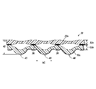
[0039] Referring now to the Figures, Figs. IA-1C illustrate one
implementation of a process of stretching, non-continuously laminating, and
releasing
a multi-ply thermoplastic film to create puckers in the film. As previously
mentioned
the puckers can increase the loft of the film. For example, in Fig. 1A, 30a
represents
a film that has been cold formation stretched by MD ring rolling at a small
strain and
30b represents a film that has been cold formation stretched MD ring rolling
at a
larger strain. The film 30a has alternating thick areas 31a and thin areas 31b
and a
maximum gauge 32a. The film 30b has alternating thick areas 31c, 31d and thin
areas
31e, 31f and a maximum gauge 32b. The cold formation stretched MD ring rolled
plies 30a, 30b are flexible film plies of thick and thin areas as opposed to
rigid fluted
structures, which are not suitable for to produce the puckered laminates of
the
invention.
[0040] In particular, Fig. lA illustrates a first thermoplastic film
30a with a
first starting gauge 32a and a second thermoplastic film 30b with a second
starting
gauge 32b. Together the first and second thermoplastic films 30a, 30b can have
an
initial loft 32a plus 32b. As used herein, the term "loft" refers to the
largest distance
between the outer major surfaces of a film. Thus, the combined loft (32a plus
32b) of
the first and second thermoplastic films 30a, 30b is equal to the sum of the
starting
gauge 32a and the starting gauge 32b.
[0041] In one or more implementations, prior to stretching and
laminating, the
starting gauges 32a, 32b need not be consistent or uniform throughout the
entirety of
the first and second thermoplastic films 30a, 30b. Thus, the starting gauges
32a, 32b
can vary along one or both dimensions of the film due to cold formation
stretching,
intentional product design, manufacturing defects, tolerances, or other
processing
inconsistencies. The films of one or more implementations of the present
invention
can have a starting gauge between about 0.1 mils to about 20 mils, suitably
from
- io -
CA 02878853 2015-01-09
WO 2014/014836 PCT/US2013/050541
about 0.2 mils to about 4 mils, suitably in the range of about 0.3 mils to
about 2 mils,
suitably from about 0.6 mils to about 1.25 mils, suitably from about 0.9 mils
to about
1.1 mils, suitably from about 0.3 mils to about 0.7 mils, and suitably from
about 0.4
mils and about 0.6 mils.
[0042] The individual films or plies (e.g., first and second
thermoplastic films
30a, 30b) may each themselves comprise a plurality of film layers. Such film
layers
may be joined by, for example, co-extrusion, spread coating, extrusion
coating, and
combinations thereof. In particular, one or more of the first and second
thermoplastic
films 30a, 30b can comprise two, three, four, or more co-extruded, or
otherwise
bonded, layers. For ease in description, the first and second thermoplastic
films 30a,
30b are described and shown herein as single film layers. One will appreciate,
however, that the present invention is not so limited, and the first and
second
thermoplastic films 30a, 30b can each include one, two, three, or more layers.
[0043] Additionally, the present invention contemplates using more than
two
separate thermoplastic films or plies to create multi-ply, puckered
thermoplastic films
with increased loft. For example, multi-ply, puckered thermoplastic films of
one or
more implementations can include two, three, or more separate films or plies.
Furthermore, one or more of the thermoplastic films or plies can include
puckers as
explained in greater detail below. For ease in description, multi-ply,
puckered
thermoplastic films including two film plies (i.e., first and second
thermoplastic films
30a, 30b) are described and shown herein. One will appreciate, however, that
the
present invention is not so limited, and more than two film plies can be
stretched,
non-continuously laminated, and released to form multi-ply, puckered
thermoplastic
films.
[0044] As alluded to earlier, the first thermoplastic film 30a can have
a first
rebound ratio and the second thermoplastic film 30b can have a second rebound
ratio,
differing from the first rebound ratio. As used herein, the term "rebound
ratio" refers
to how much a film will rebound or snapback after stretching and releasing. In
particular, the term "rebound ratio" refers to the ratio of a dimension of the
film after
stretching and releasing of the film compared to the dimension after
stretching. For
-11 -
CA 02878853 2015-01-09
WO 2014/014836 PCT/US2013/050541
example, a film that is stretched to a length of 1.25 meters and released, and
rebounds,
upon release, to a length of about 1.0 meter has a rebound ratio of 0.80
(1.0/1.25).
[0045] One will appreciate in light of the disclosure herein that
various factors
influence the rebound ratio of a thermoplastic film. For example, the
elasticity of a
thermoplastic film can influence the rebound ratio of the thermoplastic film.
Additionally, the amount or degree of stretching the thermoplastic film
undergoes can
influence the rebound ratio of the thermoplastic film. Thus, two films of the
same
thermoplastic material can have different rebound ratios if they are stretched
to
differing degrees. Similarly, two films of different thermoplastic material
can have
different rebound ratios when stretched to the same degree or differing
degrees,
depending upon their material properties.
[0046] In any event, the first thermoplastic film 30a can have a first
rebound
ratio and the second thermoplastic film 301.) can have a second rebound ratio,
differing
from the first rebound ratio. A difference in material properties of the first
and second
thermoplastic films 30a, 30b can provide the difference in rebound ratios.
Alternatively, or additionally, a difference in the degree of stretching which
the first
and second thermoplastic films 30a, 30b undergo can provide the difference in
rebound ratios.
[0047] As previously mentioned, one or more implementations include
stretching one or more of the first and second thermoplastic films 30a, 30b.
The two
films 30a and 30b can be laminated under stretching tension by MD ring rolling
together to give a cold formation stretched film laminate 34 shown in Fig. 1B,
where
film 30a stretches to a greater extent during lamination than film 30b to give
laminated areas 36.
[0048] For example, Fig. 1B illustrates the first thermoplastic film
30a
stretched to increase its length. A manufacturer can also optionally stretch
the second
thermoplastic film 30b to the same or differing degree as the first
thermoplastic film
30a. Alternatively, the second thermoplastic film 30b can remain unstretched
so long
as the first and second thermoplastic films 30a, 30b have differing rebound
ratios.
One will appreciate in light of the disclosure herein that any of MDO,
tentering, MD
ring rolling, TD ring rolling, diagonal direction ("DD") ring rolling, a
structural
- 12 -
CA 02878853 2015-01-09
WO 2014/014836 PCT/US2013/050541
elastic like film process ("SELFing"), embossing, other stretching methods, or
combinations thereof may be used to stretch one or more of the first and
second
thermoplastic films 30a, 30b.
[0049] After
stretching one or more of the first and second thermoplastic films
30a, 30b, a manufacturer can non-continuously laminate the first and second
thermoplastic films 30a, 30b together. As used herein, the terms "lamination,"
"laminate," and "laminated film," refer to the process, and resulting product,
made by
bonding together two or more plies of film or other materials. The term
"bonding,"
when used in reference to bonding of multiple plies of a multi-ply film, may
be used
interchangeably with "lamination" of the plies. According to methods of one or
more
implementations of the present invention, adjacent plies of a multi-ply film
are non-
continuously laminated or bonded to one another.
[0050] Non-
continuous lamination includes discontinuous lamination and
partially discontinuous lamination. Discontinuous lamination refers to
lamination of
two or more plies where the lamination is not continuous in the machine
direction and
not continuous in the transverse direction. More
particularly, discontinuous
lamination refers to lamination of two or more plies with repeating bonded
patterns
broken up by repeating un-bonded areas in both the machine direction and the
transverse direction of the film.
[0051] Partially
discontinuous lamination refers to lamination of two or more
plies where the lamination is substantially continuous in the machine
direction or in
the transverse direction, but not continuous in the other of the machine
direction or
the transverse direction. Alternately, partially discontinuous lamination
refers to
lamination of two or more plies where the lamination is substantially
continuous in
the width of the article but not continuous in the height of the article, or
substantially
continuous in the height of the article but not continuous in the width of the
article.
More particularly, partially discontinuous lamination refers to lamination of
two or
more plies with repeating bonded patterns broken up by repeating unbounded
areas in
either the machine direction or the transverse direction.
[0052] In order
to combine the lamination with an additional stretching
operation, it may be advantageous to laminate the two or more plies by a non-
heated
- 13 -
CA 02878853 2015-01-09
WO 2014/014836 PCT/US2013/050541
cold formation process from the group consisting of as MD ring rolling, TD
ring
rolling, SELFing or combinations thereof. The lamination step may also be
performed by an alternative process, such as adhesive lamination or heated or
non-
heated embossing. In order to preserve the orientation achieved by the prior
cold
formation stretching operations, it may be advantageous to perform the
lamination
with the two or more plies aligned in the same direction, such as the MD
direction,
rather than forming a cross-laminate or laminate where one ply is aligned at
an angle
to the other ply.
[0053] For
example, Fig. 1B illustrates the first thermoplastic film 30a
partially discontinuously bonded to the second thermoplastic film 30b by a
plurality
of laminated areas 36, where the lamination takes place after the first
thermoplastic
film 30a has been stretched to a greater degree than the second thermoplastic
film
30b. The first thermoplastic film 30a has lesser rebound ratio than the second
thermoplastic film 30b. Fig. 1B shows the thermoplastic films 30a, 30b in the
stretched and laminated condition. In particular, the laminated areas 36
extend
continuously between the first and second films 30a, 30b in the transverse
direction,
but non-continuously in the machine direction. As shown by Fig. 1B, the
laminated
areas 36 are uniformly spaced across the first and second thermoplastic films
30a,
30b. In alternative implementations, the laminated areas 36 can be regularly
or
irregularly spaced. One will
appreciate that the pattern or configuration of the
laminated areas 36 can depend upon the technique used to laminate the first
and
second thermoplastic films 30a, 30b.
[0054] A
manufacturer can use one or more suitable techniques to non-
continuously laminate the first and second thermoplastic films 30a, 30b
together. For
example, a manufacturer can use pressure without (for example MD ring rolling,
TD
ring rolling, stainable network lamination, or cold embossing), or a
combination of
heat and pressure, such as heated embossing. The combination of pressure and
heat
will normally form a stronger laminate, but will also be a more complicated
and
expensive process. Alternately, a manufacturer can use ultrasonic bonding.
Still
further, a manufacturer can use adhesives to laminate the first and second
- 14-
thermoplastic films 30a, 30b together. Treatment with a Corona discharge can
enhance
the lamination step of any of the above methods.
[0055] After lamination, the film laminate 34 is released to a
relaxed state, as in
Fig. 1C, to give laminate 38 with puckers 40, where the increased loft or
height 42 of the
puckered laminate 38 is greater than the sum of the gauges 32a, 32b of films
30a and
30b. The height 42 of the puckers 40 can be at least 1.1 times, 1.25 times,
1.5 times, 2
times, more than 2 times, 3 times, or more than 3 times the sum of gauges 32a
and 32b.
[0056] After lamination, the manufacturer can release the first and
second
thermoplastic films 30a, 30b to a relaxed state to form a multi-ply, puckered
thermoplastic film 38 as shown by Fig. 1C. Upon release, one of the first and
the second
thermoplastic films 30a, 30b can rebound more than the other of the first and
second
films 30a, 30b due to the difference in rebound ratios. For example, as shown
by Fig.
1C, the second thermoplastic film 30b can rebound more than the first
thermoplastic
film 30a. The difference in rebound, in connection with the laminated areas
36, can
cause the second thermoplastic film 30b to billow between adjacent laminated
areas 36,
thereby, creating puckers 40.
[0057] As used herein the term "pucker" refers to the billowing of a
thermoplastic film between non-continuous laminated areas such that the
thermoplastic film does not lie in a planar position between adjacent
laminated areas.
One will appreciate that a pucker, as used herein, is created by the drawing
together of
adjacent laminated areas 36 formed when a stretched film 30a is non-
continuously
laminated at laminated areas 36 to an adjacent film 30b thereby forming
puckers 40 in
the adjacent film 30b. Thus, in one or more implementations, the puckers 40
are
formed and maintained by a strain or force (e.g., laminated areas 36) external
to the
puckered film (e.g., second thermoplastic film 30b). In other words, in one or
more
implementations, a pucker is not a structure or geometry imparted or formed
into a
film that will retain its shape or geometry when the puckered film is no
longer subject
to any external strains or forces, for example, as in a corrugated or fluted
film. Thus,
in one or more implementations, puckers also differ from ribs or other
structures
imparted or formed in a film during SELFing, ring rolling, embossing, or other
similar
- 15 -
CA 2878853 2018-07-16
CA 02878853 2015-01-09
WO 2014/014836 PCT/US2013/050541
processes that retain their form when the film is no longer subject to any
strains or
externally applied forces.
[0058] Thus, the multi-ply, puckered thermoplastic film 38 can include
a first
thermoplastic film ply (first thermoplastic film 30a) and a second
thermoplastic film
ply (second thermoplastic film 30b). A plurality of non-continuous laminated
areas
36 can bond the first and the second thermoplastic film plies 30a, 30b of the
multi-
ply, puckered thermoplastic film 38 together. Furthermore, the second
thermoplastic
film ply 30b can include a plurality of puckers 40 located between and
maintained by
adjacent laminated areas 36.
[0059] The puckers 40 can increase the loft 42 of multi-ply, puckered
thermoplastic film 38 compared to the loft 32a and 32b of the first and second
thermoplastic films 30a, 30b. In particular, the loft 42 of the multi-ply,
puckered
thermoplastic film 38 can be between 1.1 and about 20 times, or between 1.1
and 200
times, or 1.1 and 500 times greater than the loft 32a plus 32b of the first
and second
thermoplastic films 30a, 30b. Suitably, the loft 42 of the multi-ply, puckered
thermoplastic film 38 is between about 1.1 and about 10 times greater than the
loft
32a plus 32b of the first and second thermoplastic films 30a, 30b. In
additional
implementations, the loft 42 of the multi-ply, puckered thermoplastic film 38
is
between about 1.25 and about 5 times greater than the loft 32a plus 32b of the
first
and second thermoplastic films 30a, 30b. In further implementations, the loft
42 of
the multi-ply, puckered thermoplastic film 38 is about 1.50, about 2, about
2.5, about
3, or about 4 times greater than the loft 32a plus 32b of the first and second
thermoplastic films 30a, 30b. In other implementations, the loft 42 of the
multi-ply,
puckered thermoplastic film 38 is about greater than 10 times, or 20 times, or
50
times, or 100 times the loft 32a plus 32b of the first and second
thermoplastic films
30a, 30b.
[0060] The increased loft 42 of the multi-ply, puckered thermoplastic
film 38
can provide the film 38 with a look and a feel of a stronger film. In
particular, the
increased loft can connote increased strength to a consumer. In addition to
the
differences in loft, the space between the first and the second thermoplastic
films 30a,
30b created by the puckers 40 can scatter light and make the multi-ply,
puckered
-16-
thermoplastic film 38 less transparent or translucent. By increasing the
opacity, the
puckers 40 can make the multi-ply, puckered thermoplastic film 38 appear
thicker.
[0061] One will appreciate in light of the disclosure herein that
the pattern of
the puckers can vary depending on the method used to stretch and/or laminate
the
thermoplastic films. For example, in Fig. 1A, 30a represents a film that has
been cold
formation stretched by MD ring rolling at a small strain and 30b represents a
film that
has been cold formation stretched MD ring rolling at a larger strain. The film
30a has
alternating thick areas 31a and thin areas 31 b and a maximum gauge 32a. The
film 30b
has alternating thick areas 31c, 31d and thin areas 31e, 31f and a maximum
gauge 32b.
The two films 30a and 30b are then laminated under tension by MD ring rolling
together
to give a stretched film laminate 34 shown in Fig 1B, where film 30a stretches
to a
greater extent during lamination than film 30b to give laminated areas 36.
After
lamination, the film laminate 34 is relaxed, as in Fig. 1C, to give laminate
38 with
puckers 40, where the increased loft or height 42 of the puckered laminate 38
is greater
than the sum of the gauges 32a, 32b of films 30a and 30b. The height 42 of the
puckers
40 can be at least 1.1 times, 1.25 times, 1.5 times, 2 times, more than 2
times, 3 times,
or more than 3 times the sum of gauges 32a and 32b.
100621 Fig. 2A illustrates a side view of a flat film ply 50
laminated to cold
formation stretched film ply 52 at laminated areas 54 to give laminated multi-
ply film
56. The film ply 52 was cold formation stretched by MD ring rolling to give
alternating
thick areas 58a and thin areas 58b. Alternately, the film ply could be cold
formation
stretched by another process such as TD ring rolling or strainable network
formation to
give thick areas and thin areas. Film ply 52 has a maximum gauge of 53 a. Film
ply 50
has a relatively constant gauge 51a and is relatively flat. The multiply film
56 has
puckers 60 with the height 62 of the puckers 60 is greater than the sum of the
gauges
51a and 53a of the film plies 50, 52. The height of the puckers can be at
least 1.1 times,
1.25 times, 1.5 times, 2 times, more than 2 times, 3 times, or more than 3
times the sum
of gauges 51a and 51b.
[0063] Fig. 2B illustrates a perspective view of a flat film ply 50
laminated to
cold formation stretched film ply 52 at laminated areas 54 to give laminated
multi-ply
film 56. The laminated areas 54 are continuous in the TD direction, but
discontinuous
-17-
CA 2878853 2018-07-16
CA 02878853 2015-01-09
WO 2014/014836 PCT/US2013/050541
in the MD direction to give partially discontinuous lamination. The lamination
areas
were formed by a cold formation process selected from the group consisting of
MD
ring rolling, TD ring rolling, and strainable network formation, or
combinations
thereof. The cold formation process may advantageously result in additional
cold
stretching. The lamination areas could also be formed by a non-cold formation
process such as embossing or adhesive bonding.
[0064] Fig. 3A illustrates a side view of a flat film ply 70 laminated
to cold
formation stretched film ply 72 at laminated areas 74 to give laminated multi-
ply film
76. The film ply 72 was cold formation stretched by MD ring rolling to give
alternating thick areas 78a and thin areas 78b. Alternately, the film ply
could be cold
formation stretched by another process such as TD ring rolling or strainable
network
formation to give thick areas and thin areas. Film ply 72 has a maximum gauge
of
73a. Film ply 70 has a relatively constant gauge 71a and is relatively flat.
The multi-
ply film 76 has puckers 80 with the height 82 of the puckers 80 is greater
than the sum
of the gauges 71a and 73a of the film plies 70, 72. The height of the puckers
can be at
least 1.1 times, 1.25 times, 1.5 times, 2 times, more than 2 times, 3 times,
or more
than 3 times the sum of gauges 71a and 71b. The lamination was formed with
both
film plies oriented in the MD direction, rather than as a cross laminate.
[0065] Fig. 3B illustrates a perspective view of a flat film ply 70
laminated to
cold formation stretched, MD ring rolled film ply 72 at laminated areas 74 to
give
laminated multi-ply film 76. The laminated areas 74 are discontinuous in the
TD
direction and discontinuous in the MD direction. The lamination areas were
formed
by a process selected from the group consisting of MD ring rolling, TD ring
rolling,
strainable network formation, embossing, adhesive bonding, or combinations
thereof.
The lamination was formed with both film plies oriented in the MD direction,
rather
than as a cross laminate.
[0066] Fig. 4 illustrates a top view of a multi-ply, puckered
thermoplastic film
90 in which the plies of the film 90 oriented in the MD direction and were
partially
discontinuously laminated together using MD ring rolling under conditions
where the
plies of the film 90 had different rebound ratios. As shown by Fig. 4, the
film 90 can
include alternating puckers 92a and laminated areas 92b. Further, either or
both of the
- 18-
CA 02878853 2015-01-09
WO 2014/014836 PCT/US2013/050541
puckers 92a and the "un-puckered" laminated areas 92b can extend along the
length
of the film in the transverse direction.
[0067] When ring rolling is used for stretching and laminating, the
pitch
(distance between adjacent teeth or ridges on the ring rolls) and the depth of
engagement ("DOE") (overlap of intermeshing teeth or ridges of the ring rolls)
can
determine the width and spacing of the puckers and/or laminated areas. By
varying
the pitch and/or DOE of the ring rolls, a manufacturer can vary the width
and/or
spacing of the puckers. Thus, a manufacturer can impart a rougher feel to a
multi-ply,
puckered thermoplastic film by increasing the frequency and/or reducing the
size of
the puckers. Alternatively, a manufacturer can impart a softer feel to a multi-
ply,
puckered thermoplastic film by decreasing the frequency and/or increasing the
size of
the puckers.
[0068] Fig. 4 further illustrates that the puckers 92a can reside about
un-
puckered laminated areas 92b. In particular, each pucker 92a can reside
between
adjacent laminated areas 92b. Additionally, the puckers 92a can have a
distinct feel
or look compared with the laminated areas 92b. In particular, the puckers 92a
can
differ from the laminated areas 92b in one or more of feel or look. For
example, the
puckers 92a can feel thicker and look more opaque than the laminated areas
92b.
[0069] The loft of the puckers of one or more implementations can vary
based
on the rebound ratio of the plies within the multi-ply, puckered thermoplastic
film.
For instance, when the multi-ply, puckered thermoplastic film contains two
film plies
with small differences in rebound ratios, the loft of the puckers may be
relatively
small. On the other hand, when the multi-ply, puckered thermoplastic film
contains
two film plies with large differences in rebound ratios, the loft of the
puckers can be
relatively large.
[0070] As mentioned previously, MD ring rolling is one exemplary method
of
stretching and/or laminating thermoplastic films to create a multi-ply,
puckered
thermoplastic film in accordance with the present invention. TD ring rolling
is
another suitable method of stretching and/or laminating thermoplastic films to
create
multi-ply, puckered thermoplastic films. For example in Fig. 5, a perspective
view of
a bag 100 from a multi-ply, puckered thermoplastic film 102 created by
orienting two
-19-
CA 02878853 2015-01-09
WO 2014/014836 PCT/US2013/050541
or more plies in the MD direction, stretching, partially non-continuously
laminating
via TD ring rolling, and releasing two or more film plies. The multi-ply bag
100 can
include a bag body 101 formed from a piece of the multi-ply, puckered
thermoplastic
film 102 folded upon itself along a bag bottom 106. Side seams 108 and 109 can
bond the sides of the bag body 101 together to form a semi-enclosed container
having
an opening 110 along an upper edge 112. The bag 100 optionally includes
closure
means located adjacent to the upper edge 112 for sealing the top of the bag
100 to
form a fully-enclosed container or vessel. For example, Fig. 5 illustrates
that the bag
100 can include a draw tape closure means 114 within a hem 116. In alternative
implementations, the closure means can comprise flaps, adhesive tapes, a tuck
and
fold closure, an interlocking closure, a slider closure, a zipper closure or
other closure
structures known to those skilled in the art for closing a bag.
[0071] As shown by Fig. 5, the multi-ply, puckered thermoplastic film
102
can include alternating puckers 104a and laminated areas 104b. Fig. 5
illustrates that
the puckers 104a can extend across the multi-ply, puckered thermoplastic film
102 in
the machine direction. As shown by Fig. 5, the puckers 104a can extend across
the
entire width of the multi-ply, puckered thermoplastic film 102. In alternative
implementations, the puckers 104a can extend across only a portion of the
multi-ply,
puckered thermoplastic film 102. Similar to MD ring rolling, the pitch and the
DOE
of the TD ring rolls can determine the width and spacing of the puckers 104a.
[0072] The shape, size, and/or pattern of the puckers can vary
depending upon
the method used to stretch and/or laminate the various plies. For example, in
one or
more implementations MD ring rolling, TD ring rolling, DD ring rolling,
SELFing,
embossing, or combinations thereof can create puckers with shapes including,
but are
not limited to, intermeshing circles, squares, diamonds, hexagons, or other
polygons
and shapes. Additionally, one or more implementations can include puckers
arranged
in patterns that are combinations of the illustrated and described
patterns/shapes.
[0073] One will appreciate in light of the disclosure herein that the
multi-ply,
puckered thermoplastic films can form part of any type of product made from,
or
incorporating, thermoplastic films. For instance, grocery bags, trash bags,
sacks,
packaging materials, feminine hygiene products, baby diapers, adult
incontinence
-20-
products, sanitary napkins, bandages, food storage bags, food storage
containers,
thermal heat wraps, facial masks, wipes, hard surface cleaners, and many other
products can include multi-ply, puckered thermoplastic films to one extent or
another.
Trash bags and food storage bags may be particularly benefited by the films of
the
present invention.
[0074] As previously mentioned, the size, shape, and pattern of the
puckers can
vary depending upon the method used to stretch and/or laminate the films of a
multi-ply,
puckered thermoplastic film. For example, in accordance with another
implementation,
a structural elastic like film (SELF) process may be used to create a multi-
ply, puckered
thermoplastic film. U.S. Patent No. 5,518,801; U.S. Patent No. 6,139,185; U.S.
Patent
No. 6,150,647; U.S. Patent No. 6,394,651; U.S. Patent No. 6,394,652; U.S.
Patent No.
6,513,975; U.S. Patent No. 6,695,476; U.S. Patent Application Publication No.
2004/0134923; and U.S. Patent Application Publication No. 2006/0093766 each
disclose processes for forming strainable networks or patterns of strainable
networks
suitable for use with implementations of the present invention.
[0075] For example, Fig. 6A illustrates a view of another multi-ply,
puckered
bag 120, similar to the bag 100 of Fig. 5, albeit that the bag 120 is formed
from a
multi-ply, puckered film formed using a SELFing lamination process. As shown
by Fig.
6A, the multi-ply, puckered bag 120 can include diamond-shaped laminated areas
122.
The multi-ply, puckered film 121 of the bag 120 can further include diamond-
shaped
puckers 124 surrounding the laminated areas 122. The puckers 124 can increase
the loft
of the multi-ply, puckered bag 100.
[0076] The diamond shape laminated areas 122 can comprise raised rib-
like
elements of the strainable network. The rib-like elements of the laminated
areas 122
can allow the multi-ply, puckered film 121 of the bag 120 to undergo a
substantially
"geometric deformation" prior to a "molecular-level deformation." As used
herein,
the term "molecular-level deformation" refers to deformation which occurs on a
molecular level and is not discernible to the normal naked eye. That is, even
though
one may be able to discern the effect of molecular-level deformation, e.g.,
elongation
- 21 -
CA 2878853 2018-07-16
CA 02878853 2015-01-09
WO 2014/014836 PCT/US2013/050541
or tearing of the film, one is not able to discern the deformation which
allows or
causes it to happen. This is in contrast to the term "geometric deformation,"
which
refers to deformations of the multi-ply, puckered film 121 of the bag 120
which are
generally discernible to the normal naked eye when subjected to an applied
strain.
Types of geometric deformation include, but are not limited to bending,
unfolding,
and rotating.
[0077] Thus, upon application of strain, the rib-like elements of the
diamond-
shaped laminated areas 122 can undergo geometric deformation before either the
rib-
like elements 123 of the laminated areas 122 or the puckered regions 124
undergo
molecular-level deformation. For example, an applied strain can pull the ri b -
1 i ke
elements 123 of the laminated areas 122 back into plane prior to any molecular-
level
deformation of the multi-ply, puckered film 121 of the bag 120. Geometric
defamtation can result in significantly less resistive forces to an applied
strain than
that exhibited by molecular-level deformation.
[0078] One or more implementations can include strainable network
patterns
and resultant puckers other than those shown by Fig. 6A, or combinations of
various
patterns. It should be understood that the term "pattern" is intended to
include
continuous or discontinuous sections of patterns, such as may result, for
example,
from the intersection of first and second patterns with each other.
Furthermore, the
patterns can be aligned in columns and rows aligned in the machine direction,
the
transverse direction, or neither the machine or transverse directions.
[0079] In addition to the varying the pattern of puckers in a bag or
film, one or
more implementations also include providing puckers in certain sections of a
bag or
film, and regions without puckers in other sections of the bag or film. For
example,
the multi-ply, puckered bag 120 of Fig. 6A includes an upper section 126
adjacent the
top edge 128 that is devoid of puckers. Similarly, the multi-ply, puckered bag
120
includes a bottom section 130 adjacent the bottom fold or edge 132 devoid of
puckers.
In other words, both the top section 126 and bottom section 132 of the multi-
ply,
puckered bag 120 can each comprise regions without increased loft. The
sections
126 and 130 can additionally each have plies that are laminated together or
not
laminated together. The individual plies of the multi-ply bag 120 can each be
-77-
CA 02878853 2015-01-09
WO 2014/014836 PCT/US2013/050541
stretched before lamination (by MD ring rolling or other stretching processes)
or un-
stretched before lamination.
[0080] A middle section 134 of the multi-ply, puckered bag 120 located
between the upper and lower sections 126, 130 on the other hand can include
puckers.
In particular, Fig. 6A illustrates that the middle section 134 can include
diamond-
shaped puckers 124 surrounding diamond-shaped laminated areas 122. Thus, the
middle section 134 of the multi-ply, puckered bag 120 can include improved
properties, such as elasticity and impact resistance, created by the
strainable network
in addition to the increased loft provided by the puckers 124.
[0081] The multi-ply bag 120 can include a bag body 136 formed from
apiece
of the multi-ply, puckered thermoplastic film 121 folded upon itself along a
bag
bottom 132. Side seams 138 and 140 can bond the sides of the bag body 136
together
to form a semi-enclosed container having an opening 142 along an upper edge
128.
The bag 120 optionally includes closure means located adjacent to the upper
edge 128
for sealing the top of the bag 120 to form a fully-enclosed container or
vessel. For
example, Fig. 6A illustrates that the bag 120 can include a draw tape closure
means
144 within a hem 146. In alternative implementations, the closure means can
comprise flaps, adhesive tapes, a tuck and fold closure, an interlocking
closure, a
slider closure, a zipper closure or other closure structures known to those
skilled in
the art for closing a bag.
[0082] Thus, one will appreciate in light of the disclosure herein that
a
manufacturer can tailor specific sections or zones of a bag or film with
desirable
properties by MD, TD, or DD ring rolling, SELF'ing, embossing or a combination
thereof. Furthermore, the configuration of the puckers can serve to notify a
consumer
of the properties of the different sections. One will appreciate in light of
the
disclosure herein that the puckered regions with increased loft can feel
and/or look
more discernable than any geometric deformation alone.
[0083] As shown in Fig. 6B, a cross-section of the middle section 134
of the
multi-ply film 121 along 6B of Fig. 6A showing film plies 129a and 129b. In
one
embodiment, one film ply 129a has been cold formation stretched prior to
lamination
and the other film ply 129b has not been cold formation stretched. In another
- 23 -
CA 02878853 2015-01-09
WO 2014/014836 PCT/US2013/050541
embodiment, both film plies 129a, 129b have been cold formation stretched
prior to
lamination, however, film plies 129a, 129b have different rebound ratios. The
section
134 shows alternating laminated areas 122 and non-bonded puckered area 124
having
a height 125. The laminated areas 122 have rib-like elements 123 with a height
127
that is the sum of the heights of the individual plies 129a and 129b. The
height 125
of the puckers 124 can be at least 1.1 times, 1.25 times, 1.5 times, 2 times,
more than
2 times, 3 times, or more than 3 times the sum of gauges 127 of the individual
plies
192a and 192b.
[0084] Implementations of the present invention can also include
methods of
forming multi-ply, puckered films and bags including the same. Figs. 7-8 and
the
accompanying description describe such methods. Of course, as a preliminary
matter,
one of ordinary skill in the art will recognize that the methods explained in
detail
herein can be modified. For example, various acts of the method described can
be
omitted or expanded, additional acts can be included, and the order of the
various acts
of the method described can be altered as desired.
[0085] Fig. 7 illustrates an exemplary embodiment of a high-speed
manufacturing process 150 for forming a multi-ply, puckered film with
increased loft
and producing a plastic bag there from. According to the process 150, a first
thermoplastic film 151 is unwound from a roll 152 and directed along a machine
direction. The first thermoplastic film 151 is then stretched. For example,
the first
thermoplastic film 151 can pass about a first set of rollers 154, 155 and a
second set of
rollers 156, 157 to continuously stretch the first thermoplastic film 151 in
the machine
direction. In one or more implementations, the first set of rollers 154, 155
and a
second set of rollers 156, 157 are not heated and the first thermoplastic film
151 is
cold formation stretched under cold or ambient conditions.
[0086] The first and second sets of rollers 154, 155, 156, 157 can each
have a
generally cylindrical shape. The rollers 154, 155, 156, 157 may be made of
cast
and/or machined metal, such as, steel, aluminum, or any other suitable
material. One
or more of the rollers may be coated with a material such as a rubber or
urethane to
improve gripping of the film and to reduce slippage. The rollers 154, 155 of
the first
set of rollers can rotate in opposite directions about parallel axes of
rotation. In
- 24 -
CA 02878853 2015-01-09
WO 2014/014836 PCT/US2013/050541
further implementations, the first thermoplastic film 151 can pass through MD
ring
rolls, TD ring rolls, DD ring rolls, SELFing, or embossing rollers.
[0087] The first set of rollers 154, 155 can rotate at a first
velocity, and the
second set of rollers 156, 157 can rotate at a velocity between about 1.1 and
about 2.5
times greater than the velocity of the first set of rollers 154, 155. In
various
implementations, motors may be provided that power rotation of the rollers
154, 155,
156, 157 in a controlled manner. The velocity difference between the first and
second
sets of the rollers can continuously stretch the first thermoplastic film 151
to create a
stretched thermoplastic film 158. The stretching the first thermoplastic film
151 can
thin and/or adjust the rebound ratio of the first thermoplastic film 151.
[0088] During the manufacturing process 150, the stretched
thermoplastic film
158 can pass through a pair of pinch rollers 160, 162. The pinch rollers 160,
162 can
grasp the stretched thermoplastic film 158. The pinch rollers 160, 162 may
help
maintain strain on the stretched thermoplastic film 158.
[0089] Additionally, a second thermoplastic film 164 is unwound from a
roll
166 and directed along a machine direction. The second thermoplastic film 164
can
be un-stretched as shown in Fig. 8. In alternative implementations, the second
thermoplastic film 164 can pass through first and second sets of rollers 154,
155, 156,
157 to continuously stretch the second thermoplastic film 164. In further
implementations, the second thermoplastic film 164 can pass through MD ring
rolls,
TD ring rolls, DD ring rolls, SELFing, or embossing rollers.
[0090] In any event, the second thermoplastic film 164 is combined with
the
stretched thermoplastic film 158. The stretched thermoplastic film 158 has a
first
rebound ratio and the second thermoplastic film 164 has a second rebound
ratio,
differing from the first rebound ratio. The difference in rebound ratios can
be due to a
difference in material properties or degree of stretching.
[0091] A lamination operation 170 can non-continuously laminate the
stretched thermoplastic film 158 and the second thermoplastic film 164
together.
Lamination operation 170 can non-continuously laminate the films 158, 164
together
via adhesive bonding, pressure bonding, ultrasonic bonding, corona lamination,
and
the like. Alternatively, lamination operation can non-continuously laminate
the films
-25-
CA 02878853 2015-01-09
WO 2014/014836 PCT/US2013/050541
158, 164 together by passing them through MD ring rolls, TD ring rolls, DD
ring
rolls, SELF'ing rollers, embossing rollers, or other intermeshing rollers. In
any event,
the lamination operation 170 can form a plurality of non-continuous lamination
areas
between the films 158, 164.
[0092] After passing through the lamination operation 170, tension in
the
films 158, 164 is released; thereby, creating a multi-ply, puckered film 172.
Alternatively, the tension can be released after a bag is produced. A folding
operation
174 can fold the multi-ply, puckered film 172 to produce the sidewalls of the
finished
bag. In particular, the folding operation 174 can move a first edge 176
adjacent to the
second edge 178, thereby creating a folded edge 180. The folding operation 174
thereby provides a first film half 182 and an adjacent second web half 184.
The
overall width 188 of the second film half 184 can be half of the width 186 of
the pre-
folded multi-ply, puckered film 172.
[0093] To produce the finished bag, the processing equipment may
further
process the folded multi-ply, puckered film 172. In particular, a draw tape
operation
190 can insert a draw tape 192 into the multi-ply, puckered film 172.
Furthermore, a
sealing operation 194 can form the parallel side edges of the finished bag by
forming
heat seals 196 between adjacent portions of the multi-ply, puckered film 172.
The
sealing operation 194 can space the heat seals 196 along the folded multi-ply,
puckered film 172. The sealing operation 194 can form the heat seals 196 using
a
heating device, such as, a heated knife.
[0094] A perforating operation 198 may form a perforation 200 in the
heat
seals 196 using a perforating device, such as, a perforating knife. The
perforations
200 in conjunction with the folded outer edge 180 can define individual bags
202 that
may be separated from the multi-ply, puckered film 172. A roll 204 can wind
the
multi-ply, puckered film 172 embodying the finished multi-ply, puckered bags
202
for packaging and distribution. For example, the roll 204 may be placed into a
box or
bag for sale to a customer.
[0095] In still further implementations, the folded multi-ply, puckered
film
172 may be cut into individual bags along the heat seals 196 by a cutting
operation.
In another implementation, the folded multi-ply, puckered film 172 may be
folded one
-26-
CA 02878853 2015-01-09
WO 2014/014836 PCT/US2013/050541
or more times prior to the cutting operation. In yet another implementation,
the side
sealing operation 194 may be combined with the cutting and/or perforation
operations
198.
[0096] Fig. 8 illustrates yet another manufacturing process 210 for
producing
multi-ply, puckered films and bags including the same. The process 210 can be
similar to process 150 of Fig. 8, except that the first and second
thermoplastic films
151, 164 each are incrementally stretched and then non-continuously laminated
together. According to the process 210, a first thermoplastic film 151 and a
second
thermoplastic film 164 are unwound from rolls 152, 166 and directed along a
machine
direction.
[0097] The process 210 can then include incrementally stretching one or
more
of the first and second thermoplastic films 151, 164. For example, the first
thermoplastic film 151 can pass between first and second cylindrical
intermeshing
rollers 212, 214 to incrementally stretch and/or modify the rebound ratio of
the first
thermoplastic film 151. As shown by Fig. 8, the intemieshing rollers 122, 124
can be
MD intermeshing rollers. In alternative implementations, the intermeshing
rollers
212, 214 can be TD intermeshing rollers, DD intermeshing rollers, SELFing
rollers,
embossing rollers, or other intermeshing rollers. The rollers 212, 214 may be
arranged so that their longitudinal axes are perpendicular to the machine
direction.
Additionally, the rollers 212, 214 may rotate about their longitudinal axes in
opposite
rotational directions. In various embodiments, motors may be provided that
power
rotation of the rollers 212, 214 in a controlled manner. As the first
thermoplastic film
ply 151 passes between the first and second rollers 212, 214, the ridges
and/or teeth of
the intermeshing rollers 212, 214 can form an incrementally-stretched film
220.
[0098] Additionally, the second thermoplastic film 164 can optionally
pass
between third and fourth intermeshing rollers 216, 218 to incrementally
stretch the
second thermoplastic film 164. The intermeshing rollers 216, 218 can have a
construction similar to that of intermeshing rollers 212, 214, or may differ.
As the
second thermoplastic film 164 passes between the third and fourth intermeshing
rollers 216, 218, the ridges and/or teeth of the intermeshing rollers 216, 218
can form
an incrementally-stretched film 222. In alternative implementations, the
process 210
-27-
CA 02878853 2015-01-09
WO 2014/014836 PCT/US2013/050541
may omit incrementally stretching the second thermoplastic film 164. Still
further,
the process can optionally include continuously stretching, embossing, or
otherwise
processing the second thermoplastic film 164.
[0099] Incrementally stretching one or more of the first and second
thermoplastic films 151, 164 can modify and/or increase one or more of the
physical
properties, increase the surface area, and/or reduce the gauge of one or more
of the
first and second thermoplastic films 151, 164. Furthermore, incrementally
stretching
one or more of the first and second thermoplastic films 151, 164 can provide
one or
more of the first and second thermoplastic films 151, 164 with a visual
pattern that
can serve to notify a consumer that one or more of the first and second
thermoplastic
films 151, 164 has been processed to enhance one or more properties.
[00100] One will appreciate that when both the first and second
thermoplastic
films 151, 164 are incrementally stretched, they can undergo the same type
and/or
degree of stretching. Alternatively, the first and second thermoplastic films
151, 164
can undergo different types and/or degrees of stretching. For example, in one
or more
implementations, as shown by Fig. 8, the first and second intermeshing rollers
212,
214 and the third and fourth intermeshing rollers 216, 218 can both comprise
MD ring
rollers, but with different pitches and/or DOEs. By differing the DOEs of the
rollers
through which the first and second thermoplastic films 151, 164 pass, a
manufacturer
can alter the rebound ratios of the films. In addition to altering the DOE, a
manufacturer can change the speed through which the first and second
thermoplastic
films 151, 164 respectfully pass through the rollers to modify the degree of
stretch
and/or the rebound ratio of the films.
[00101] Still further, the first and second cylindrical intermeshing
rollers 212,
214 can comprise MD ring rollers, while the third and fourth intermeshing
rollers 216,
218 comprise TD ring rollers. Alternatively, the first and second cylindrical
intermeshing rollers 212, 214 can comprise ring rollers, while third and
fourth
intermeshing rollers 216, 218 comprise SELFing rollers. Additionally, while
not
shown in Fig. 8, one or both the first and second thermoplastic films 151, 164
can
undergo a second incremental stretching process after respectively passing
through
the intermeshing rollers 212, 214, 216, 218. For example, one or more of the
first and
- 28 -
CA 02878853 2015-01-09
WO 2014/014836 PCT/US2013/050541
second thermoplastic films 151, 164 can pass through a second, sequential set
of
intermeshing rollers. For example, the first thermoplastic film 151 can pass
through a
first set of MD ring rollers and then through a second sequential set of TD
intermeshing rollers such that the incrementally-stretched film 220 is both MD
and
TD ring rolled. Thus, one or more of the first and second thermoplastic films
151,
164 can undergo any number or combination of the incremental stretching
processes.
[0102] The incrementally-stretched films 220, 222 may then pass between
fifth and sixth cylindrical intermeshing rollers 224, 226 to incrementally
stretch and
lightly laminate the initially separate incrementally-stretched films 220,
222. The
intermeshing rollers 224, 226 can have a construction similar to any of the
other
intermeshing rollers shown or described herein. In at least one
implementation, as
shown by Fig. 8, the intermeshing rollers 224, 226 comprise TD ring rollers.
After
passing through the fifth and sixth cylindrical intermeshing rollers 224, 226,
tension
in the films 220, 222 may be released thereby creating a multi-ply, puckered
film 230.
The multi-ply, puckered film 230 can then be processed into a bag as explained
in
relation to Fig. 7. Alternatively, the tension may be released after the film
230 has
been processed into a bag.
[0103] As alluded to earlier, multi-ply, puckered films and bags
including the
same of one or more implementations can provide an overall thinner film
employing a
reduced amount of raw material that nonetheless has maintained or increased
loft.
The following example presents the results of a series of tests performed on
thermoplastic films that were stretched, non-continuously laminated, and
released to
form multi-ply, puckered films in accordance with one or more implementations
of
the present invention. This example is illustrative of the invention claimed
herein and
should not be construed to limit in any way the scope of the invention.
Example
[0104] A first thermoplastic film of a base film comprising a core ply
of
Hexene Comonomer, Gas Phase LLDPE with white pigment and outer plies of
LLDPE\Slip blend was cold formation MD ring rolled. The MD intermeshing rolls
used had a 0.100" pitch and were set at a DOE of 0.100". The first
thermoplastic film
was MD ring rolled at 180 feet per minute and then wound up on a roll at 300
feet per
-29-
CA 02878853 2015-01-09
WO 2014/014836 PCT/US2013/050541
minute. A second thermoplastic film of the same base film was also cold
formation
MD ring rolled at various DOEs and various slower speeds than the first
thermoplastic film. The difference in speeds is designated as a draw
difference
percentage. The various speeds and DOEs provided the second thermoplastic film
with a different draw ratio than the first thermoplastic film. The various
different
combinations of DOEs and draw difference percentages are included in Table 1
as
samples 1-11. Both the first and second thermoplastic films were then run
together
through cold formation TD intermeshing rollers to non-continuously laminate
the
films together. The TD intermeshing rollers had a 0.040" pitch and were set at
a DOE
of 0.030". The first and second thermoplastic films were cold formation TD
ring
rolled at 294 feet per minute and then wound at 300 feet per minute. Table I
shows
comparative properties of the resultant multi-ply, puckered films.
Table I
% Reduction
Draw in Basis % Change in
Loft
Sample # Film 2 MD DOE Diff. % Weight
1 0.100" 0 21.3 4.3
2 0.110" 10 29.4 33.0
3 0.110" 5 12.5 19.1
4 0.110" 0 14.7 -17.8
0.105" 10 13.2 30.4
6 0.105" 5 14.0 29.6
7 0.105" 0 9.6 -3.0
8 0.100" 5 5.9 32.2
9 0.100" 0 11.8 12.2
0.105" 5 8.8 20.9
11 0.100" 5 1.5 39.1
- 30 -
CA 02878853 2015-01-09
WO 2014/014836 PCT/US2013/050541
[0105] As shown
by the results of Table I, multi-ply, puckered film of the
present invention can provide increased loft. Sample 1, where Film 1 and Film
2
were prepared in the same fashion and had the same rebound ratio, gave a
partially
discontinuous laminate with only a small 4.3% increase in loft. Table I shows
that by
stretching Film 1 and Film 2 differently that over 30% increase in loft can be
achieved. Furthermore, as shown by samples 2, 3, 5, 6, and 8-11,
implementations of
the present invention can decrease basis weight (amount of thermoplastic
material)
while increasing the loft of the film. Additionally, Table 1 shows that the
loft of a
multi-ply, puckered film can be controlled independent of the basis weight of
the film.
For example, sample 2 is a multi-ply, puckered film with a low basis weight
and a
large loft. Sample 6, on the other hand, is a multi-ply, puckered film with a
medium
basis weight and a large loft. Sample 11 is a multi-ply, puckered film with a
high
basis weight and a large loft.
[0106] Thus, in
one or more implementations, a multi-ply, puckered film can
include a large increase in loft, more than 1.3 times, while having a small
reduction in
basis weight, (percent reduction less than 5%). Alternatively, a multi-ply,
puckered
film can include a large increase in loft, more than 1.2 times, while having a
medium
reduction in basis weight (i.e., percent reduction between about 10% and 20%).
In
still further implementations, a multi-ply, puckered film can include a large
increase
in loft, more than 1.3 times, while having a large reduction in basis weight
(i.e.,
percent reduction between about 20% and 30%).
[0107] The
present invention may be embodied in other specific forms
without departing from its spirit or essential characteristics. The
described
embodiments are to be considered in all respects only as illustrative and not
restrictive. The scope of the invention is, therefore, indicated by the
appended claims
rather than by the foregoing description. All changes that come within the
meaning
and range of equivalency of the claims are to be embraced within their scope.
- 31 -