Note: Descriptions are shown in the official language in which they were submitted.
CA 02879184 2015-01-14
WO 2014/014365 PCT/NZ2013/000125
- 1 -
CANOPY
FIELD OF INVENTION
The invention relates to materials for use over growing plants such as grape
or berry or
other fruit vines, bushes, or fruit trees (herein: plants) in agricultural
applications.
BACKGROUND TO THE INVENTION
US patent 7,523,584 discloses a weather cover for agricultural use over plants
which
comprises a cover comprising flaps which overlap like tiles or weatherboards.
Figures 5 and 6 show puncture damage to a prior art canopy caused by wear from
a
supporting pole.
SUMMARY OF INVENTION
An object of the present invention is to provide a canopy that at least
provides the
industry with a useful choice.
In one aspect the invention comprises a canopy comprising sheet material
having a
greater length than width and having a reinforced centre lengthwise portion,
which has
heavier construction than the material on either side of the reinforced centre
portion.
In some embodiments the material on either side of the reinforced centre
portion and
centre portion comprises at least one main web of canopy material, and the
reinforced
centre portion comprises at least one additional material layer secured to the
at least one
main web of canopy material.
In some embodiments the reinforced centre portion includes a layer of
reinforcing
material bonded or heat bonded to the main web of canopy material.
In some embodiments the reinforced centre portion includes a layer of
reinforcing
material secured to the main web of canopy material without piercing of the
main web of
canopy material, for example without stitching.
In some embodiments the main web and the additional material layer each
comprise a
woven sheet material woven from warp tapes and weft tapes, and a coating layer
coating
at least one side of the woven sheet material, and
CA 02879184 2015-01-14
WO 2014/014365 PCT/NZ2013/000125
- 2 -
the main web and the additional material layer are joined together by melting
the
coating layers to penetrate through and bond the two woven sheet materials
together.
In some embodiments the main web and the additional material layer each
comprise a
coating layer on both sides of the woven sheet material.
In some embodiments the coating layer of the main web is at a top side of the
canopy
and the coating layer of the additional material layer is at an underside of
the canopy.
In some embodiments the coating layer is an extruded plastic sheet melted to
cover a
side of the woven sheet material.
In some embodiments the sheet material is woven from warp tapes and weft
tapes, and
warp tapes in the reinforced centre portion are heavier than warp tapes on
either side of
the reinforced centre portion.
In some embodiments the warp tapes in the reinforced centre portion have a
weight that
is at least 5% greater than the weight of the warp tapes on either side of the
reinforced
centre portion, wherein the width of the warp tapes in the reinforced centre
portion is the
same as the width of the warp tapes on either side of the reinforced centre
portion.
In some embodiments the warp tapes in the reinforced centre portion have a
thickness
that is at least 5010 greater than the thickness of the warp tapes on either
side of the
reinforced centre portion.
In some embodiments the layer of reinforcing material is a coating layer
applied to the
main web of the canopy.
In some embodiments the canopy comprises reinforced areas in other regions of
the
canopy that are reinforced according to the structure of the central
reinforced region of
the canopy as described in any one or more of the above statements.
Preferably the canopy includes securing features within the region of the
reinforced
centre portion. Preferably the canopy includes at least one flap extending
from the
reinforced centre portion, and at least one securing feature is located in or
on the flap.
Preferably the flap extends for a majority of the length of the canopy.
Preferably the
securing feature is an aperture in the flap. The securing feature may include
a reinforcing
grommet or eyelet. In some embodiments the flap comprises at least one layer
of the
main web of canopy material. The flap may comprise two layers of the main web
of
CA 02879184 2015-01-14
WO 2014/014365 PCT/NZ2013/000125
- 3 -
canopy material bonded together. The two layers may join at a fold.
Alternatively the two
layers may each end at an edge. Where the reinforced centre portion is
provided by an
additional material layer, the additional material layer may be provided into
the flap as
well as adjacent the flap, or may be provided only adjacent to the flap. The
flap may be
provided with one or more additional reinforcing layers. For example an edging
tape may
be folded over the outside of the flap. The tape may be secured in any
suitable fashion
such as stitching, adhesive or heat bonding. The edging tape may be
sufficiently wide to
substantially cover both faces of the flap. The flap may extend outwards from
an outside
or upward facing surface of the canopy. In some embodiments the flap may
extend
inwards from an inside or downward facing surface of the canopy.
Preferably the canopy, or at least the parts of the canopy that are outside
the reinforced
portion, are transparent or translucent to transmit light (or solar radiation)
to plants
beneath the canopy in use. In some embodiments the reinforced centre portion
of the
canopy is transparent or translucent to transmit light (or solar radiation) to
plants
beneath the canopy in use
In some embodiments the sheet material of the canopy is white in colour or
slightly
white. This may provide diffuse light properties. Alternatively the sheet
material may be
other colours or comprise particular pigments to influence the light quality
beneath the
canopy.
In some embodiments the sheet material of the canopy comprises a weave of warp
and
weft tapes. In some embodiments the sheet material comprises a weave of warp
and
weft tapes and at least one coating layer on the weave. The coating or
laminated layer
may be substantially water impermeable. The coating layer may be heat
bondable. A
coating layer may be provided on both sides of the weave. Where certain
properties of
the main web of the canopy are set out below, these properties are properties
of the
combined weave and any coatings. The properties may be provided in part by the
material of the weave, by the material of the coating, or by the material of
the weave
and the coating combined. In some embodiments the material comprises a weave
of
warp and weft tapes and the structure of the weave is altered in the centre
lengthwise
part of the material relative to the side parts of the material so that the
weave is more
durable in the centre part of the material than the side parts of the
material.
In some embodiments the reinforced centre portion of the canopy has a width of
between 3 to 50 cm, or 5 to 30 cm or 8 to 15 cm, and the overall width of the
canopy is
between 1-12 metres, or 2 to 5 metres or 2.5 to 3.5 metres, for example. In
some
CA 02879184 2015-01-14
WO 2014/014365 PCT/NZ2013/000125
- 4 -
embodiments the overall length of the canopy is between 2m and 200m, or
between 15m
and 200m, or between 30m and 150m or above 40m.
The sheet material of the canopy, outside the reinforced centre portion, may
be water
impermeable.
Edge portions of the canopy may include fastening features. For example edge
portions
of the canopy may include a reinforced edge region and a plurality of spaced
apart
fastening locations, such as rings, hooks or eyes or apertures located in the
reinforced
region.
In use the canopy is supported over the plant(s), for example by clipping or
otherwise
attaching lengthwise edges of the material to cables or wires along rows of
plants on
either side, in a garden, field crop, orchard or vineyard, with the reinforced
centre portion
of the canopy supported over one or more of a post, posts, cable or line. The
canopy will
typically remain in place for some months, before being removed and reused in
a
subsequent growing season or on another crop in the same growing season, but
in some
cases may remain in place over multiple growing seasons.
In some embodiments the material may incorporate a compound or compounds added
to
cause or increase the extent to which the material reflects and/or absorbs
radiation from
the earth (terrestrial (long wave or infrared) radiation). Thus when the
material is placed
over plants it will assist in retaining heat beneath the material, which may
be desirable
for some plants or applications.
In some embodiments the material may incorporate a compound or compounds added
to
cause or increase the extent to which the material allows transmission and/or
absorption
of radiation from the earth (terrestrial (long wave or infrared) radiation).
Thus when the
material is placed over plants it will assist in releasing the heat beneath
the material,
which may be desirable for some plants or applications.
In other embodiments the material may incorporate a compound or compounds
added to
cause or increase the extent to which the material reflects and/or absorbs
solar radiation.
Thus when the material is placed over plants it will assist in cooling beneath
the material,
which may be desirable for some plants or applications.
In other embodiments the material may incorporate a compound or compounds
added to
cause or increase the extent to which the material allows transmission and/or
absorption
CA 02879184 2015-01-14
WO 2014/014365 PCT/NZ2013/000125
-5-.
of solar radiation. Thus when the material is placed over plants it will
assist in increasing
the heat beneath the material, which may be desirable for some plants or
applications.
In some embodiments the material may incorporate a compound or compounds added
to
cause or increase the extent to which the material diffuses solar radiation.
Thus when
the material is placed over plants it will assist in cooling beneath the
material.
In some embodiments the material may incorporate a compound or compounds added
to
eliminate or reduce the extent to which the material forms water droplets of,
for
example, condensation. Such anti drip additives may comprise, for example, a
surfactant. The anti drip additive may be included in coatings applied to a
woven
substrate, or in polymer tapes of the woven substrate, or both.
In some embodiments the canopy comprises vent apertures in the reinforced
centre
portion.
In another aspect, the invention comprises a canopy comprising sheet material
having a
greater length than width, and vent apertures in the sheet material. In some
embodiments the canopy comprises vent apertures in a longitudinally extending
centre
portion of the canopy. In some embodiments the canopy comprises vent apertures
in
the sheet material on either side of the centre portion between the centre
portion and
each longitudinal edge of the canopy. In some embodiments the canopy comprises
vent
apertures in a longitudinal edge region of the canopy. In some embodiments the
canopy
comprises vent apertures in a longitudinally extending centre portion of the
canopy and
vent apertures in a longitudinal edge region of the canopy and the vent
apertures in the
centre region are spaced closer together along the length of the canopy
compared to the
vent apertures in the edge region of the canopy. In some embodiments the
canopy
comprises vent apertures in a longitudinally extending centre portion of the
canopy and
vent apertures in a longitudinal edge portion of the canopy and the vent
apertures in the
edge portion are spaced closer together along the length of the canopy
compared to the
vent apertures in the centre portion of the canopy. In some embodiments the
canopy
comprises vent apertures in a longitudinally extending centre portion of the
canopy and
vent apertures in a longitudinal edge region of the canopy and the vent
apertures in the
centre region comprise a larger diameter than the vent apertures in the edge
region of
the canopy. In some embodiments the canopy comprises vent apertures in an
intermediate region of the canopy between a longitudinally extending edge
region of the
canopy and a longitudinally extending centre portion of the canopy. In some
embodiments the canopy comprises vent apertures in a longitudinally extending
centre
portion of the canopy and vent apertures in an intermediate region of the
canopy
CA 02879184 2015-01-14
WO 2014/014365 PCT/NZ2013/000125
- 6 -
between a longitudinal edge region of the canopy and the centre portion and
the vent
apertures in the centre portion are spaced closer together along the length of
the canopy
compared to the vent apertures in the intermediate region of the canopy. In
some
embodiments the canopy comprises vent apertures in a longitudinally extending
centre
portion of the canopy and vent apertures in an intermediate region of the
canopy
between a longitudinally extending edge region of the canopy and the centre
portion, and
the vent apertures in the centre portion comprise a larger diameter than the
vent
apertures in the intermediate region of the canopy. In some embodiments the
canopy
comprises vent apertures in an intermediate region of the canopy between the
longitudinally extending edge region of the canopy and a centre portion of the
canopy,
and the vent apertures in the intermediate region are spaced closer together
along the
length of the canopy compared to the vent apertures in the edge region. In
some
embodiments the canopy includes securing features within the centre portion
and each
vent aperture in the centre portion is located adjacent to a said securing
feature.
In some embodiments the canopy comprises a vent cover over each of the vent
apertures. In some embodiments the canopy comprises vent apertures in a
longitudinally extending centre portion of the canopy, vent apertures in a
longitudinal
edge region of the canopy, a vent cover over each of the vent apertures in the
longitudinally centre portion of the canopy, and no vent covers over the vent
apertures in
the longitudinal edge region of the canopy.
In some embodiments the canopy comprises vent covers comprising a heavier
weight
sheet material than the sheet material of the main portion of the canopy. In
some
embodiments the canopy comprises vent covers comprising a lighter weight sheet
material than the sheet material of the main portion of the canopy. In some
embodiments the canopy comprises vent covers comprising a relatively light
weight
sheet material having a weight of 50 to 200g/m2, or 50 to 100g/m2. In some
embodiments the canopy comprises vent covers comprising a relatively
intermediate
weight sheet material having a weight of 100 to 400 g/m2, or 100 to 200g/m2.
In some
embodiments the canopy comprises vent covers comprising a relatively heavy
weight
sheet material having a weight of 200 to 1000g/m2, or 200 to 600g/m2.
In some embodiments the canopy comprises vent covers in a first region of the
canopy
formed from a first sheet material and vent covers in a second region of the
canopy
formed from a second sheet material, the first sheet material having a heavier
weight
than the second sheet material. In some embodiments the vent apertures in the
first
region of the canopy comprise a larger diameter than the vent apertures in the
second
region of the canopy. In some embodiments the first region is a central region
of the
CA 02879184 2015-01-14
WO 2014/014365 PCT/NZ2013/000125
- 7 -
canopy. In some embodiments the second region is an edge region of the canopy.
In
some embodiments the canopy comprises vent covers formed from a third sheet
material
in a third region of the canopy, the third sheet material having a weight
lighter than the
first sheet material and heavier than the second sheet material. In some
embodiments
the third region of the canopy is an intermediate region of the canopy between
a central
region and an edge region.
In some embodiments the vent cover is formed from a piece or strip of material
folded
about a longitudinal fold line, the vent aperture being formed through an
inner side of
the piece or strip of material and the sheet material of the canopy, and an
outer side of
the piece or strip of material forming the vent cover over the vent aperture.
In some
embodiments the vent cover is formed from a strip or sheet material formed in
a
cylinder, the cylinder folded or flattened to form an inner side and an outer
side, the vent
aperture bein,g formed through the inner side, and the outer side of the
cylinder forming
the vent cover over the vent aperture. In some embodiments the vent cover is
attached
to the sheet material of the canopy by a grommet forming the vent aperture
through the
sheet material of the canopy and the inner side. In some embodiments the outer
side is
attached to the inner side along a longitudinal edge of the vent cover above
the vent
aperture relative to a ridge line of the canopy. In some embodiments the outer
side is
attached to the inner side along a longitudinal edge of the vent cover below
the vent
aperture relative to a ridge line of the canopy. In some embodiments the outer
side is
releasably attached to the inner side along a longitudinal edge of the vent
cover below
the vent aperture relative to the ridge line of the canopy. In some
embodiments the
lateral dimension of the outer side is greater than the lateral dimension of
the inner side
so that the outer side arches outwardly from the vent aperture. In some
embodiments,
a lateral side or sides of the vent cover may be attached to the canopy in
part or in full.
For example, the vent cover is fixed to the canopy down each lateral side of
the vent
cover from the top of the vent cover to approximately half way down each
lateral side of
the vent cover. In some embodiments at least an upper portion of a lateral
edge or
edges of the outer side are attached to the inner side. In some embodiments,
the inner
side of the vent cover sheet material is attached to the reinforced portion of
the canopy
around a perimeter of the vent aperture by bonding with adhesives or by heat,
or by
stitching, or a combination of these methods. In some embodiments the vent
aperture
may include a reinforcing grommet or eyelet.
In some embodiments, a separate vent cover is provided at each vent aperture.
In other
embodiments, a continuous cover or flap extending longitudinally along the
canopy may
cover more than one vent aperture.
CA 02879184 2015-01-14
WO 2014/014365 PCT/NZ2013/000125
- 8 -
In some embodiments the vent cover is formed from a piece of sheet material.
In some
embodiments the sheet material is woven from flat warp and weft tapes of a
plastics
material. In some embodiments the sheet material is a plastics film. In some
embodiments the sheet material is woven from flat warp and weft tapes that
have been
coated with a plastic film material on one or both sides. In some embodiments
the vent
cover is formed from the same sheet material as the canopy sides.
In some embodiments the canopy includes securing features within the region of
the
centre portion and each vent aperture in the centre portion is located
adjacent to a said
securing feature. In some embodiments the vent apertures in the centre portion
of the
canopy are located on either side of a ridge of the canopy, and the vent
apertures on
each side of the ridge are aligned along the canopy. In some embodiments the
vent
apertures in the centre portion of the canopy are located on either side of a
ridge of the
canopy, and the vent apertures on one side of the ridge being staggered with
the vent
apertures on the other side of the ridge along the canopy. In some embodiments
the
vent apertures are spaced apart in a longitudinal direction along the canopy.
In some embodiments a longitudinally extending centre portion is reinforced,
the
reinforced centre portion having a heavier construction than the sheet
material on either
side of the reinforced centre portion. In some embodiments the material on
either side
of the reinforced centre portion and the reinforced centre portion comprises
at least one
main web of canopy material, and the reinforced centre portion comprises at
least one
additional material layer secured to the at least one main web of canopy
material. In the
additional layer of reinforcing material is bonded or heat bonded to the main
web of
canopy material. In some embodiments the additional layer of reinforcing
material is
secured to the main web of canopy material without piercing the main web of
canopy
material.
In some embodiments the longitudinal edge region of the canopy is reinforced,
the
reinforced longitudinal edge region having a heavier construction than the
sheet material
either side of or adjacent to the reinforced edge region. In some embodiments
the
longitudinal intermediate region of the canopy is reinforced, the reinforced
longitudinal
intermediate region having a heavier construction than the sheet material
either side of
the reinforced edge region.
In some embodiments the sheet material is woven from warp tapes and weft
tapes, and
warp tapes in the reinforced centre portion are heavier than warp tapes on
either side of
the reinforced centre portion. In some the warp tapes in the reinforced centre
portion
have a weight that is at least 5% greater than the weight of the warp tapes on
either
CA 02879184 2015-01-14
WO 2014/014365
PCT/NZ2013/000125
- 9 -
side of the reinforced centre portion, wherein the width of the warp tapes in
the
reinforced centre portion is the same as the width of the warp tapes on either
side of the
reinforced centre portion. In some embodiments the width of the warp tapes in
the
reinforced centre portion and the width of the warp tapes on either side of
the reinforced
centre portion is 2mm to 3mm, and the weight of the tapes on either side of
the
reinforced centre portion is 900 to 1400 denier. In some embodiments the warp
tapes in
the reinforced centre portion have a thickness that is at least 5% greater
than the
thickness of the warp tapes on either side of the reinforced centre portion.
In some
embodiments the thickness of the warp tapes on either side of the reinforced
centre
portion is 25 micron to 100 micron.
In some embodiments the canopy includes securing features within the region of
the
reinforced centre portion. In some embodiments the canopy comprises a
longitudinally
extending flap in the reinforced centre portion, and the securing features are
located in
or on the flap. In some embodiments the sheet material comprises at least two
main
webs of canopy material, longitudinal edge portions of the two main webs
secured
together in the reinforced centre portion to form the flap. In some
embodiments the
sheet material comprises at least one main web of canopy material and the flap
is folded
from the main web along a longitudinal fold line in the reinforced centre
portion to
comprise at least two layers of the main web folded together. In some
embodiments the
reinforced centre portion comprises at least one additional material layer
secured to the
at least one main web of canopy material, and the additional material layer
extends into
the flap. In some embodiments the flap comprises a strip of material attached
to the
sheet material to reinforce the flap. In some embodiments the strip of
material is
provided to one side of the flap. In some embodiments the strip of material is
provided
to both sides of the flap. In some embodiments the canopy, or at least the
parts of the
= canopy that are outside the reinforced centre portion, are transparent or
translucent to
transmit light to plants beneath the canopy in use. In some embodiments the
canopy, or
at least the parts of the canopy that are outside the reinforced centre
portion, are
transparent or translucent to transmit solar radiation to plants beneath the
canopy in
use. In some embodiments the reinforced centre portion is transparent or
translucent to
transmit solar radiation to plants beneath the canopy in use. In some
embodiments the
canopy comprises said vent apertures in the reinforced centre portion, said
vent
apertures being located between a ridge line of the canopy and a longitudinal
edge of the
reinforced portion. In some embodiments the vent apertures in the reinforced
centre
portion are located approximately midway between a ridge line of the canopy
and a
longitudinal edge of the reinforced portion. In some embodiments the vent
apertures in
the reinforced centre portion are located closer to the centre of the canopy
than an edge
of the reinforced portion of the canopy. In some embodiments the vent
apertures are
CA 02879184 2015-01-14
WO 2014/014365 PCT/NZ2013/000125
- 10 -
placed at or adjacent to the edge of the reinforced centre portion. In some
embodiments, the vent apertures may be placed adjacent to the ridge line or
flap of the
canopy.
In some embodiments, the canopy includes securing features within the region
of the
reinforced centre portion and each vent aperture in the reinforced centre
portion is
located adjacent to a said securing feature. In some embodiments the vent
apertures
are spaced apart in a longitudinal direction along the canopy. In some
embodiments, the
vent apertures are located at alternate sides of a ridge along the length of
the canopy.
In some embodiments the vent apertures are provide to one side of the canopy
only.
In some embodiments the sheet material comprises a woven sheet material woven
from
warp tapes and weft tapes, and a coating layer on one or both sides of the
woven sheet
material.
In another aspect, in the invention comprises a canopy having a greater length
than
width comprising:
at least one side extending between a longitudinal canopy ridge line and a
longitudinal canopy edge, the side comprising:
a sheet material extending the length of the canopy for shielding weather
(solar radiation, rain, wind, hail), and
a venting region extending the length of the canopy comprising netting
allowing air flow through the side of the canopy, the netting arranged
alongside
the sheet material to form a section of the side of the canopy, a longitudinal
edge of the netting attached to a longitudinal edge of the sheet material,
a venting region cover arranged over the venting region and the longitudinal
edge of the sheet material for shielding weather and movable to allow the air
flow
through the side of the canopy, and
a plurality of belts spaced apart along the longitudinal direction of the
canopy,
each belt extending across the venting region to reduce and limit the stretch
of the
venting region in a width direction of the canopy, an amount of stretch of the
belts being
less than an amount of stretch of the netting material without belts.
In some embodiments each belt comprises a strip or strap material attached to
the sheet
material or netting. In some embodiments the plurality of belts are integrally
formed in
the netting. In some embodiments the netting comprises venting portions and
the
plurality of belts, the venting portions comprising a first netting
construction and the
plurality of belts comprising a second netting construction, the second
construction
having less stretch than the first construction. In some embodiments the
venting
CA 02879184 2015-01-14
WO 2014/014365 PCT/NZ2013/000125
- 11 -
portions comprise a first construction density and the belts comprise a second
construction density, and the second construction density is higher than the
first
construction density. In some embodiments the netting comprises a knitted
construction, and venting portions comprise a first knitted density and the
belts comprise
a second knitted density, and the second knitted density is higher than the
first knitted
density. In some embodiments the belts comprise a different aperture shape to
the
venting portions. In some embodiments the netting comprises a knitted
construction and
the venting portions comprise one of a diamond, hexagonal and triangular
aperture
shape knit stretchable in the longitudinal and width directions of the canopy,
and the
belts comprise a pillar construction, pillars of the pillar construction
aligned in the width
direction of the canopy.
In some embodiments the canopy comprises securing features 44 near the canopy
ridge
line spaced apart along the canopy and the securing features are aligned with
the belts in
the width direction along the canopy.
In some embodiments the canopy comprises securing features near the canopy
longitudinal edge spaced apart along the canopy and the securing features are
aligned
with the belts in the width direction along the canopy.
In some embodiments the venting region cover is secured to the side of the
canopy along
a longitudinal edge of the venting region cover above the venting region, and
the canopy
comprises a member that limits the amount the venting region cover may open or
move
away from the venting region of the canopy. In some embodiments the member is
an
elastic member for biasing the venting region cover towards a closed position
over the
venting region. In some embodiments the elastic member extends along the
length of
the canopy and is attached to the venting region cover and the side of the
canopy at
locations spaced apart along the length of the canopy. In some embodiments the
elastic
member is adapted to slide relative to the venting region cover and side of
the canopy,
and the length of the elastic member attached to the side of the canopy being
adjustable.
In some embodiments the elastic member is threaded through eyelets or loops
attached
to or formed with the venting region cover and the side of the canopy.
In some embodiments the canopy comprises a plurality of said elastic members
spaced
apart along the length of the canopy. In some embodiments, each elastic member
is a
rubber cord extending through an aperture on the venting region canopy and an
aligned
aperture in a side of the canopy.
CA 02879184 2015-01-14
WO 2014/014365 PCT/NZ2013/000125
- 12 -
In some embodiments the canopy comprises webbing members spaced apart along
the
length of the canopy, each member extending between the side of the canopy and
the
venting region cover, each webbing member comprising a folded strip of
material.
In some embodiments the canopy comprises vent apertures. In some embodiments
the
canopy comprises a vent cover over each of the vent apertures.
In some embodiments the canopy comprises a reinforced centre lengthwise
portion which
has a heavier construction than the sheet material on either side of the
reinforced centre
portion, the venting region located between the reinforced centre lengthwise
portion and
the sheet material on at least one side of the canopy. In some embodiments the
reinforced centre portion includes a double layer of sheet material, one said
layer
extending from the canopy to form the venting region cover.
In some embodiments the venting region is located alongside the ridge line of
the
canopy.
In some embodiments a join between the netting and the sheet material forms a
flap,
and one or more covering layer are folded over the outside of the flap.
In some embodiments the canopy comprises a longitudinal fixing flap comprising
the
sheet material a distance from a longitudinal edge of the canopy, the fixing
flap
comprising securing features spaced apart along the fixing flap, and a portion
of the
width of the canopy outside the fixing flap forming a cover portion. In some
embodiments the longitudinal fixing flap is folded from a fold region of the
sheet material
along a longitudinal fold line at a distance from a longitudinal edge of the
canopy, the
fixing flap comprising at least two layers of the sheet material folded
together. In some
embodiments the fixing flap comprises a strip of material attached to the
sheet material
to reinforce the fixing flap, the securing features provided through the strip
of material
and the sheet material. In some embodiments the strip of material is provided
to one
side of the fixing flap. In some embodiments the strip of material is provided
to both
sides of the fixing flap with the sheet material sandwiched between. In some
embodiments the fixing flap has a height of 35mm to 150mm. In some embodiments
the fixing flap is formed 50mm to 3m from a longitudinal edge of the canopy so
that the
cover portion has a width of 50mm to 3m. In some embodiments the fixing flap
is
formed 50mm to 2m from a longitudinal edge of the canopy, or 50mm to 1m from a
longitudinal edge of the canopy, or 300mm to 500mm from a longitudinal edge of
the
canopy so that the cover portion has a width of 50mm to 2m, or 50mm to 1m, or
300mm
CA 02879184 2015-01-14
WO 2014/014365 PCT/NZ2013/000125
- 13 -
to 500mm. In some embodiments the canopy comprises two said fixing flaps, each
fixing flap located a distance from a corresponding longitudinal edge of the
canopy.
In some embodiments the fixing flap extends from the main portion of the
canopy and
the cover portion so that the cover portion extends from below the main
portion of the
canopy and from inside the securing features to form a curtain to hang below
the main
portion of the canopy in use. In some embodiments a join between the main
portion of
the canopy and the cover portion forms the fixing flap comprising at least two
layers of
sheet material.
In some embodiments the fixing flap extends from the main portion of the
canopy and
the cover portion so that the cover portion extends from above the main
portion of the
canopy and from inside the securing features to extend outside the
longitudinal edge of
the main portion of the canopy in use. In some embodiments a join between the
main
portion of the canopy and the cover portion forms the flap comprising at least
two layers
of sheet material so that in use the cover portion is folded along a
longitudinal fold line to
lie over the join and the securing features to extend outside the longitudinal
edge of the
main portion of the canopy. In some embodiments the cover portion comprises
attachment features for securing the cover portion to an overlapping cover
portion of an
adjacent canopy or to a support structure or both in use. In some embodiments
the
attachment features comprise eyelets spaced apart along the length of the
cover portion
so that in use a member may be threaded through the eyelets and corresponding
eyelets
in the overlapping cover portion or through the eyelets and around a support
structure or
both.
In some embodiments the canopy comprises a lateral fixing flap comprising the
sheet
material a distance from a lateral edge of the canopy, the lateral fixing flap
comprising
securing features spaced apart along the lateral fixing flap, and a portion of
the length of
the canopy outside the lateral fixing flap forming a cover portion. The
lateral fixing flap
may comprise one or more features of the longitudinal fixing flap stated
above.
In another aspect, in the invention comprises a method of sheltering a crop by
positioning a canopy according to any one or more of the above statements over
the
crop.
In some embodiments, the method comprises positioning two or more said
canopies
side-by-side, each canopy comprising:
a longitudinal fixing flap comprising the sheet material a distance from a
longitudinal edge of the canopy, the fixing flap comprising securing features
CA 02879184 2015-01-14
WO 2014/014365
PCT/NZ2013/000125
- 14 -
spaced apart along the fixing flap, and a portion of the width of the canopy
outside the fixing flap forming a cover portion, wherein
the fixing flap extends from a main portion of the canopy and the cover
portion so that the cover portion extends from above the main portion of the
canopy and from inside the securing features to extend outside the
longitudinal
edge of the main portion of the canopy, and
the cover portions of adjacent canopies overlapping.
The term "tape" or "tapes" is intended to include longitudinally extending
single filament
elements having four sides when viewed in cross-section, such as a rectangular
or square
cross-section, also longitudinally extending elements having a multisided
cross-section
such as a triangular or hexagonal cross-section for example, and also
longitudinally
extending elements having a circular or oval or similar cross-section
(sometimes referred
to hereafter as monofilament). The tapes may be formed from any suitable
polyolefin
such as polyethylene or polypropylene, for example, or a mixture thereof, or
an ethylene
alpha-olefin, or a polyester, or a biopolymer, or a blend of any of the
foregoing. Certain
plastics are particularly useful when present as minor or major components.
Ethylene
vinyl acetate (EVA), ethylene butyl acrylate (EBA) and ethylene methyl
acrylate (EMA)
are useful for imparting elasticity and other properties. Polyesters and
polystyrene,
styrene-butadiene (SB), acrylonitrile-butadiene-styrene (ABS), styrene-
acrylonitrile
(SAN), polyethylene terephthalate (PET), polymethylmethacrylate (PMMA) and
polycarbonate are useful as dye carriers and also for influencing radiation
(reflecting,
absorbing and transmission) properties and also other properties on the
materials.
Starch and other plant polymers are useful to increase biodegradability.
In at least some embodiments, the canopy, or at least the parts of the canopy
that are
outside the reinforced portion, are transparent or translucent to transmit
light to plants
beneath the canopy in use. By transparent or translucent we mean that the
material may
transmit at least 50% of solar radiation on average across the visible
(wavelength about
400-700 nm) range. The material may optionally also transmit at least 10% on
average
across the UV (wavelength about 280-400 nm) and very near infrared (wavelength
about
700-800 nm) ranges. The material may also optionally transmit at least 10% on
average
of solar radiation across the wavelength range about 800-2500nm.
In some embodiments the material transmits at least 40%, at least 50%, at
least 60%,
at least 70%, at least 80% or at least 90%, of solar radiation on average
across the
visible (wavelength about 400-700 nm) range.
CA 02879184 2015-01-14
WO 2014/014365 PCT/NZ2013/000125
- 15 -
The term "netting" means a knitted, woven or non-woven material having a cover
factor
(as herein defined) of up to 80% but typically less than 70%, 60%, 50%, 40%,
30%,
20%, 10% or 5% or 2%.
The term "cover factor" means the percentage of the overall area of a netting
material
which comprises knitted, woven, or non-woven monofilament, yarn, or tape or a
combination, forming the netting itself, judged from perpendicular to the
plane of the
netting when laid out flat, as opposed to air space in between the netting.
Thus if a
netting has a cover factor of 30% then the air space through the netting would
be 70%
of the total area of the netting.
The term "comprising" as used in this specification and claims means
"consisting at least
in part of". When interpreting statements in this specification and claims
which include
the "comprising", other features besides the features prefaced by this term in
each
statement can also be present. Related terms such as "comprise" and
"comprised" are to
be interpreted in similar manner.
To those skilled in the art to which the invention relates, many changes in
construction
and widely differing embodiments and applications of the invention will
suggest
themselves without departing from the scope of the invention as defined in the
appended
claims. The disclosures and the descriptions herein are purely illustrative
and are not
intended to be in any sense limiting.
The invention consists in the foregoing and also envisages constructions of
which the
following gives examples only.
BRIEF DESCRIPTION OF THE DRAWINGS
The invention is further described by way of example with reference to the
accompanying
drawings in which:
Figure la is a schematic perspective view of the woven canopy material fixed
over a
central ridge of poles and spanning a ridge cable. The canopy material is
translucent or
partly translucent and the supporting structure can be seen through the
canopy.
Figure lb is a schematic perspective view of the woven canopy material fixed
over a
central ridge of poles and spanning a ridge cable, and with vent apertures
near the
centre of the material. The canopy material is translucent or partly
translucent and the
supporting structure can be seen through the canopy.
CA 02879184 2015-01-14
WO 2014/014365 PCT/NZ2013/000125
- 16 -
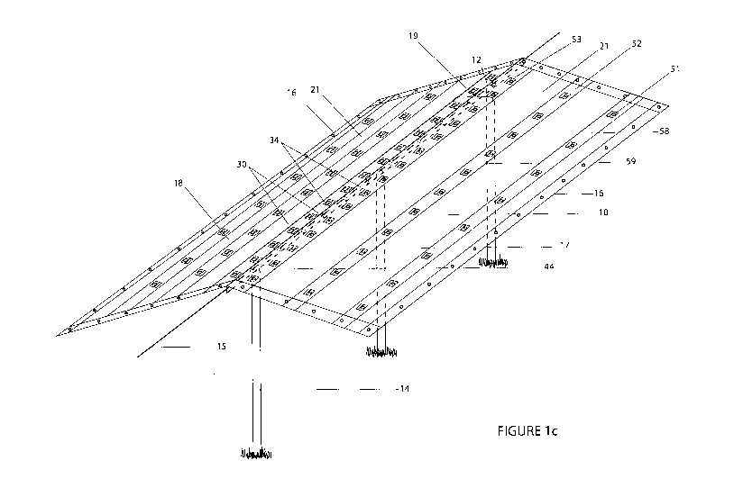
Figure lc is a schematic perspective view of the woven canopy material fixed
over a
central ridge of poles and spanning a ridge cable, and with vent apertures
near the
centre, middle and edge of the material. The canopy material is translucent or
partly
translucent and the supporting structure can be seen through the canopy.
Figure id is a schematic perspective view of the woven canopy material fixed
over a
central ridge of poles and spanning a ridge cable, and with vent apertures
near the
centre of the canopy and near the edge of the material.
Figure 2 is side view of a canopy the same as the canopy of Figure 1c but
without
reinforced areas in some regions of the canopy where vent apertures are
provided.
Figure 3a is an end view of the canopy of Figure la.
Figure 3b is an end view of the canopy of Figure lc with arrows indicating the
flow of air
passing from beneath the canopy to ambient air above the canopy via vent
apertures in
the canopy.
Figure 3c is an end view of the canopy of Figure lc illustrating water running
down an
outside surface of the canopy and vent covers preventing water on the outside
of the
canopy from passing through the vent apertures.
Figure 4a is a schematic cross section view of a section of a canopy to
illustrate one
possible construction.
Figure 4b is a schematic cross section view of a section of a canopy to
illustrate one
possible construction.
Figure 4c is a schematic cross section view of a section of a canopy to
illustrate one
possible construction.
Figure 4d is a schematic cross section view of a section of a canopy to
illustrate one
possible construction.
Figures 5 and 6 show puncture damage to a prior art canopy caused by wear from
a
supporting pole.
Figure 7a is a schematic cross section view of a section of a canopy to
illustrate one
possible construction.
Figure 7b is a schematic cross section view of a section of a canopy to
illustrate one
possible construction with a centre flap and vent apertures on the same side
of the
canopy.
Figure 8a is a part perspective view of the canopy of Figure lb.
Figure 8b is a part perspective view of the canopy of Figure 7b with a centre
flap and
vent apertures on the same side of the canopy.
Figure 8c is a part perspective view of a canopy illustrating another form of
vent cover
over a vent aperture in the canopy.
Figure 8d is a part cross sectional view of the canopy of Figure 8c
illustrating the vent
cover billowing outwards.
CA 02879184 2015-01-14
WO 2014/014365 PCT/NZ2013/000125
- 17 -
Figure Se is a part perspective view of a canopy illustrating another form of
vent cover
over a vent aperture in the canopy.
Figures 8f to 811 are part cross sectional views illustrating vent covers
formed from
sheet material of different weights allowing differing rates of air flow
through vent
apertures.
Figure 9 is a schematic perspective view of a canopy material fixed below a
ridge cable
supported by a support structure, and with vent apertures in the canopy near
the centre,
middle and edge of the material. The canopy material is translucent or partly
translucent
and the supporting structure can be seen through the canopy.
Figure 10a is a part perspective view of a canopy material comprising a vent
region of
netting material adjacent a central region of the canopy.
Figure 10b is a part perspective view of the canopy of Figure 10a with a part
of a cover
covering the vent region lifted to show a portion of the vent region of
netting material
below the cover.
Figure 11 is a part perspective view of a canopy material comprising a vent
region of
netting material adjacent a central region of the canopy with a cover over the
vent region
omitted to show the netting material. An enlarged view of a section of the
venting region
is included.
Figures 12a, 12b, 12c and 12d are cross section schematic views of a section
of a
canopy to illustrate possible constructions comprising a vent region with
cover over the
vent region.
Figure 13a is a part perspective view of a canopy material comprising a vent
region of
netting material adjacent a central region of the canopy with a cover over the
vent region
and an elastic member for biasing the cover towards a closed position over the
vent
region. A portion of the cover is omitted to illustrate the venting region
beneath.
Figure 13b is a cross section schematic view illustrating an elastic member
for biasing
the cover over the vent region towards a closed position over the vent region.
Figures 13c and 13d are cross section schematic views illustrating a member
extending
between the cover over the vent region for limiting the amount the cover may
open away
from the venting region.
Figure 14a is a part perspective view of a canopy material comprising a vent
region of
netting material adjacent a central region of the canopy with a cover over the
vent
region, and a longitudinal fixing flap located a distance from a longitudinal
edge of the
canopy for securing the canopy to a support structure. The portion of the
width of the
canopy outside the fixing flap may hang vertically to extend the covered area
provided
by the canopy.
Figure 14b is a cross section schematic view of a canopy material comprising a
longitudinal fixing flap located a distance from a longitudinal edge of the
canopy for
securing the canopy to a support structure. The fixing flap extends from the
canopy so
CA 02879184 2015-01-14
WO 2014/014365 PCT/NZ2013/000125
- 18 -
that the portion of the width of the canopy outside the fixing flap may hang
vertically
below the main portion of the canopy from inside of the fixing flap.
Figure 14c is a cross section schematic view of a canopy material comprising a
longitudinal fixing flap located a distance from a longitudinal edge of the
canopy for
securing the canopy to a support structure. The fixing flap extends from the
canopy so
that the portion of the width of the canopy outside the fixing flap extends
from above the
main portion of the canopy and from inside of the fixing flap.
Figure 14d illustrates canopies according to the embodiment of Figure 14B
located side-
by-side with curtain portions hanging from below the main portion of the
canopy to
extend the canopies effective area.
Figure 14e illustrates canopies according to the embodiment of Figure 14C
located side-
by-side with cover portions extending from above the main portion of the
canopy and
extending beyond a longitudinal edge of the main portion of the canopy, and
the cover
portions of adjacent canopies overlapping.
DETAILED DESCRIPTION OF EMBODIMENTS
Referring to Figures 1 to 3 lengths of a canopy 10 (see Figure 1) can be fixed
over rows
of for example berry vines or bushes. Figure 4a shows a cross section of the
canopy.
Typically the canopy has a greater length than width, and is provided for use,
as a roll or
in concertina folded form. In use the canopy is supported along a ridge line
12 or peak by
a combination of posts 14 and wires or cables 15 that extend between the
posts. The
case could be the canopy is attached to the wire under the canopy to 44 and
the wire is
supported by posts 14. Longitudinal edges of the canopy may be held in a
stretched out
condition by guys or fasteners connecting between the edge 16 of the canopy
and any
suitable securing point on the ground or on an adjacent frame or wire
extending down
the row length and/or across the row width. In this form the canopy forms a
ridge with
two major surfaces or side 17, 18 as shown in Figure 1 and 3 sloping away from
the
ridge line. The canopy is particularly intended for shedding water to provide
partial
shelter for the plants underneath. The canopy is particularly suited to use
over ripening
berry fruit or other fruits grown on trees. The canopy will typically remain
in place for
some months, before being removed and reused in a subsequent growing season or
on
another crop in the same growing season, but in some cases may remain in place
over
multiple growing seasons.
According to embodiments of the invention, the canopy comprises sheet material
and has
a reinforced centre lengthwise portion 19. The reinforced centre portion 19
has heavier
construction than the material 21 on either side of the reinforced centre
portion. The
reinforced centre portion takes the line and point loading and associated wear
from
CA 02879184 2015-01-14
WO 2014/014365 PCT/NZ2013/000125
- 19 -
contact with the ridge line poles and wires that are underneath the material
in figure la.
This more durable portion has an increased life under the load and wear
conditions than
would be the case for the remainder of the material of the canopy. This
increases the
useful life of the canopy as a whole, without significantly increasing the
overall shading
from the canopy.
The sheet material may be woven from flat warp and weft tapes of a plastics
material
that could be later coated in plastic film on one or both sides; or not
coated.
Alternatively the sheet material could be plastics film. If the sheet material
is woven from
tapes, the tapes may be formed by extruding a film material from a polymer
resin and
then cutting the film into tapes which are in turn used to weave the material,
or by
extruding individual tapes. The tapes may be formed from a polymer containing
pigments
which give the canopy material desired properties, such as desired light
reflective,
absorptive, transmission and/or diffusive properties for example.
If a film the sheet material may be extruded so the reinforced centre
lengthwise portion
of the sheet material is extruded to be thicker than the other, and/or another
layer of
film may be welded, coated or sewn or similar to extruded film sheet to form
the
reinforced centre lengthwise portion.
In embodiments where the sheet material is woven from flat warp and weft
tapes, the
canopy may be woven with heavier warp tapes in the reinforced centre portion
than
outside the reinforced centre portion. For example, in some embodiments the
warp
tapes in the reinforced centre portion have a weight in denier that is at
least 5% greater
than the weight of the warp tapes outside the reinforced centre portion for a
given tape
width. In some embodiments the warp tapes in the reinforced centre portion
have a
weight in denier that is at least 10%, or 20%, or 30%, or 40%, or 50%, or 60%,
or
70%, or 80%, or 90%, or 100% greater than the weight of the warp tapes outside
the
reinforced centre portion for a given tape width. For example, the sheet
material of the
canopy may be woven from warp and weft tapes comprising a nominal tape width
of
about 2mm to 3mm, or 2.4 to 2.6 mm and the warp tapes outside the reinforced
portion
may comprise a nominal weight of about 500 to 1400 denier, 900 to 1400 denier,
or
1000 to 1300 denier, or 1100 to 1200 denier, or 1120 to 1160 denier and the
warp tapes
in the reinforced portion of the canopy may comprise a nominal weight of
greater than
about 1200 denier. In some embodiments, the warp tapes in the reinforced
centre
portion are 100% heavier than the weight of the warp tapes outside the
reinforced centre
portion for a given tape width. That is, the tapes in the reinforced portion
are twice as
heavy as the warp tapes outside the reinforced portion. For example, for a
given tape
width, the warp tapes outside the reinforced portion may comprise a nominal
weight of
CA 02879184 2015-01-14
WO 2014/014365 PCT/NZ2013/000125
- 20 -
about 1100 denier, and the warp tapes in the reinforced portion of the canopy
may
comprise a nominal weight of about 2200 denier. In some embodiments the weight
of
the warp tapes outside the reinforced portion is about 1000 to 1500 denier.
In some embodiments the warp tapes in the reinforced centre portion have a
thickness
that is at least 5% greater than the thickness of the warp tapes outside the
reinforced
centre portion. In some embodiments the warp tapes in the reinforced centre
portion
have a thickness that is at least 10%, or 20%, or 30%, or 40%, or 50%, or 60%,
or
70%, or 80%, or 90%, or 100% greater than the thickness of the warp tapes
outside the
reinforced centre portion. For example, the warp tapes outside the reinforced
portion
may comprise a nominal thickness of about 55 microns, and the warp tapes in
the
reinforced portion of the canopy may comprise a nominal thickness of greater
than about
60 microns. In some embodiments, the warp tapes in the reinforced centre
portion are
100% thicker than the thickness of the warp tapes outside the reinforced
centre. That is,
the tapes in the reinforced portion are twice as thick as the tapes outside
the reinforced
portion. For example, the warp tapes outside the reinforced portion may
comprise a
nominal thickness of about 55 micron, and the warp tapes in the reinforced
portion of the
canopy may comprise a nominal thickness of about 110 micron. In some
embodiments
the thickness of the warp tapes on either side of the reinforced centre
portion is 25
micron to 100 micron.
According to the illustrated embodiments, with particular reference to Figures
4a to 4d
the canopy is constructed from at least one main web 40 of plastics sheet
material (for
example woven sheet material or unwoven sheet material). In some embodiments
the
main web of the canopy is constructed from a single layer of sheet material.
The
reinforced centre portion 19 comprises at least one additional material layer
42 secured
to the main web.
The reinforcing layer may be fixed to the main web by any suitable means, such
as
bonding with adhesives or by heat, or by stitching, or an additional plastic
coating or a
combination of these methods. Preferably the additional material layer is heat
bonded to
the main web along lines or across areas or across substantially its entire
area.
In some embodiments (Figures 4c and 4d) the main web sheet material 40 is
woven from
warp and weft tapes to form a woven sheet material 23, and comprises a coating
layer
24 on one or both sides of the woven sheet material. A coating layer is in
some
embodiments on an outside or top side of the canopy. The coating layer is
preferably a
non-woven sheet material that is melted onto the woven sheet material. For
example,
the coating layer is an extruded sheet melted onto the woven sheet material to
form a
CA 02879184 2015-01-14
WO 2014/014365 PCT/NZ2013/000125
- 21 -
coating over the woven material. In some embodiments the coating layer
material is the
same as the material forming the warp and weft tapes for weaving the main web
of the
canopy. Preferably the coating layer, per side, weighs about 15 to 30 grams
per square
metre. The woven sheet material may comprise a weight of about 65 to 125 grams
per
square meter. In some embodiments the coating is LDPE (low density
polyethylene). In
some embodiments the tapes are HDPE (high density polyethylene). In some
embodiments the coating and/or the warp and weft tapes comprise a UV
stabilizer or
stabilizers.
In some embodiments the additional reinforcing layer 42 has the same
construction as
the sheet material forming the main web of the canopy, comprising a woven
sheet
material with a coating layer. In some embodiments, the additional layer of
sheet
material is applied to the main web of the canopy with the coating layer of
the reinforcing
layer 42 facing downwards, and the coating layer of the main web of the canopy
facing
upwards. In such an embodiment the reinforced central portion of the canopy
comprises
a coating layer on the outside (top side) of the canopy, two layers of woven
material (the
main web 40 and additional layer 42), and a coating layer on the inside
(underside) of
the canopy.
In some embodiments the reinforcing woven layer and the main web material
woven
layer are arranged together with a coating layer on each of the two woven
layers in
contact. For example, where the woven sheet material has a coating on both
sides, the
coating layer on one side of the main web and the coating layer on one side of
the
reinforcing layer contact. Alternatively, where the woven sheet material has a
coating on
one side, the coating layer of the main web and the coating layer on the
reinforcing layer
may contact. Where the coating layers of the main web and the reinforcing
layers
contact, the coating layers may be melted together to join the main web and
the
reinforcing layers together. There may be at least some penetration of the
coating layer
through the woven sheet materials to hold the woven sheet materials together.
The
coating layer typically melts to the woven layers to hold the woven layers
together. In
some embodiments the upper and lower coating layers seals and holds or bonds
the two
layers of woven fabric together. For example, the coating layers are melted to
penetrate
and bond together the two woven layers. In some embodiments, in manufacturing
the
canopy, the woven main web and the woven reinforcing layer 42 are held or
placed
together, and a top coating layer is applied to a top surface of the woven
main web and a
bottom coating layer is applied to an under surface of the reinforcing layer
(and in some
embodiments to the remainder of the underside of the main web), so that the
top and
bottom coating layers join and hold or bond the layers of woven material
together.
CA 02879184 2015-01-14
WO 2014/014365 PCT/NZ2013/000125
- 22 -
In some embodiments a coating layer is added to the main web and to the
reinforcing
layer before the main web and reinforcing layer are joined together. The
coating layer
may be an extruded sheet. The coating layer may cover the full surface of the
main web.
Alternatively, the coating layer may coat a portion of the width of the main
web. For
example, the coating layer may be in a strip or a plurality of spaced apart
strips. For
example, areas 58 and 59 may be coated portions of the main web of the canopy.
In some embodiments, the coat layer or layers may comprise chemical additives
to
impart particular properties to the canopy. For example, the coating material
may
comprise anti drip additives comprising a surfactant.
In some embodiments, the main web of the sheet material is woven from warp and
weft
tapes and the warp tapes in the reinforced centre portion have a greater
weight and/or
thickness than the warp tapes on either side of the reinforced centre portion,
and the
reinforced centre portion may in addition also comprises at least one
additional material
layer 42 secured to the centre portion of the main web which may also
comprising the
heavier warp tapes.
In the illustrated embodiments the canopy includes securing features 44 within
the
region of the reinforced centre portion 19. In particular the canopy includes
a flap 46
extending from the reinforced centre portion. At least one securing feature 48
is located
in or on the flap. The flap extends for substantially the whole, or at least a
majority, of
the length of the canopy. In some embodiments a series of independent flaps
may be
provided dispersed along the length of the canopy.
In the illustrated embodiment the flap 46 in Figures 4a and 7a is developed by
an
extension of the web 40. The web 40 may be constructed from two parts, with
edge
portions of the two parts secured together by heat sealing, adhesive bonding
or sewing.
The secured edge portions form the flap 46. As described above, in some
embodiments
the web sheet material 40 may comprise a coating on one or both sides. In such
embodiments, the coating layer(s) is also formed into the flap together with
the woven
sheet material. For example, the flap may comprise a coating layer on a first
side of the
flap, two layers of woven material separated from another two layers of woven
material
by two coating layers, and another coating layer on an opposite second side of
the flap.
One or more extra material layers may be included in the flap. For example a
covering
layer 43 in Figures 4a, 4b and 7a, 7b of material may be folded over the
outside of the
flap and be heat bonded, adhesively bonded or sewn to the flap.
CA 02879184 2015-01-14
WO 2014/014365 PCT/NZ2013/000125
- 23 -
In the illustrated embodiment, at least one securing feature is an aperture 47
(Figures 4a
and 7a) in the flap. The aperture may be provided with reinforcing such as a
plastic or
metal eyelet or grommet such as 48 in Figure 4a and 7a.
Alternatively the securing feature might be a hook or clip or tag line bonded
or sewn to a
flap, or bonded or sewn directly to the reinforced centre portion of the
canopy.
In the illustrated embodiment the flap comprises at least one layer of the
main web of
canopy material. The flap illustrated comprises two layers of the main web of
canopy
material bonded together. The flap may be folded from the web sheet material
to form
two layers joined at a fold. In the illustrated embodiment the two layers each
end at an
edge at the edge of the flap, the main we formed from two parts as described
above.
The additional material layer of the reinforced centre portion of the canopy
may be
provided into the flap as well as adjacent the flap, as illustrated in Figure
4a.
Alternatively, the additional material layer of the reinforced centre portion
of the canopy
is provided only adjacent to the flap, so that a separate web of reinforcing
material is
provided at either side of the flap 46.
The flap may be provided with one or more additional reinforcing layers. For
example an
edging tape or strip or belt of material 43 may be folded over the outside of
the flap as
illustrated in Figure 4a. The edging tape or strip or belt of material may be
secured in
any suitable fashion such as stitching, adhesive or heat bonding. The edging
tape may be
sufficiently wide to substantially cover both faces of the flap.
In other embodiments the flap may comprise a fold of the reinforcing sheet
material,
such that the reinforcing sheet material forms a double layer as the flap, and
extends
away from the flap on either side where the flap joins to the main web of the
canopy.
The double layer of the flap may be heat bonded together or sewn along one or
more
lines to secure the two layers together.
In some embodiments the longitudinal centre portion of the canopy is not
reinforced, as
illustrated in Figures 4b and 7b. As illustrated in Figures 4b and 7b, the
flap 46 may
comprise two layers of the sheet material that forms the main web of the
canopy.
However, in some embodiments, the flap 46 may include additional layers of
reinforcing
material. For example, the flap in Figures 4a and 7a may comprise the same
construction as the flap in Figure 4a, however, the additional reinforcing
layer 42 is
applied in the flap 46 only and does not extend into the central portion of
the canopy so
that the central portion is not reinforced by the reinforcing layer 42.
CA 02879184 2015-01-14
WO 2014/014365 PCT/NZ2013/000125
- 24 -
The flap may comprise additional layers of material, for example one or more
reinforcing
members may be located and secured within or over the folded double layer, or
the
single sheet of reinforcing material may include multiple folds to form a flap
with multiple
stacked layers.
In use, the securing features located within the area of the reinforced
portion of the
canopy are connected to the supporting ridge wire or to the supporting poles.
This
ensures that the reinforcing centre portion of the canopy stays in position
over the ridge
wire and/or supporting poles.
In at least some embodiments, the canopy, or at least the parts of the canopy
that are
outside the reinforced portion, or just the reinforced portion, are
transparent or
translucent to transmit light to plants beneath the canopy in use. By
transparent or
translucent we mean that the material may transmit at least 50% of solar
radiation on
average across the UV (wavelength about 280-400 nm), visible (wavelength about
400-
700 nm) and very near infrared (wavelength about 700-800 nm) ranges, and which
transmits at least 10% on average of solar radiation across the wavelength
range about
800-2500nnn.
The canopy may also include UV absorbers to reduce the amount of UV that is
part of the
transmitted light below the canopy for the benefit of the plants below the
canopy.
In some embodiments the sheet material of the canopy is white in colour. The
sheet
material may alternatively be another colour such as red or green or blue or
silver, or be
clear.
In some embodiments the reinforced centre portion 19 of the canopy has a width
of
between 3 to 50 cm, or 5 to 30 cm or 5 to 20 cm, and the overall width of the
canopy is
between 1-12 metres, or 1.5 to 6 metres, or 2 to 5 metres or 2.5 to 3.5
metres, or 2.8 to
3.2 metres for example.
Edges of the canopy may include fastening features. For example the canopy may
include a reinforced edge 55 and a plurality of spaced apart fastening
locations, such as
rings, hooks or eyes (as at 57) or apertures located in the reinforced edge.
Reinforced
edges may be provided by bonding a folded edge tape over the edge of the main
web of
the canopy.
CA 02879184 2015-01-14
WO 2014/014365 PCT/NZ2013/000125
- 25 -
The material of the main web of the canopy may have a tight weave or high
weave
density so that the canopy has low or negligible water permeability.
Additionally or
alternatively the web may be coated with a continuous coating of a plastics
material for
example by extrusion coating at manufacture of the material. Alternatively
again the
material may be heat treated to melt or partially melt bond the warp and weft
tapes
together to be water impermeable.
Preferably securing of additional layers of material, such as for reinforcing
the centre
portion, or for reinforcing the edges of the material, is by methods that are
non-piercing
of the material, such as heat bonding, or by pressed together the two layers
then coating
on the outside of the two layers, on the up (top) side and on the down side,
two layers of
coating, to seal and hold the two layers of woven fabric together. So
preferably the
securing is not by stitching.
In some embodiments the material may incorporate a compound or compounds added
to
eliminate or reduce the extent to which the material forms water droplets of,
for
example, condensation. The anti drip additives may comprise, for example, a
non-ionic
surfactant. The anti drip additive may be included in coatings applied to a
woven
substrate, or in polymer tapes of the woven substrate.
As stated the tapes may be formed from a polymer containing pigments which
give the
canopy material desired properties, such as desired light transmission
properties for
example. Some or all tapes of a reflective material may be formed from a resin
comprising a white pigment, which resin has been formed by mixing a
nnasterbatch
consisting essentially of 1 to 90% by weight of a white pigment or combination
of
pigments chosen from zirconium, strontium, barium, magnesium, titanium, zinc
and
calcium pigments, and a first polymer, with a second polymer such that the
resin
(masterbatch) comprising the white pigment comprises between about 1 to 50% by
weight of the total mixture. In certain embodiments the white pigment may be
selected
from zirconium dioxide, magnesium zirconate, calcium zirconate, strontium
zirconate,
barium zirconate, zirconium silicate, zinc sulphide, calcium carbonate, barium
sulphate,
magnesium oxide, strontium carbonate, barium carbonate, titanium dioxide, zinc
oxide
and potassium titanate.
In some embodiments the canopy 10 comprises vent apertures 30 in the
reinforced
centre region 19 of the canopy 10, illustrated in Figures lb, lc, ld, 7a, 7b
and 8a. The
vent apertures 30 may allow hot or warm air beneath the canopy to escape from
beneath
the canopy to ambient air above the canopy. The vent apertures 30 may also
allow
higher air pressure beneath the canopy, caused by such things as wind to
escape to
CA 02879184 2015-01-14
WO 2014/014365 PCT/NZ2013/000125
- 26 -
lower air pressure above the canopy. In some embodiments the vent aperture may
include a reinforcing grommet or eyelet 32. In some embodiments, a vent cover
34 is
provided over each vent aperture. The vent cover or flap 34 restricts water
from flowing
or entering the vent aperture and passing from outside the canopy to inside
the canopy
but allows air to move upwards though the vent.
In the illustrated embodiment, a separate vent cover 34 is provided at each
vent
aperture 30. In other embodiments, a continuous cover or flap extending
longitudinally
along the canopy may cover more than one vent aperture 30. In some embodiments
the
vent cover has a width of about 4cm to 14cm. In some embodiments the vent
apertures
have a diameter of less than about 100mm. In some embodiments the vent
apertures
have a diameter of about 60mm, 50mnn, 40mnn, 35mm, 30mm, 25mm, or 20mm, or
15mm, 12mm, or 10mm.
In some embodiments the vent apertures are provided to the reinforced centre
portion
19 of the canopy. In some embodiments the vent apertures are provided near to
or
adjacent to the centre or ridge line 12 of the canopy. In some embodiments the
vent
apertures are positioned at about a midpoint between an edge 22 of the
reinforced
centre portion 19 and the flap 46 comprising securing features 44. For
example, in an
embodiment where the reinforced portion is 30cm wide, the vent aperture is
located at
about 8cm from the centre of the reinforced portion 19, or 8cm from the flap
46
comprising the securing features 44. In some embodiments, the vent apertures
are
closer to the centre of the canopy than the edge 22 of the reinforced portion
19 of the
canopy. For example, in an embodiment where the reinforced portion is 30cm
wide, the
vent aperture is located at about 3cm to 4cm from the centre of the reinforced
portion
19, or 3cm to 4cm from the flap 46 comprising the securing features 44. In
some
embodiments the vent apertures are located about 5cm to 20cm, or from 7cm to
13cm,
or 8cm to 12cnn, or 9cm to 11cm, or about 10cm from the centre 12 of the
canopy. In
some embodiments, the vent apertures are placed at or adjacent to the edge 22
of the
reinforced centre portion 19. In some embodiments, the vent apertures may be
placed
adjacent to the ridge line or flap 46 of the canopy.
The vent cover 34 may be attached to the reinforced portion of the canopy at
or adjacent
to a longitudinal edge 35 of the vent cover that is positioned above the vent
aperture in
use. The vent cover 34 may be attached to the reinforced portion of the canopy
at or
adjacent to a longitudinal edge 35 of the vent cover that is located between
the ridge line
12 of the canopy and the vent aperture 30. The vent cover may be fixed to the
reinforced portion by any suitable means, such as bonding with adhesives or by
heat, or
CA 02879184 2015-01-14
WO 2014/014365 PCT/NZ2013/000125
- 27 -
by stitching (33 in Figures 8 and 8b), or a combination of these methods. In
use, water
is restricted from entering the vent aperture by the cover 34.
In some embodiments, a lateral side or sides 36 of the vent cover may be
attached to
the canopy reinforced portion 19, in part or in full, to reduce any side way
entry of water
under the vent cover.
The vent cover may be formed from a piece or strip of material. The vent cover
material
may be woven from flat warp and weft tapes of a plastics material or woven
from flat
warp and weft tapes of a plastics material that has later been coated on one
or both
sides. Alternatively the cover material could be plastics film. In some
embodiments the
vent cover is formed from the same sheet material as the canopy sides. In the
illustrated embodiment of Figures 8a and 8b, the vent cover 34 is formed from
a folded
piece of sheet material. The sheet material of the vent cover is folded about
a fold line
31. An outer side 37 of the sheet material of the vent cover forms the vent
cover 34. An
inner side 38 of the sheet material is attached to the reinforced portion of
the canopy.
For example, in some embodiments, the vent aperture may include a reinforcing
grommet or eyelet 32, and the inner side 38 of the vent cover sheet material
is attached
to the canopy by the grommet or eyelet extending through the inner side 38 and
the
canopy. In some embodiments, the inner side of the vent cover material may be
attached to the canopy around a perimeter of the vent aperture by bonding with
adhesives or by heat, or by stitching, or a combination of these methods. In
some
embodiments the vent cover is formed from a material that is formed in a
cylinder. The
cylinder is flattened or folded to form the inner side 38 and the outer side
37, the vent
aperture 30 being formed through the inner side, and the outer side of the
cylinder of
material forming the vent cover 34 over the vent aperture.
In some embodiments the outer side or vent cover 34 is attached to the inner
side of the
strip or cylinder of material along a longitudinal edge 35 of the vent cover
above the vent
aperture relative to a ridge line of the canopy. For example, the outer side
may be
bonded with adhesive or by heat, or by stitched to the inner side. In some
embodiments
at least an upper portion of a lateral side or sides 36 of the vent cover may
be attached
to the inner side of the strip or cylinder of material to help restrict the
amount the vent
cover lifts away from the venting aperture. In some embodiments the inner side
of the
strip or cylinder of material is only attached to the canopy main web or sheet
material
around the aperture 30, for example by a grommet 32 around the vent aperture.
The inner side of the material of the vent cover provides reinforcement to the
vent
aperture. For example, in some embodiments, the canopy comprises three layers
of
CA 02879184 2015-01-14
WO 2014/014365 PCT/NZ2013/000125
- 28 -
material at the vent aperture; the main web of the canopy 40, an additional
material
layer 42 for reinforcing the centre region 19 of the canopy, and the inner
side 38 of the
vent cover sheet material. In some embodiments the vent cover is provided
without an
inner side 38 so that the vent aperture is formed through the reinforced
portion of the
canopy and without further reinforcement provided by the additional layer of
an inner
side 38 of the vent cover sheet material.
In Figure 8 the vent cover 34 is illustrated in a folded out position. In some
embodiments, in use the vent cover 34 may lie flat against the vent aperture
30.
In the embodiment illustrated in Figure lb, the vent apertures 30 are located
adjacent to
a securing feature 44 along the length of the canopy. In the illustrated
embodiment, the
vent apertures are located at alternate sides of the ridge 12 along the length
of the
canopy. In the embodiment of Figure lb, the vent apertures on each side of the
ridge 12
are aligned. In some embodiments, as shown in Figure id, the vent apertures on
one
side (first side) of the ridge 12 are staggered with the vent apertures on the
other side
(second side) of the ridge.
In some embodiments the canopy comprises vent apertures 30 without a
reinforced area
in the centre part of the canopy. For example, in the embodiments illustrated
in Figures
4b, 7b and 8b, the canopy is provided with a flap 46 comprising securing
features 44.
The flap 46 extends above the canopy to secure the canopy from above the
canopy, for
example by a wire extending through the securing features 44. In the
embodiments of
Figures 4b, 7b and 8b, the canopy is hung from the securing features 44 and
the centre
portion of the canopy may not rest on ridge line poles. Such a canopy may not
comprise
a reinforced central portion. An example canopy comprising an outwardly
extending flap
with securing features and a support structure for supporting such a canopy is
provided
in Figure 9.
In an embodiment without a reinforced portion, the vent apertures 30 may be
located in
a longitudinally extending centre region of the canopy to be near to or
adjacent the
centre of the canopy. For example the vent apertures may be at about 7cm to
13cm, or
8cm to 12cm or 9cm to 11cm or about 10cm from the centre 12 of the canopy. The
vent
apertures may comprise a vent cover as described above. For example, the
canopy may
comprise two layers of material at the vent aperture; the main web 40 of the
canopy and
the inner side 38 of the vent cover material. In some embodiments the vent
cover is
provided without an inner side 38 so that the vent aperture is formed through
the main
web 40 of the canopy and without further reinforcement provided by the
additional layer
of an inner side 38 of the vent cover material.
CA 02879184 2015-01-14
WO 2014/014365 PCT/NZ2013/000125
- 29 -
In some embodiments, vent apertures are provided outside a centre portion 19
of the
canopy, for example as illustrated in Figures 1c and 2. For example, the
canopy may
comprise vent apertures 30 located in a longitudinal extending edge region of
the canopy
to be positioned towards or near to a longitudinal edge of the canopy 10. For
example, a
longitudinal row or group 51 of vent apertures may be positioned 5cm to 50cm,
or 5cm
to 30cm, or 5cm to 20cm, or about 10cm from a longitudinal edge of the canopy
(referred to herein as an edge region of the canopy). However, the apertures
in the
edge region may not be aligned in a row.
In some embodiments the canopy may comprise vent apertures 52 located in a
longitudinally extending intermediate region of the canopy between a centre 12
or centre
region or ridge of the canopy and a longitudinal edge or edge region of the
canopy. For
example, the canopy may comprise a longitudinal row or group of vent apertures
52
located approximately midway between a centre 12 of the canopy and a
longitudinal
edge of the canopy. For example, for canopies that are 1m to 10m wide, the
midpoint
for the longitudinal extending intermediate region would be 0.25m to 2.5m from
the
longitudinal edge of the canopy. In some embodiments the longitudinally
extending
intermediate region of the canopy is between 5cm from a longitudinal edge of
the canopy
and 10cm from a centre 12 of the canopy. In some embodiments the
longitudinally
extending intermediate region of the canopy is between 10cm from a
longitudinal edge of
the canopy and 15cm from a centre 12 of the canopy. In some embodiments the
canopy
comprises vent apertures 50cm to 200cm, or 50cm to 150 cm, or 50 cm to 100cm
from a
longitudinal edge of the canopy. The apertures may not be aligned in a row.
In some embodiments, the canopy comprises more than one longitudinal row or
group of
vent apertures. For example, a canopy may comprise more than one of a
longitudinal
row or group 51 of vent apertures located towards or near to a longitudinal
edge of the
canopy 10 (referred to herein as an edge region of the canopy), a longitudinal
row or
group of vent apertures 52 located approximately midway between a centre 12 of
the
canopy and a longitudinal edge of the canopy, and a longitudinal row or group
of vent
apertures 53 located near to or towards a centre 12 of the canopy. The vents
could also
be placed randomly in each side of the canopy so they are not in a distinct
pattern or in
rows.
As described above, in some embodiments the canopy comprises vent apertures in
the
centre portion 19 (that is reinforced or not reinforced) of the canopy, and
also vent
apertures outside the centre portion, for example rows of vent apertures 51
and 52. In
some embodiments, the canopy sheet material is reinforced in the regions where
vent
CA 02879184 2015-01-14
WO 2014/014365 PCT/NZ2013/000125
- 30 -
apertures are located. For example, in some embodiments the canopy comprises
vent
apertures 51 located in a longitudinal extending reinforced edge region of the
canopy to
be positioned towards or near to a longitudinal edge of the canopy 10. For
example, a
longitudinal row or group 51 of vent apertures may be positioned in a
longitudinally
extending reinforced portion of the canopy located 5cm to 50cm, or 5cm to
30cm, or 5cm
to 20cm, or about 10cm from a longitudinal edge of the canopy. In some
embodiments,
the canopy comprises vent apertures 52 in a longitudinal extending reinforced
region of
the canopy positioned intermediate of the centre portion of the canopy and an
edge
region of the canopy. For example, a longitudinal row or group 52 of vent
apertures may
be positioned in a longitudinally extending reinforced portion of the canopy
located
between 10cm from a longitudinal edge of the canopy and 15cm from a centre 12
of the
canopy, or 50cm to 200cm from a longitudinal edge of the canopy, or 50cm to
150 cm,
or 50 cm to 100cm from a longitudinal edge of the canopy. The longitudinal
reinforced
portions of the canopy may comprise the construction as described for the
centre
reinforced portion of the canopy. For example the reinforced portions of the
canopy,
whether in a central region 19, an edge region 58, or a region 59 that is
intermediate the
edge and central regions may comprise heavier warp tapes and/or an additional
layer or
layers of sheet material and/or an additional plastic coating.
In one embodiment, the vent apertures 53 located near to a ridge of the canopy
may be
spaced apart along the longitudinal direction of the canopy at a distance of
20cm to
200cm, 20 cm to 1,50cm, 20cm to 100cm, or 30cm to 90cm, or 40cm to 80cm, or
50cm
to 70cm, or about 60cm. In one embodiment, the vent apertures 52 located
intermediate the ridge and longitudinal edge of the canopy may be spaced apart
along
the longitudinal direction of the canopy at a distance of 50cm to 200cm, 50cm
to
130cm, or 60cm to 120cm, or 70cm to 110cm, or 80cm to 100cm, or about 90cm. In
one embodiment, the vent apertures 51 located near to or adjacent a
longitudinal edge
of the canopy may be spaced apart along the longitudinal direction of the
canopy at a
distance of 20cm to 200cm, 80cm to 160cm, or 90cm to 150cm, or 100cm to 140cm,
or
110cm to 130cm, or about 120cm. So in some embodiments, the vent apertures in
the
longitudinal centre portion or region may be spaced closer together along the
length of
the canopy compared to the vent apertures in the edge region and/or in the
intermediate
region. Alternatively, in some embodiments, the vent apertures in the edge
region may
be spaced closer together than the vent apertures in the centre portion. In
some
embodiments, the spacing between vent apertures in the edge may be the same as
the
spacing between the vent apertures in the centre region. In some embodiments
the vent
apertures in the intermediate region are spaced closer together than the vent
apertures
in the central region. In some embodiments, the spacing between vent apertures
in the
intermediate region may be the same as the spacing between the vent apertures
in the
CA 02879184 2015-01-14
WO 2014/014365 PCT/NZ2013/000125
- 31 -
centre region. In some embodiments, the vent apertures in the edge region are
spaced
closer together than the vent apertures in the intermediate region. In some
embodiments, the spacing between vent apertures in the intermediate region may
be the
same as the spacing between the vent apertures in the edge region.
The vents can also be placed in other locations in the canopy. For example,
vent
apertures may be positioned as illustrated in figures lb, lc and id, and/or
vent
apertures may be placed randomly throughout the canopy. Vent apertures located
towards or near to a longitudinal edge of the canopy may be particularly
useful for
preventing water pooling on top of the canopy in a region extending along a
longitudinal
edge of the canopy. For example, in use, water running down the canopy may
collect in
a region near to the longitudinal edge of the canopy where the canopy is
installed without
sufficient tension to allow water to run off the canopy. The weight of the
water can
cause the canopy to form a concave shape near the longitudinal edge where
water
collects and builds up on the canopy. Vent apertures with covers near to the
longitudinal
edge may act as relief valves to allow water pooling or collecting in this
region of the
canopy to leak or drain from the canopy to avoid water remaining on or being
captured
by the canopy or the water is limited to an area beneath the location of the
vent
apertures in the edge region of the canopy (the amount of water cannot build
up towards
the centre of the canopy beyond the location of the vent apertures). This
reduces the
downward water pressure on the canopy caused by pooling water. In some
embodiments the vent apertures in the edge region of the canopy are not
covered by
vent covers, as illustrated in Figure id, to allow water at the edge region of
the canopy
to drain through the canopy via the vent apertures in the edge region. In some
embodiments, the vent apertures in the edge region are spaced closer together
than the
vent apertures in the central region, to provide sufficient vent apertures in
the edge
region to allow water to leak through the canopy at the edge region to prevent
the
pooling of water at the edge region of the canopy. For example, in some
embodiments,
the vent apertures at the edge region are spaced apart by 20 cm to 200 cm, 20
cm to
150cm, 20cm to 100cm, or 30cm to 90cm, or 40cm to 80cm, or 50cm to 70cm, or
about
60cm, whereas the vent apertures in the central region are spaced apart by
80cnn to
160cm, or 90cm to 150cm, or 100cm to 140cm, or 110cm to 130cm, or about
120cnn.
The vent apertures may also allow air pressure due to wind or breeze to be
released from
beneath the canopy. Vent apertures may allow wind or breeze to pass through
the
canopy from below the canopy to ambient above the canopy. In a breezy or windy
climate, wind passing below the canopy may cause the canopy to billow
outwards,
straining any securing features or support structures retaining the canopy in
place. The
vent apertures may allow wind or breeze to pass through the canopy and reduce
CA 02879184 2015-01-14
WO 2014/014365 PCT/NZ2013/000125
- 32 -
billowing of the canopy in a windy climate. The vent apertures may allow
cheaper or
lighter weight securing devices to be used to secure the canopy.
In use, hot air accumulating under the canopy rises towards the ridge of the
canopy.
Vent apertures near to the top of the canopy near the ridge 12 allow hot air
to exit the
canopy to ambient air above the canopy. The vent covers restrict water above
the
canopy from entering the vent apertures to assist in maintaining a dry
environment
under the canopy in at least a central area under the canopy.
In some embodiments vent apertures in the longitudinally extending centre
portion of the
canopy have a larger diameter than the vent apertures in other regions of the
canopy.
For example the vent apertures 53 in the centre portion are larger than the
vent
apertures 51 in a longitudinal edge region of the canopy, and/or the vent
apertures 52 in
an intermediate region between the longitudinal edge region and the centre
portion of
the canopy. The larger diameter apertures provide for increased breeze or
airflow to
pass from beneath the canopy to exit the canopy to ambient air above the
canopy. For
example, the diameter of the vent apertures in the central portion of the
canopy may
comprise a diameter of 10mm to 100mm, 20mm to 50mm, or 25mm to 45mm, or 30mm
to 40mnn. The vent apertures in other regions of the canopy may comprise a
diameter of
5mm to 25mm, or 10mm to 20mm, or 20mm to 40 mm.
The larger sized vent covers required to cover the larger diameter vent
apertures may be
more prone to being blown open compared to vent covers over smaller diameter
vent
apertures. Preferably a vent cover lifts away from or is positioned from the
vent aperture
enough to allow sufficient air flow while preventing or significantly
restricting water flow
from outside the canopy.
As described above, in some embodiments, the vent cover may be formed from a
folded
piece or strip of material or a strip material formed into a cylinder and
folded. An outer
side of the strip or folded cylinder of material forms the vent cover, and an
inner side of
the strip or folded cylinder of material is attached to the canopy. For
example the inner
side is attached to the canopy by a grommet forming the vent aperture through
the inner
side and the sheet material of the canopy.
To restrict the amount the vent cover lifts away from the vent aperture, in
some
embodiments the vent cover is attached to the inner side of the strip or
cylinder of
material along a longitudinal edge 39 of the vent cover below the vent
aperture, as
illustrated in Figure 8C. In some embodiments the outer side 37 is releasably
attached
to the inner side 38 along a longitudinal edge 39 of the vent cover below the
vent
CA 02879184 2015-01-14
WO 2014/014365 PCT/NZ2013/000125
- 33 -
aperture 30. For example, a hook and loop type fastener may be applied along
the
longitudinal edge of the vent cover and the inner side of the strip or
cylinder of material
below the vent aperture.
Further, in some embodiments, at least an upper portion of a lateral edge or
edges 36 of
the outer side are attached to the inner side. For example, the vent cover 34
is fixed to
the inner side 38 from the top of the vent cover to approximately half way
down each
lateral edge 36 of the vent cover.
Where the inner side 38 of the strip or cylinder of material is not attached
to the canopy
main web or sheet material except around the perimeter of the vent aperture
(for
example by a grommet 32), and the vent cover 34 is attached to the inner side
along
longitudinal edges 35, 39 above and below the vent aperture 30, a breeze or
air
movement may cause the vent cover 34 and the inner side 38 of the vent cover
material
to billow outwards from the aperture, as illustrated in the cross sectional
view of Figure
8D. However, as the vent cover is attached to the inner side 38 along
longitudinal edges
35, 39 above and below the vent aperture, the vent aperture always remains
covered,
even when a strong breeze blows through the vent aperture.
In some embodiments the lateral dimension of the vent cover between the
longitudinal
edges 35, 39 of the vent cover is greater than the lateral dimension of the
inner side
between the longitudinal edges 35, 39 so that the vent cover 34 arches or bows
outwardly from the vent aperture, as illustrated in Figure 8e. This embodiment
helps to
ensure the vent cover is spaced a distance from the vent aperture, even when
there is no
substantial breeze or air flow passing through the vent aperture to cause the
vent cover
to billow outwards. With the vent cover held or bowed outwards from the vent
aperture,
a low resistance path for venting air from below the canopy is provided, while
the vent
aperture remains covered.
In some embodiments, the vent cover may be formed from a sheet material
comprising a
particular weight suitable for an intended amount of air flow. The weight of
the material
of the vent covers may regulate the amount of air flow through the vent
apertures. For
example, a vent cover formed from a light weight sheet material may allow a
higher flow
of air through a vent aperture compared to a vent cover formed from a heavier
weight
sheet material. And a vent cover formed from a relatively intermediate weight
material
may allow a relatively intermediate flow rate of air through a vent aperture
compared to
lighter and heavier vent cover materials. This concept is illustrated in
Figures 8f to 8h.
In Figure 8f, the vent cover 34a is formed from a light weight sheet material
and lifts
relatively easily away from the vent aperture to allow a larger air flow rate
through the
CA 02879184 2015-01-14
WO 2014/014365 PCT/NZ2013/000125
- 34 -
aperture. In Figure 8g, the vent cover 34b is formed from a relatively
intermediate
weight sheet material and lifts less easily away from the vent aperture
compared to vent
cover 34a. In Figure 8g, the vent cover 34c is formed from a relatively heavy
weight
sheet material and lifts less easily away from the vent aperture compared to
vent covers
34a and 34b and allows a relatively smaller air flow rate through the vent
aperture.
The vent cover that is also heavier will also take more wind force to be
lifted than a
lighter weight vent cover. Thus the weight of the vent cover may be chosen to
regulate
the amount of wind force required to lift a vent cover. Higher wind force will
be required
to lift the vent cover comprising a heavier weight material and thus a heavier
weight vent
cover will stay closer to the vent aperture in higher wind conditions and
restrict rain
associated with the wind from penetration though the vent aperture to the crop
below.
The vent cover is still not so heavy that it will not lift to allow a flow of
air from beneath
the canopy to reduce high wind pressure on the canopy.
In some embodiments the vent covers are formed from a relatively light weight
sheet
material comprising a weight of about 50 to 200g/m2. In some embodiments the
vent
covers are formed from a relatively intermediate weight sheet material
comprising a
weight of about 200 to 400g/m2. In some embodiments the vent covers are formed
from
a relatively heavy weight sheet material comprising a weight of about 400 to
10009/m2.
In some embodiments the vent covers are formed from a relatively light weight
sheet
material comprising a weight of about 50 to 100g/m2. In some embodiments the
vent
covers are formed from a relatively intermediate weight sheet material
comprising a
weight of about 100 to 200g/m2. In some embodiments the vent covers are formed
from
a relatively heavy weight sheet material comprising a weight of about 200 to
600g/m2.
In some embodiments, the canopy may comprise some vent covers that comprise a
relatively light weight sheet material, and some vent covers that comprise a
relatively
heavy weight sheet material. For example, the vent apertures in the
longitudinally
extending centre portion of the canopy may be covered with vent covers
comprising a
lighter weight material, and the vent apertures in other regions of the canopy
may be
covered with vent covers comprising a heavier weight material. The lighter
weight
material allows a higher air flow through the vent apertures in the centre of
the canopy
compared to flow through apertures covered with a heavier material in other
regions of
the canopy.
In some embodiments, the position of the vent aperture in the canopy
determines the
weight of the vent cover material. Vent covers over vent apertures positioned
directly
CA 02879184 2015-01-14
WO 2014/014365 PCT/NZ2013/000125
- 35 -
over a crop should have more resistance to lifting in windy conditions
compared to covers
over vent apertures that are not positioned directly over the crop. Therefore,
for
example, the vent covers over apertures in a central region of the canopy may
comprise
heavier weight material, and vent apertures in an edge region of the canopy
may
comprise lighter weight material, where the canopy is intended to be
positioned centrally
over a row of trees.
For example, the vent apertures in the central portion of the canopy may
comprise vent
covers comprising a material weight of 200 to 1000g/m2, and the vent apertures
in an
edge region of the canopy may comprise vent covers over comprising a material
weight
of 50 to 200g/m2.
In some embodiments vent apertures in one region of the canopy may have a
larger
diameter than the vent apertures in other regions of the canopy. For a larger
diameter
vent aperture, the vent cover is correspondingly larger compared to the vent
covers over
smaller vent apertures in the canopy. To assist with maintaining a cover over
the larger
apertures, in some embodiments the vent covers over the larger diameter
apertures
comprise a heavier weight material, and smaller diameter vent apertures in
other regions
of the canopy material are covered with vent covers comprising lighter weight
material.
Further, due to the larger surface area of the vent covers over larger vent
apertures, the
covers over larger vent apertures may be more prone to being lifted by wind
passing
over the canopy. To reduce the likelihood or occurrence of larger vent covers
lifting
away from larger vent apertures in windy conditions, in some embodiments the
vent
covers over larger vent apertures are formed from heavier weight material, and
the vent
covers over smaller vent apertures are formed from lighter weight material.
For a
canopy, the material weight of vent covers over larger vent apertures in the
canopy may
be heavier than the material of vent covers over smaller vent apertures in the
canopy so
that the vent covers over the larger apertures and the vent covers over the
smaller
apertures require a similar amount of wind force to lift away from the larger
and small
vent apertures. This provides even or uniform protection for plants below the
canopy
regardless of where the plants are positioned beneath the canopy.
For example, the diameter of the vent apertures in a first region (for example
a central
portion) of the canopy may comprise a diameter of lOmm to 100mm, 20mm to 50mm,
or 25mm to 45mm, or 30mm to 40mm or 40mm to 50mm, and the vent covers over the
vent apertures in the first region of the canopy may comprise a material
weight of 200 to
1000g/m2. In comparison, the vent apertures in second region (for example an
edge
region) of the canopy may comprise a diameter of 5mm to 25mm, or 10mm to 20mm,
CA 02879184 2015-01-14
WO 2014/014365
PCT/NZ2013/000125
- 36 -
and the vent covers over the vent apertures in the second region of the canopy
may
comprise a material weight of 50 to 200g/m2.
Conversely, larger diameter vent covers may comprise lighter weight material
vent
covers compared to other smaller diameter vent covers, so that an even greater
increased flow of air is achieved through the larger vent apertures.
In some embodiments the canopy comprises vent covers formed from a heavier
weight
sheet material than the sheet material of the main portion of the canopy. In
some
embodiments the canopy comprises vent covers formed from a lighter weight
sheet
material than the sheet material of the main portion of the canopy. In some
embodiments, some vent aperture covers are formed from a heavier weight sheet
material, and some vent covers formed from a lighter weight sheet material,
and the
main portion of the canopy is formed from an intermediate weight sheet
material.
In some embodiments the vent covers are formed from the same weight sheet
material
as the sheet material of the main portion of the canopy.
In very windy environments the vent apertures may not provide sufficient
venting
surface area to allow sufficient air flow from below the canopy.
In some embodiments, the canopy may comprise a venting region at or adjacent
to the
central region of the canopy. In windy environments, wind flow below the
canopy may
rise up the canopy to exit the canopy via the vent region to prevent the
canopy billowing
outwards. The venting region thus reduces force on the canopy, fasteners
fastening the
canopy to supporting structures, and supporting structures holding the canopy
in place.
Figures 10a and 10b illustrate embodiments of a canopy comprising a venting
region 60.
In some embodiments a vent region cover 70 may cover the venting region 60.
The
cover 70 restricts water from flowing or entering the vent region and passing
from
outside the canopy to inside the canopy and onto the plants but allows air to
move
upwards though the vent region.
In some embodiments the venting region may comprise netting material. In some
embodiments, the venting region extends longitudinally along the length of the
canopy,
for example in a region of the canopy bridging the apex or ridge line of the
canopy in
use. In some embodiments, the venting region may be formed in sections spaced
apart
along the length of the canopy. In some embodiments, the cover 70 extends
longitudinally along the length of the canopy to cover the venting region. In
the
CA 02879184 2015-01-14
WO 2014/014365 PCT/NZ2013/000125
- 37 -
embodiment of Figure 10a, the lateral ends of the cover 70 are not affixed to
the lateral
ends of the canopy. In the embodiment of Figure 10b, the lateral ends of the
cover 70
are affixed to the lateral ends of the canopy to prevent weather (rain)
passing from
outside or above the canopy to inside or below the canopy at the lateral ends
of the
canopy. In Figure 10b, the cover is illustrated as being lifted away from the
venting
region 60 so that the venting region below the cover 70 may be viewed in the
Figure.
In some embodiments the venting region extends along one or both sides of the
ridge 12
of the canopy. The venting region may extend up to 100mm, or 200mnn or 300mm
or
400mm or 500 mm or 600 mm or 700 mm or 800 mm or 900 mm or 1000 mm or
1500mm from the ridge of the canopy in the width direction of the canopy, on
one or
both sides of the ridge. The cover preferably overlaps the venting region
completely.
For example, where the venting region extends 400mm from the ridge of the
canopy, the
cover may extend 500mm from the ridge.
In an alternative embodiment the venting region is spaced from the ridge 12 or
central
region of the canopy to be located intermediate between the ridge and a
longitudinal
edge 16 of the canopy.
The venting region cover 70 may be formed from a strip of material. The
venting region
cover material may be woven from flat warp and weft tapes of a plastics
material or
woven from flat warp and weft tapes of a plastics material that has later been
coated on
one or both sides. Alternatively the cover material could be plastics film. In
some
embodiments the venting region cover is formed from the same sheet material as
the
canopy sides.
Figure 11 illustrates the canopy with the venting region cover omitted. In the
illustrated
embodiment, the venting region comprises a netting material extending
longitudinally
along the canopy. In some embodiments the netting may be expandable netting.
Expandable netting is netting that may be pulled taunt in one or more
directions to
elongate the apertures of the netting in the direction the netting is pulled.
The
expandability of the netting in the vent region is a property of the netting
that may be
undesirable. Expansion of the netting may cause the overall dimensions of the
canopy to
be variable, resulting in the canopy being difficult to fasten securely.
Expansion of the
netting in a longitudinal direction may not result in the canopy being
expandable in the
longitudinal direction, as the canopy sheet material 40 extending the length
of the
canopy may have no or minimal stretch. Where the netting material extends
along the
full length of the canopy, stretch in the netting results in the canopy being
expandable or
stretchable in the width direction which may be undesirable as explained
above.
CA 02879184 2015-01-14
WO 2014/014365 PCT/NZ2013/000125
- 38 -
To prevent or reduce the amount of stretch of the canopy caused by stretch in
the
netting of the venting region, in some embodiments the canopy is provided with
strips or
belts of material extending in the width direction of the canopy across the
venting region.
With reference to Figure 11, the belts 62 are spaced apart along the
longitudinal direction
of the canopy and extend across the venting region to join or connect to the
canopy
material 17, 18 either side of the venting region, or between the ridge line
12 and the
sides 17, 18 of the canopy. The stretch of the belts 62 is less than the
stretch of the
netting 60, thus reducing the stretch of the canopy in the width direction.
The belts
make the canopy dimensionally stable. In some embodiments the belts may be
straps or
strips formed of material woven from flat warp and weft tapes of a plastics
material or
woven from flat warp and weft tapes of a plastics material that has later been
coated on
one or both sides. Alternatively the belt material could be plastics film. In
some
embodiments the venting region belts are formed from the same sheet material
as the
canopy sides.
In a preferred embodiment the belts 62 extending across the netting of the
venting
region are integrally formed with the netting. For example, the belts are a
knitted
section of the netting of the venting region of the canopy. For example, the
netting
material 60 comprises venting portions 61 and belt sections 62. The venting
portions 61
of the netting 60 comprise a first knitted construction and the belt sections
62 of the
netting 60 comprise a second knitted construction, the second construction
having a
lower amount of stretch compared to the first construction. The first part of
the knitted
structure is 61 has less coverage than 62, so it allows more air movement than
the area
of 62 but 62 acts to restrict the expandability of 61. The netting material
comprises
spaced part belt sections knitted into the netting material at the time the
netting material
is knitted/manufactured.
In some embodiments, the netting in the belt sections 62 of the netting 60 may
comprise
a construction comprising a higher density compared to the density of the
venting
sections 61 of the netting 60. For example, the belt sections of the netting
may
comprise apertures of 1mm to 3mm in size, which could be made from a pillar
type
construction, whereas the venting portions of the netting may comprise
apertures of
5mm to 20mm in size which could be made from a diamond, hexagonal, or
triangular
aperture or other pattern type construction. The higher density or pillar type
construction results in a reduced amount of stretch in the belt sections of
the netting and
added strength at the belt sections of 62. The netting material 60 with
integrally formed
or knitted belt sections provides the openness of the areas of 61 allowing air
flow
combined with the strength and lack of expandability of the belt sections 62.
CA 02879184 2015-01-14
WO 2014/014365 PCT/NZ2013/000125
- 39 -
In some embodiments, the netting in the belt sections 62 of the netting 60 may
comprise
a knitted construction comprising a higher knitted density compared to the
knitted
density of the venting sections 61 of the netting 60.
In some embodiments the belt sections 62 of the netting comprise a different
aperture
shape to the venting sections 61 of the netting. For example, the venting
sections 61 of
the netting may comprise a diamond shape knit that may stretch when pulled
taunt in
the longitudinal and lateral directions of the canopy, and the belt sections
62 of the
netting may comprise a pillar construction, the pillars 63 of the netting
aligned in the
lateral or width direction of the canopy. A pillar type knit has low or lower
stretch along
the length of the pillars 63 of the netting. Aligning the pillars in the width
direction of the
canopy reduces the amount of stretch of the canopy in the width direction.
While the
diamond part, 61 is more flexible in both directions. The incorporation of the
two types of
net construction enables the benefits of the two to be available for where
they are best
utilised.
In some embodiments, securing features 44 near the ridge line and/or securing
features
57 at longitudinal edges may be aligned with the belts or belt sections 62 of
the venting
region. The canopy may be pulled taunt in the width direction, with little
stretch in the
width direction provided by securing features at the canopy apex and at the
canopy
longitudinal edges being in line with the belts of the venting region, as
illustrated in
Figure 11. If the areas of 62 were not present the width of the fabric would
not be able to
be controlled that same way as with the areas 62.
The belts 62 across the venting region of the canopy may be spaced apart along
the
length of the canopy by a spacing of between 100mm and 10m. In some
embodiments
the belts are spaced apart by, 200mm to 2m and further 300mm to 1m.
In some embodiments the belt sections of the venting region are between 20mm
and
100mm in width.
With particular reference to Figure 12a, the canopy may be constructed from
plastics
sheet material 40 to form a majority of each of the canopy sides 17, 18. A
longitudinal
edge of the sheet material is attached to a longitudinal edge of the netting
of the venting
region. To provide sufficient strength in the join between the netting 60 and
the sheet
material 40 the longitudinal edges of the netting and sheet material may be
lapped or
joined together to form a flap 65. The edges of the netting and sheet material
secured
together by heat sealing, adhesive bonding or sewing. The secured edge
portions form
CA 02879184 2015-01-14
WO 2014/014365 PCT/NZ2013/000125
- 40 -
the flap 65. One or more extra material layers may be included in the flap.
For example a
covering layer 66 of plastics material may be folded over the outside of the
flap and be
heat bonded, adhesively bonded or sewn to the flap. The join flap 65 may be
formed to
the inside or lower side of the canopy as in 12a or to the outside or top side
of the
canopy as shown in Figure 12b.
At the ridge or centre of the canopy the netting material may be formed into a
flap 46
similar in construction to earlier embodiments. The flap 46 may be formed by a
double
layer of the netting material, the layers secured together by heat sealing,
adhesive
bonding or sewing. One or more extra material layers may be included in the
flap. For
example a covering layer 43 of plastics material may be folded over the
outside of the
flap and be heat bonded, adhesively bonded or sewn to the flap. The layer 43
may be
sufficiently wide to substantially cover both faces of the flap. As
illustrated in
embodiments of Figures 12a and 12b, the venting region cover 70 may be
integrated into
the flap 46 forming an additional covering layer for the flap 46.
Alternatively, the venting
region cover 70 on each side of the flap 46 may be fixed or attached to a side
of the flap
46, with an additional layer 43 covering flap 46 and an edge region of each
cover 70
incorporated into the flap. Securing features 44 may be provided to the flap
as described
with reference to earlier embodiments. As described with reference to the
embodiment
of Figure 4, flap 46 may be formed to the inside of the canopy.
In some embodiments, the canopy may comprise a venting region 60 and a central
reinforced region as described earlier, for example with reference to Figure
la. An
example construction is illustrated in Figure 12c. The venting region may be
provided at
both sides, or just one side, 17, 18 of the canopy intermediate between the
sheet
material 40 of the sides and the reinforced central portion 19. Flaps 65 may
be formed
at the joins between the sheet material of the sides 17, 18 of the canopy and
the venting
region nettings, and between the venting region netting and the centre
reinforced
portion. The reinforced centre portion 19 comprises at least two material
layers. In the
illustrated embodiment, the reinforced central portion comprises a sheet
material, for
example the sheet material forming the main parts of the sides of the canopy,
and an
additional layer 42 of sheet material. In the illustrated embodiment, the
additional layer
may extend from the reinforced portion 19 to form the venting region covers
70. The
layers 41, 42 may be fixed together by any suitable means, such as bonding
with
adhesives or by heat, or by stitching, or an additional plastic coating or a
combination of
these methods, or is made of two layers of woven fabric pressed together with
a coating
on the outside of the two layers, one on the upside and down side, two layers
of coating,
to seal and hold the two layers of woven fabric together. Preferably the
layers of the
CA 02879184 2015-01-14
WO 2014/014365 PCT/NZ2013/000125
- 41 -
centre portion are heat bonded along lines or across areas or across
substantially its
entire area.
In the illustrated embodiments the canopy includes securing features within
the region of
the reinforced centre portion 19 and preferably in the flap 46 as described
earlier with
reference to earlier embodiments.
In some embodiments, the canopy may comprise a venting region 60 intermediate
between a central region of the canopy and a longitudinally extending edge of
the
canopy. For example, Figure 12d illustrates venting region 60 intermediate
between
central region 90 and longitudinal edge 16. In some embodiments, an edge of
the
venting region cover 70 may be secured to the central region to extend over
the venting
region 60. In the illustrated embodiment, an edge of the cover 70 is
incorporated into
flap 66.
As illustrated in the accompanying figures, the venting region cover is
secured to the
canopy along a longitudinal edge above the venting region. In some
embodiments, the
venting region cover may be secured to the canopy at or near to the ridge 12
of the
canopy. The cover may move between a closed position covering the venting
region to
an open position where the cover moves away from the venting region to allow
air flow
through the venting region. In some embodiments the canopy may be provided
with a
member or members that limit the amount the venting region cover may open or
move
away from the venting region of the canopy.
In some embodiments, the venting region cover 70 is provided with an elastic
element or
elements to bias the cover 70 towards a closed position over the venting
region. It may
be desirable to bias the cover 70 to a closed position so that the cover does
not remain in
an open position, for example once a breeze drops.
In the embodiment of Figure 13a, the canopy comprises an elastic member 80
that
extends along the length of the canopy. The elastic member is threaded through
eyelets
or grommets in the venting region cover and the canopy material below the
cover.
Where the cover is moved away from the venting region (for example under the
force of
a breeze passing through the venting region), the elastic member is stretched.
Tension
in the stretched elastic member biases the cover back towards the closed
position.
Alternatively the elastic member may be threaded though loops of material
fixed to the
cover and/or the sides of the canopy. In some embodiments, the elastic member
80
extends through eyelets or grommets in the flap 66 at the join between the
venting
region material 60 to the canopy sheet material 40.
CA 02879184 2015-01-14
WO 2014/014365 PCT/NZ2013/000125
- 42 -
In the embodiment of Figure 13a, the elastic member 80 extends along the
length of the
canopy. A user may adjust the length of the elastic member to adjust the
amount of
tension or biasing force the member provides to close the cover. One or both
ends of the
elastic member 80 may be provided with a buckle or clip 81 for adjusting the
length of
the elastic member secured between the ends 15 of the canopy. The elastic
member 80
may comprise one or more elastic bands or threads, for example a bundle of
rubber
members such as a bungee cord or rubber cord.
With reference to Figure 13b, in some embodiments, the canopy may comprise
elastic
members 82 spaced apart along the length of the canopy, each member 82
extending
between a side 17, 18 of the canopy and the venting region cover. For example,
members 82 may comprise an elastic band stitched to the cover and canopy side,
or tied
through eyelets in the canopy side and cover. In some embodiments, the elastic
band
may extend between the cover 70 and the flap 65, 66 joining the venting region
material
60 to the canopy sheet material 40. For example, the elastic band may be
stitched or
otherwise fixed to the cover 70 and flap 66, or may extend through eyelets in
the cover
and the flap 66.
With reference to Figures 13c and 13d, in some embodiments the canopy may
comprise
webbing members 83 spaced apart along the length of the canopy, each member 83
extending between a side 17, 18 of the canopy and the venting region cover.
For
example, members 83 may comprise a folded strip of material. With the cover in
the
closed position against the venting region, the webbing member is folded flat,
two sides
of the webbing member folded together as shown in Figure 13d. With the cover
moved
away from the venting region, the folded webbing member opens, the sides of
the folded
member separated to allow the cover 70 to move away from the venting region as
illustrated in Figure 13c. The webbing member may be bonded or stitched or
otherwise
fixed to the sides of the canopy and venting cover. The webbing members may be
woven from flat warp and weft tapes of a plastics material or woven from flat
warp and
weft tapes of a plastics material that has later been coated on one or both
sides.
Alternatively the webbing members could be plastics film or a knitted belt
like material.
In some embodiments the webbing members are formed from the same sheet
material
as the canopy sides. In some embodiments the webbing members may be elastic
strips.
As shown in Figures 10a, 10b and 12c, in some embodiments the canopy may
comprise
vent apertures 30 as described earlier, for example with reference to the
embodiment of
Figures lb and lc.
CA 02879184 2015-01-14
WO 2014/014365 PCT/NZ2013/000125
- 43 -
In some embodiments the canopy comprises a longitudinal fixing portion or flap
positioned a distance from a longitudinal edge of the canopy. The fixing
portion or flap
100 is illustrated in Figures 14a and 14b. The fixing portion or flap may
comprise two
layers of the sheet material of canopy. In some embodiments, the fixing flap
100 is
folded from a fold region of the sheet material of the canopy along a
longitudinal fold line
at a distance from a longitudinal edge 16 of the canopy so that a portion 105
of the width
of the canopy located outside the fixing flap is integrally formed with the
main portion of
the canopy. Alternatively, instead of being folded from the canopy sheet
material, the
portion 105 may comprise a separate section of sheet material fixed to the
sheet
material of the main portion of the canopy at or adjacent to the longitudinal
edge of the
main portion of the canopy. In some embodiments, the portion 105 is fixed to
the sheet
material of the main portion of the canopy at the longitudinal edge of the
main portion of
the canopy so that the fixing flap comprises two layers of sheet material, one
layer from
the main portion of the canopy and a second layer from the sheet material of
the portion
105, as illustrated in Figure 14b. In some embodiments, the portion 105 is
fixed to the
sheet material of the main portion of the canopy adjacent the longitudinal
edge of the
main portion of the canopy so that the fixing flap comprises one layer of
sheet material
from the main portion 40 of the canopy.
Securing features, for example eyelets 102 are formed in the fixing flap for
securing the
canopy 10 to a support structure.
In some embodiments the fixing flap 100 comprises a strip of material 101
attached to
the sheet material of the fixing flap to reinforce the flap. The eyelets are
provided
through the strip of material and the sheet material of the fixing flap. In
some
embodiments the strip of material is provided to one side of the fixing flap.
In some
embodiments the strip of material is folded to be provided to both sides of
the fixing flap.
In some embodiments the fixing flap comprising eyelets or similar may have a
height of
35mm to 150mm. In some embodiments the fixing flap has a height of 100mm.
The portion 105 forms a longitudinal border or cover portion 105 extending
from a
longitudinal edge 106 of a main portion 40 of the canopy. It is to be
understood that
description of the location of vent apertures in the canopy given as a
distance from a
longitudinal edge of the canopy provided earlier is to be understood to be in
relation to
the longitudinal edge 106 of the main portion of the canopy in embodiments
comprising a
cover portion 105.
CA 02879184 2015-01-14
WO 2014/014365 PCT/NZ2013/000125
- 44 -
In some embodiments the fixing flap is formed 50mm to 3m from a longitudinal
edge 16
of the canopy so that the width of the cover portion is 50mm to 3m wide. In
some
embodiments the fixing flap is formed 50mm to 2m from a longitudinal edge of
the
canopy, or 50mm to lm from a longitudinal edge of the canopy, or 100mm to
700mm
from a longitudinal edge of the canopy, or 200mm to 600mm from a longitudinal
edge of
the canopy, or 300mm to 500mm from a longitudinal edge of the canopy so that
the
cover portion 105 is 50mm to 3m wide, or 50mm to 2m wide, or 50mm to 1m wide,
or
100mm to 700mm wide, or 200mm to 600mm wide, or 300mnn to 500mm wide.
Preferably the canopy comprises two fixing flaps 100, each flap located a
distance from a
corresponding longitudinal edge of the canopy as illustrated in the Figures.
As illustrated in Figures 14a and 14b the fixing flap 100 may extend from the
main
portion 40 of the canopy and the cover portion 105 of the canopy so that the
cover
portion extends from below the main portion of the canopy. In an alternative
embodiment the fixing flap 100 may extend from the main portion and the cover
portion
so that the cover portion extends from above the main portion of the canopy,
as shown
in Figure 14c.
The longitudinal fixing flap 100 comprising eyelets is especially useful for
anchoring the
canopy to posts or structures above a row of trees. The cover portion 105 of
the canopy
can hang below the fixing flap 100 to cover at least a portion of the sides of
trees or
plants below the main portion of the canopy. The cover portion 105 forms a
vertical wall
or curtain to protect the sides of the trees or plants from rain approaching
the canopy
from a side of the canopy. The fixing flap is provided at the longitudinal
edge 106 of the
main portion of the canopy for securing the edge of the canopy to a support
structure, so
that in use the cover portion 105 hangs below the main portion of the canopy
from inside
the securing features. The fixing portion or flap forms a longitudinal edge of
the main
portion 40 of the canopy. This arrangement allows the canopy to be held above
the trees
or plants at a distance from the trees, so that an air gap is present between
the canopy
and the trees or plants. Furthermore, the cover portion 105 can be arranged to
contact
the ground so that there are no gaps between the edge of the canopy and the
ground, or
where adjacent canopies are erected above the ground side-by-side, the portion
105 may
extend to cover a gap between adjacent canopies. Where the eyelets are
attached to a
wire, then a scalloping gap that may form between the points of attachment at
each
eyelet may be filled or covered with the side portion 105 of the width of the
canopy
provided outside the fixing flap 100. This assists to prevent birds or insects
passing
around the canopy and/or shields plants below the canopy from weather. Where
eyelets
are provided at the edge 16 of the canopy, gaps between the edge 16 of the
canopy and
CA 02879184 2015-01-14
WO 2014/014365 PCT/NZ2013/000125
- 45 -
the ground or an adjacent canopy may be difficult to close due to scalloping
or dishing of
the canopy between connection points or eyelets 102.
Figure 14d shows adjacent rows of trees 200 protected by canopies 10 according
to the
embodiment of Figure 14b. Each row of trees is protected by a canopy 10. As
shown,
each canopy comprises a longitudinal cover portion 105 that hangs from a
longitudinal
edge 106 of a main portion 40 of the canopy. The cover portions 105 extend
from below
the main portion of the canopy and from inside the eyelets 102. The
longitudinal edges
of the canopies are secured, for example, to longitudinally extending wires
150 via the
eyelets 102 that are positioned outside the cover portions 105. There may be
two wires
150 between adjacent canopies 10, one wire for each side of each canopy
attached to the
eyelets of the fixing flap via a suitable attachment device such as a wire or
steel or
plastic clip, the one wire each side allow the canopies to more independent of
the
adjacent canopy. The ridge of each canopy is secured to a longitudinally
extending wire
160. Longitudinally extending wires 160 are secured between supporting poles
or other
support structure (not illustrated in Figure 14d).
The cover portions form curtains and allow the main portion 40 of the canopy
to be
narrower than it otherwise would be if the curtains were absent, while
providing a given
amount of protection from rain approaching the canopy from a side of the
canopy. The
curtains 105 provide an increased amount of vertical protection (against
horizontally
directed rain) without increasing the width of the canopy. Having a narrower
canopy can
be beneficial as more sunlight may reach the ground between adjacent rows of
trees.
Reflective ground matting material may be used in between adjacent rows of
trees to
reflect sunlight back up and underneath the canopies to provide improved
growing
conditions, while maintaining protection from rain entering from the side
where such
protection is desirable. The covering portions 105 can allow for an increased
gap between
adjacent canopies while maintaining protection from rain hitting the canopy
from above
at an angle. At times of high wind and rain together, the canopy will tend to
lift at the
edges of the canopy to expose a greater portion of the plant beneath the
canopy. The
width of the canopy could be extended further to meet an adjacent canopy.
However,
preferably a gap is maintained between adjacent canopies to provide room for
installation
of the canopies. The gap between adjacent canopies allows for some rain to
enter and
hit the plants beneath, however, the cover portions 105 extending vertically
reduces the
risk of side rain entering the crop. The cover portions 105 also have the
added advantage
of increasing the possibility of trapping air under the canopies to retain
warm air
beneath. Warm air rises from under the canopy to collect at the apex or ridge
of the
canopy. The warm air may build up under the canopies to an extent where the
warm air
extends downwards from the ridge line until the warm air reaches the
longitudinal edges
CA 02879184 2015-01-14
WO 2014/014365 PCT/NZ2013/000125
- 46 -
16 of the canopy at the bottom of the covering portions or curtains 105 where
it can flow
outwards from beneath the canopy. The cover portions 105 increases the
collection
volume for warm air and delays the out flowing of the warm air at the edges of
the
canopy.
As described above, in some embodiments the fixing flap 100 comprising
securing
features 102 may extend from the sheet material so that the covering portion
extends
from above the main portion of the canopy, as shown in Figure 14c. In use the
longitudinal cover portion 105 extends from above the main portion of the
canopy to
beyond the longitudinal edge 106 of the main portion of the canopy.
In the illustrated embodiment of Figure 14c, a join between the main portion
of the
canopy 40 and the cover portion 105 forms the fixing flap 100, so that the
fixing flap
comprises two layers of sheet material, one layer from the main portion of the
canopy
and a second layer from the sheet material of the portion 105. In this
embodiment, so
that the covering portion extends outside the longitudinal edge 106 of the
main portion
of the canopy in use, the cover portion 105 is folded along a longitudinal
fold line 107 to
lie over the join and the securing features to extend outside the longitudinal
edge of the
main portion of the canopy.
Figure 14e shows adjacent rows of trees 200 protected by canopies 10 according
to the
embodiment of Figure 14c. Each row of trees is protected by a canopy 10. As
shown,
each canopy comprises a longitudinal cover portion 105 that extends from above
the
main portion of the canopy. The cover portions 105 extend from above the main
portion
of the canopy and from inside the eyelets 102. As shown, the longitudinal
edges 106 of
the canopies are secured, for example to a longitudinally extending wire 150,
or they
may also just rest on wire 150. There may be two wires 150 between adjacent
canopies
10, one wire for each side of each canopy attached to the eyelets of the
fixing flap via a
suitable attachment device such as a wire or steel or plastic clip. The ridge
of each
canopy is secured to a longitudinally extending wire 160. The cover portions
105 extend
from above the main portion of the canopy and from inside the securing
features to
extend outwards from the longitudinal edges 106 of the canopy so that the
cover
portions of adjacent canopies overlap above the support structure, for example
wire or
wires 150.
In some embodiments, the cover portions of adjacent canopies may be attached
or
secured together. For example, the cover portion of a first canopy may
comprise an
attachment feature and the cover portion of a second adjacent canopy may
comprise a
corresponding attachment feature for securing to the attachment feature of the
first
CA 02879184 2015-01-14
WO 2014/014365 PCT/NZ2013/000125
-47 -
canopy. In some embodiments the cover portion may comprise an attachment
feature
for attaching the cover feature to a support structure.
In some embodiments, the cover portions comprise eyelets or grommets spaced
apart
along the length of the cover portions. In use, once adjacent canopies are
installed side-
by-side as shown in Figure 14e, an elastic member may be threaded along the
overlapping cover portions through the eyelets of both overlapping cover
portions to
secure the overlapping cover portions together. Where the overlapping cover
portions
are moved apart (for example under the force of a breeze passing past the
cover
portions), the elastic member may stretch. Tension in the stretched elastic
member
biases the cover portions back towards each other. In some embodiments an
elastic
member may be threaded through the eyelets in the cover portion and around
looped
around a support structure, for example wire 150, to secure the cover portion
to the
wire. Alternatively, a non-elastic member may be threaded through the eyelets
in the
overlapping cover portions and/or to wire 150 along the length of the canopy,
for
example a steel wire. In some embodiments clips may be used to attach the
cover
portion to wire 150. Alternatively the cover portions may comprise loops of
material for
receiving an elastic member. For example, the cover portion of one canopy may
comprise loops of material applied to the bottom surface and an adjacent cover
may
comprise loops of material applied to the top surface of the cover portion so
that the
elastic material can pass along the overlapping cover portions and through the
loops.
The elastic member may extend along the length of the canopies. A user may
adjust
the length of the elastic member to adjust the amount of tension or biasing
force the
member provides to hold the cover portions together. One or both ends of the
elastic
member may be provided with a buckle or clip for adjusting the length of the
elastic
member secured between the ends of the canopy. The elastic member may comprise
one or more elastic bands or threads, for example a bundle of rubber members
such as a
bungee cord or rubber cord. Alternatively the attachment features may be
buckles and
corresponding straps, or male/female pairs of couplers such as spring snap
buttons, or a
clamping device for clamping the overlapping cover portions together and/or to
wire 150.
In one in-field arrangement, clips or wires or cord may extend between the
fixing flaps of
adjacent canopies. For example the eyelets 102 of the fixing flaps 100 of two
adjacent
canopies may be secured together. The clips or wires or cord spanning between
the
fixing flaps of adjacent canopies are spaced apart along the canopies or
extend along the
canopies below the cover portions 105 and support the cover portions 105
extending
between the main portions of the adjacent canopies.
CA 02879184 2015-01-14
WO 2014/014365 PCT/NZ2013/000125
- 48 -
The overlapping cover portions 105 of adjacent canopies acts to prevent or
reduce rain
passing below the canopies. Furthermore, where there is a breeze or air flow,
the
overlapping cover portions 105 may lift to allow the air flow to pass. The
cover portions
105 when overlapped as illustrated in Figure 14e may give some sealing to the
warmed
air beneath the canopy. As the cover portions 105 extend from the upper
surface of the
main portion of the canopy, the cover portions may overlap with adjacent
canopies
without being fixed at the longitudinal edges 16 of the canopy. The cover
portions, being
over lapped and not fixed at their edges allow a release point during strong
winds under
the canopy. When there is strong wind the overlapping cover portions may lift
to release
the air and then fall back to the resting position as the strong wind is
reduced.
In some embodiments the canopy comprises a lateral fixing flap a distance from
a lateral
edge of the canopy. The lateral fixing flap may comprise at least two layers
of sheet
material. Fixing features such as eyelets are spaced apart along the fixing
flap. In some
embodiments, the lateral fixing flap is folded from a fold region of the sheet
material of
the main portion of the canopy along a lateral fold line at a distance from a
lateral edge
of the canopy.
The lateral flap comprising eyelets is especially useful for anchoring the
canopy to posts
or structures above a row of trees. A portion of the length of the canopy
located outside
of the lateral flap forms a cover portion that can extend beyond the lateral
flap to cover
sides of trees or plants below the elevation of the main portion of the
canopy. This
arrangement allows the canopy to be held above the trees or plants at a
distance from
the trees, so that an air gap is present between the canopy and the trees or
plants.
Furthermore, where adjacent canopies are erected above the ground end-to-end,
the
cover portion outside lateral fixing flap can be arranged to cover a gap
between adjacent
canopies. The lateral fixing flap may be formed by joining an edge portion of
the main
part of the canopy and an edge of the portion of the canopy extending outside
of the
lateral fixing flap.
In some embodiments the lateral flap comprises a strip of material attached to
the sheet
material to reinforce the flap. The eyelets are provided through the strip of
material and
the sheet material. In some embodiments the strip of material is provided to
one side of
the flap. In some embodiments the strip of material is provided to both sides
of the flap
with the sheet material sandwiched between.
In some embodiments the lateral flap may have a height of 35mm to 150mm. In
some
embodiments the lateral fixing flap has a height of 100mm. In some embodiments
the
lateral flap is formed 80mm to 500mnn from a lateral edge of the canopy. In
some
CA 02879184 2015-01-14
WO 2014/014365 PCT/NZ2013/000125
- 49 -
embodiments the portion of the canopy located outside of the lateral fixing
flap 100 is
50mm to 3m wide, or 50mm to 2m wide, or 50mm to lm wide, or 100mm to 700mm
wide, or 200nnm to 600mm wide, or 300mm to 500mm wide.
In some embodiments the canopy comprises a lateral flap at each end of the
canopy.
The lateral flap may extend from the sheet material to be located above the
canopy in
use. In an alternative embodiment the lateral fixing flap may extend from the
sheet
material to be located below the canopy in use.
The foregoing describes the invention including preferred forms thereof.
Alterations and
modifications as will be obvious to those skilled in the art are intended to
be incorporated
in the scope hereof as defined in the accompanying claims.