Note: Descriptions are shown in the official language in which they were submitted.
CA 02879326 2015-01-16
WO 2014/014605 PCT/US2013/046492
TITLE
PHOSPHOR-BASED LAMPS FOR PROJECTION DISPLAY
CROSS-REFERENCE TO RELATED APPLICATIONS
The present application claims priority on U.S. provisional patent application
No.
61/673,357, filed on July 19, 2012 and on U.S. provisional patent application
No. 61/834,119,
filed on June 12, 2013.
BACKGROUND OF THE INVENTION
Various types of light sources are known for use in projection displays. Known
light
source use an arc lamp, LEDs, and phosphors as the light source. LED light
sources are
desirable due to their long life and low energy usage. A white LED is used in
particular for
projection display because it is simpler and less expensive than combining
red, green, and blue
LEDs together. However, the output of the projector is limited by the
brightness of the LED. To
improve brightness, it has been proposed to recycle a portion of the unused
LED output back to
the LED itself, which increases the brightness of the projector.
Phosphor materials which can be excited by a laser can be divided generally
into three
categories, depending on their power handling capabilities:
- Phosphor powder is composed of phosphor power bound together by
organic
materials like glue, epoxy, etc., such that a thin layer can be formed by
putting the
material on top of a substrate, e.g., glass, metal, etc. Care must be taken to
provide
sufficient heat sinking of the phosphor and preventing the laser beam from
burning
the glue.
- 1 -
CA 02879326 2015-01-16
WO 2014/014605 PCT/US2013/046492
- Ceramic phosphor is composed of phosphor powder bound together by
inorganic
materials like glass and is usually in solid form. Ceramic phosphors can be
fmtned as
thin sheets of ceramic phosphor and, because no glue is used, can stand much
higher
temperatures at higher laser power_
- Liquid phosphor is composed of a cell with phosphor power suspended
in a liquid.
The phosphor can be made to flow so that heat can be removed quickly,
increasing
the power-handling capacity of the system.
Referring to Figures 1, another light source for use in projection displays is
a phosphor-
based light source. Figure lshows a phosphor material 10 mounted on a heat
sink 12. The output
of a laser 14 is directed onto the surface of the phosphor 10, to excite the
phosphor material and
emit light beams 16. Recycling has also been employed with phosphor-stimulated
light source.
SUMMARY OF THE INVENTION
A phosphor-based lamp includes a phosphor material and an excitation source,
which
may be a laser or an LED, or both_ Preferably, the lamp includes a recycling
collar to reflect and
recycle high angle light to increase brightness.
Preferably, when the excitation source is a laser, the laser output beam is
directed towards
a beam splitter, which redirects the laser beam to pass through the recycling
collar aperture onto
the phosphor material. Light emitted by the phosphor material which exits the
aperture passes
through the beam splitter as the output of the lamp. Alternatively, lenses are
used to redirect the
laser beam around the recycling collar towards the phosphor material.
- 2 -
CA 02879326 2015-01-16
WO 2014/014605 PCT/US2013/046492
Preferably, a plurality of excitation lasers are disposed around the recycling
collar and
aimed either to direct their outputs onto the phosphor material or toward an
opposing wall, where
the outputs are reflected onto the phosphor material.
Such lamp may be used as part of a projection system. In one embodiment,
serves as the
light source for the projection system. Alternatively, the projection system
may use a
conventional light source, and the phosphor material is coated onto the color
wheel and excited
by the light source.
BRIEF DESCRIPTION OF THE DRAWINGS
Figure 1 is a side, sectional schematic drawing of a prior art phosphor light
source;
Figure 2 is a side, sectional schematic drawing of a hybrid light source
employing a
phosphor-coated LED;
Figure 3 is a side, sectional schematic drawing of another hybrid light source
employing
recycling;
Figure 4 is a side, sectional schematic drawing of another hybrid light source
employing
both LED and laser stimulation of a phosphor, together with recycling;
Figure 5 is a side, sectional schematic drawing of another embodiment of a
hybrid light
source;
Figure 6 is a side, sectional schematic drawing of another embodiment of a
hybrid light
source;
Figure 7 is a side, sectional schematic drawing of a projection system using a
light source
according to the invention;
- 3 -
CA 02879326 2015-01-16
WO 2014/014605 PCT/US2013/046492
Figure 8 is a side, sectional schematic drawing of another projection system
using a light
source according to the invention;
Figure 9 is a side, sectional schematic drawing of another embodiment of a
light source
according to the invention;
Figures 10 and 11 are side, sectional schematic drawings of two additional
embodiments
of a light source according to the invention;
Figure 12 is a side, sectional schematic drawing of another embodiment of a
light source
according to the invention employing a light pipe;
Figures 13-16 are side, sectional schematic drawings of additional embodiments
of a light
source according to the invention employing a light pipe;
Figure 17 is a side, sectional schematic drawing of another embodiment of a
light source
according to the invention;
Figure 18 is a view from a phosphor source looking in the direction of a
recycling collar,
illustrating an array of excitement lasers;
Figure 19 is a side, sectional schematic drawing of another embodiment of a
light source
according to the invention;
Fig. 20 is a view from a phosphor source looking in the direction of a
recycling collar,
illustrating another array of excitement lasers;
Figure 21 is a side, sectional schematic drawing of another embodiment of a
light source
according to the invention;
Figure 22, is view of a recycling collar, looking in the direction towards a
phosphor light
source, showing another array of excitement lasers;
- 4 -
CA 02879326 2015-01-16
WO 2014/014605 PCT/US2013/046492
Figure 23(a) ¨ 23(c) are schematic side views of configurations of phosphors
according
to the invention;
Figure 24 is a schematic view of an alternative embodiment of a light source
according to
the invention;
Figure 25 is a schematic view of an alternative embodiment of the light source
of Figure
24;
Figures 26 and 27 are schematic views of alternative embodiments of a light
source of
Figure 24 using a light pipe;
Figure 28 is a schematic view of an alternative embodiment of the light source
of Figure
24;
Figures 29 and 30 are schematic views of alternative embodiments of the light
source of
Figure 24, further using light pipes;
Figure 31 is a schematic view of a light projector using the light source of
Figure 24; and
Figure 32 is a schematic view of another embodiment of a light source.
DETAILED DESCRIPTION OF THE INVENTION
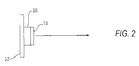
Figure 2 shows a construction of a light source for emitting white light. A
layer of
phosphor material 18 is provided on a blue LED 20, which in turn is mounted on
a heat sink 22.
The phosphor layer 18 is excited by the blue light generated by the LED 20 and
generates red
and green light. The phosphor is adjusted, usually by changing the thickness
of the phosphor
layer or the density of the phosphor deposit, such that the total output of
blue light from the LED,
and red and green light from the phosphor material 18, is white light.
- 5 -
CA 02879326 2015-01-16
WO 2014/014605 PCT/US2013/046492
Figure 3 shows an embodiment of a light source employing the blue LED 20 and
phosphor material 18 of Figure 2, but further including a recycling collar 24.
The recycling
collar 24 has a generally hemispherical shaped outer surface 26 which is
inwardly reflective and
an aperture 28 centered about the emission axis 30. In the manner shown, light
emitted from the
LED 20 and phosphor material 18 having a low emission angle relative to the
axis 30 passes
through the aperture as the output of the light source. Emitted light 32
having an emission angle
larger than a predetermined angle strikes the reflective surface 26 of the
recycling collar 24 and
reflected back toward the phosphor material 18. In another embodiment, not
shown, the
recycling collar 24 can have a dual parabolic shape.
In Figure 4, a laser 34, e.g., a blue laser, is mounted on a recycling collar
24a. The output
36 of the laser 34 is directed towards the phosphor material 18 to further
excite the phosphor
layer 18. The laser excitation increases the light output of the light source
and thus the
brightness of the system. More than one laser may be used for additional
brightness depending
upon the output required, the light-handling capability of the LED, the
capacity of the heat sink
22, and the lifetime requirement of the system. Alternatively, the laser 34
can be mounted
externally of the recycling collar 24a, in which case the output 36 is
directed at the phosphor
material 18 through a hole in the recycling collar 24a.
As an alternative to using an LED and phosphor material 18, the embodiment of
Figure 4
may employ merely a phosphor layer coated on a heat sink. In such alternative
embodiment, the
system will operate as purely a laser-stimulated system.
In yet another embodiment of Figure 4, the recycling collar 24a is not used,
in order to
lower the costs of the system.
- 6 -
CA 02879326 2015-01-16
WO 2014/014605 PCT/US2013/046492
Figure 5 also uses a blue LED coated with phosphor material as a white light
source 40.
The output of the light source is coupled to the input end 42 of a light pipe
44, which may be
straight or tapered (as shown). The output end 46 of the light pipe 44 is
coupled to a beam
splitter 48. An excitation laser 14 is positioned so that its output 50 is
directed onto the beam
splitter 48, at an angle of approximately 90 degrees relative to the central
axis 52 of the light pipe
44, so that it is reflected towards the light source 40. Light 54 generated by
the light source 40
extends in the general direction of the axis 52 and passes through the beam
splitter 48 to be
emitted as output light. Optionally, a portion of the output end 56 of the
beam splitter 48 may be
coated with a reflective layer 58 to reflect and recycle a portion of the
output light back to the
light source 40 to increase the brightness of the output.
As an alternative to using an LED coated with phosphor, the light source 40
can be
replaced by a phosphor layer coated on the heatsink. A phosphor layer may also
be used which
produces colored light. For example, a green phosphor can be used to produce
green light. The
laser excitation increases the brightness of the green light thus generated.
Alternately, a red
phosphor may be used.
In the embodiment of Figure 6, a phosphor of different wavelength is used to
increase the
outputs of a certain color. For example, a green LED 60 with a wavelength of
540 nm is used
with a green phosphor layer 62 which is transparent to 540 nm light, but
absorbs ultra-violet
and/or blue light, such that the light source generates more green light.
Alternatively, a red
phosphor may be used when it is desired to increase the brightness of the red
output.
In general, any colored LED can be used, and the brightness can be increased
using the
excitation laser directed onto the transparent phosphor as describe above.
And, the selective
color brightness increase can be utilized in both the Figure 5 and Figure 6
embodiments.
- 7 -
CA 02879326 2015-01-16
WO 2014/014605 PCT/US2013/046492
Figure 7 schematically illustrates a typical DLP projector system where the
laser/LED
light source 64, which may be any of the embodiments described in Figures 2-6,
may be
employed. The output of the light source 64 passes through a color wheel 66, a
light tunnel 68,
and relay lenses 70 before entering a projector 72. The projector has a
conventional projection
engine 74, digital light processor imager 76, and output projection lenses 78
for projecting the
image on a screen (not shown). Insofar as DLP projection systems are well
known, they need
not be described further herein. Other projection systems using 3LCD and LCOS
can also be
used.
Figure 8 shows an alternative embodiment of a DLP projection system. Light
output
from a laser 34 is directed onto a beam splitter 48, as in Figure 5. The laser
light reflected
toward the phosphor material 18. Light generated by the LED 20 and phosphor
material 18 is
collimated by lenses 80. The collimated output passes through beam splitter 48
and enters a light
pipe 82 and passes through a color wheel 66. After passing through the color
wheel 66, the
output light passes through a lens array 70 into the projector 72, which
includes the engine 74,
DLP panel 76, and output lenses 78.
Figure 9 shows an embodiment of a light source driven by a laser input. The
laser 14 can
be UV or a blue laser made with semi-conductor materials, solid state, or
other laser materials
including gas lasers. The output 82 of the laser 14 passes through a lens 84
onto a selective flute
86, at an angle such that the output 82 is reflected towards a phosphor
material 18 coated on a
heat sink 12. The phosphor material 18 absorbs the laser radiation and emits
light of various
colors depending on the material used. For example, white, red, green, blue or
other colors can
be generated.
- 8 -
CA 02879326 2015-01-16
WO 2014/014605 PCT/US2013/046492
The phosphor material 18 is placed on top of a heat sink 12 such that the
temperature of
the phosphor remains low, which improves performance. One or more types of
phosphor
materials with different colors can be obtained. The heat sink 12 is given a
reflective surface
facing the recycling color 24, such that the laser light and emitted light
from the phosphor are all
directed toward the outlet aperture 28.
The output from the phosphor is usually Lambertian and contains a lot of high
angle
emission. The high angle emissions are reflected back to the phosphor material
18 by the
reflective collar 24. The collar can be spherical in shape in forming an
imaging device, imaging
the high angle phosphor emissions back on the phosphor material 18. Low angle
emissions exit
through the aperture 28 and pass through a collimating lens 80. The output
then passes through
the selective filter 86, which transmits the light emitted by the phosphor and
reflects the light of
the laser. The output parallel beam 87 can also be focused on a small spot
using an optical
focusing lens 88.
Figure 10 shows an alternate configuration of the recycling collar 24b with a
parabolic
shape. Light emitted by the phosphor material 18 greater than a predetermined
angle relative to
the axial direction 52 is reflected by the collar 24b in a direction
perpendicular to the axial
direction, and reflected a second time, by an opposed surface, back to the
phosphor material 18.
Figure 11 shows another configuration of a recycling collar 24c with a
parabolic shape.
In this case, the phosphor material 18 is placed at the focus of the parabolic
reflector such that
the light is reflected back toward the heat sink 12 and perpendicular to the
heat sink 12. A
reflector 90 is positioned parallel to or on top of the heat sink 12 such that
the parallel beam is
reflected towards the parabolic reflector 24c and focused back on the phosphor
material 18 for
recycling.
- 9 -
CA 02879326 2015-01-16
WO 2014/014605 PCT/US2013/046492
Figure 12 shows an embodiment using either a tapered light pipe or a compound
parabolic concentrator (CPC) 92. Laser output 82 is directed at a selective
beam splitter 48 such
that the laser beam is reflected towards the tapered light pipe or CPC 92 onto
the phosphor
material 18. Light emitted by the phosphor is coupled into the light pipe 92,
passes through the
selective beam splitter 48, toward the outlet end 94 of the beam splitter 48.
The selective beam
splitter 48 has all six side faces polished such that it acts a waveguides,
with total internal
reflection occurring at the triangular faces of the prisms forming the beam
splitter.
The outlet end 94 of the beam splitter 48 is covered by an annular optical
reflector 96
having a central aperture 98 to allow low angle light to exit, while
reflecting and recycling higher
angle light. Optionally, a reflective polarizer, not shown, can be placed over
the output aperture
such that unused polarized light can be recycled too.
Figure 13 shows another embodiment of the invention, in which the selective
beam
splitter 48 is replaced by selective filter plate 100 such as the output beam
82 from the laser 14 is
reflected towards a tapered light pipe or CPC 92 toward the phosphor material
18. The output
light from the phosphor material 18 is transmitted through the light pipe 92
through the selective
filter plate 100. The output end 101 of the CPC or tapered light pipe is
covered by a reflective
coating 102 having a central aperture 104 for passing only light having an
angle less that a
predetermined angle relative to the axis.
Figure 14 shows another embodiment which employs multiple phosphor materials
18a,
18b. The areas M1 without phosphor can be coated with a reflective surface
such that recycled
light will be reflected back towards the output end of the CPC or tapered
light pipe 92.
Alternatively, portions of the input end of the light pipe 92 can be coated
with a reflective
surface, as shown at M2.
- 10 -
CA 02879326 2015-01-16
WO 2014/014605 PCT/US2013/046492
Figure 15 shows another embodiment in which a light pipe 104 is reverse
tapered such
that high angle emissions from the phosphor material 18 will be reflected back
to the phosphor
material 18 for recycling. In the case of a reverse tapered light pipe 104,
the outside surface
should be coated with a reflective coating to produce total internal
reflection.
Figure 16 shows a variant of Figure 15, in which the output of the reverse
tapered light
pipe or CPC 104 is the input to a second tapered light pipe or CPC 92. Such
system allows the
output face dimension and angle of light output to be adjusted.
The tapered light pipes or CPCs used in Figures 15 and 16 can be solid or
hollow. If a
solid CPC is used, the outside surface needs to be coated with a reflective
coating.
Figure 17 shows a laser excited phosphor system with a layer of phosphor
material 18 on
top of a heat sink 12. The phosphor material 18 can be a phosphor powder bound
by glue or
other binders, a ceramic phosphor, or a liquid phosphor.
A spherical recycling collar 24a is placed such that the center of curvature
is substantially
at the location of the phosphor material 18 such that light emitted by the
phosphor which does
not pass through the aperture 28 will be reflected back upon itself Part of
the light emitted by
the phosphor exits the aperture 28 of the recycling collar 24a forming the
output for the system.
The portion of light not exiting the aperture 28 will be reflected back to the
phosphor material 18
for recycling. Part of the light hitting the phosphor material will be re-
emitted and exit through
the aperture 28 as a system output, and part of such light will be reflected
back to the phosphor
material a second time by the recycling collar 24a.
The system of Figure 17 includes a plurality of excitation lasers 14, whose
output is
directed through small apertures I 1 1 in the recycling collar 24a toward the
phosphor materials
18, such that the laser beams can enter without loss.
-Ii -
CA 02879326 2015-01-16
WO 2014/014605 PCT/US2013/046492
An example of a laser source configuration is shown in Figure 18. In such
example, six
apertures 111 are provided uniformly around the recycling collar 24a at a
specified radius "r"
from the center axis "C." The number of lasers can be adjusted to provide the
needed total laser
power. For high efficiency operation, the apertures for the laser beams are
made small relative to
the size of the recycling collar such that a minimum amount of surface are for
recycling is
removed.
Figure 19 shows another configuration, in which the recycling collar 24c is
parabolic
such that two reflections occur when a high angle beam of light from the
phosphor material 18
strikes the recycling collar's internal surface. The first reflection
collimates the beam, in a
direction perpendicular to the output axis, and the second reflection focuses
the beam back to the
phosphor material 18. In this case the excitation laser 14, whose output
enters through an
aperture 111, can be oriented such that the entering laser beam 114 extends in
a direction
perpendicular to the center axis 52. The laser beam 114 will reflect off an
opposed interior wall
of the recycling collar 24c, and be directed toward the phosphor material 18.
As shown in Figure
20, when designing the locations of the apertures 111, it is important that
apertures are not
formed opposite one another. Preferably, a reflective coating 120 surrounds
the phosphor
material 18 to improve recycling.
Figure 21 shows another configuration using one or more laser sources 14 to
excite the
phosphor material 18. Multiple lenses 122, 124 are used to collect and
collimate the light emitted
by the phosphor material 18. Three laser sources 14 are placed outside the
region where most of
the collimated light from the phosphor material 18 passes, such that the laser
output 82 is
reflected by a mirror 126 towards the phosphor material 18. The mirror 126 is
preferably small,
to match the size of the laser beam 82. Thus, the amount of blockage is
minimal.
- 12 -
CA 02879326 2015-01-16
WO 2014/014605 PCT/US2013/046492
Figure 22 shows an example of a configuration with three laser sources 14 is
shown in
Figure 22, three lasers 14 and three small mirrors 126 are placed around the
edge of the output
beam. Depending on the exact wavelength under consideration, the mirrors can
be made with
dichroic coating such that it reflects the laser beam and transmits the
outputs emitted by the
phosphor material 18, reducing the blocking loss for the system.
Figure 23 shows various configurations of the phosphor material with (a)
phosphor
powder/glue 18a or a ceramic phosphor 18b on top of the heat sink 12; (b) a
phosphor suspended
in liquid in a container 18c; or (c) phosphor 18d on a wheel 130 rotated by a
motor 132 such that
the surface are is increased, reducing the effective areas, and increasing the
total power handling
capacity.
Figure 24 shows an embodiment of a lamp system which utilizes fluorescent cell
140,
containing a liquid and a fluorescent material, pumped by a light source 142.
The light source
142 is preferably a laser with a wavelength selected to be absorbed by the
fluorescent material
inside the liquid. The cell 140 is made of glass or some other type of
transparent material. The
fluorescent materials can be phosphors of various colors, dyes of various
colors, or other
fluorescent materials, e.g., phosphor powder. The fluorescent materials can be
soluble in the
liquid or suspended or colloidal. For a certain color requirement, a mixture
of several
fluorescent materials may be used. The filter 156 is designed to transmit the
excitation laser
light wavelength and reflects the fluorescent light emitted by the phosphor to
the output
direction.
In one example, the input light source 142 is a blue laser. The liquid is a
glycol or
silicone oil with a suspension of phosphor. The phosphor cell 140 is
constructed with two pieces
of flat glass and formed to have an inlet 144 and an outlet 146 at opposite
ends of the cell 140.
- 13 -
CA 02879326 2015-01-16
WO 2014/014605 PCT/US2013/046492
The thickness of the cell 140 can be adjusted such that part of the laser
light is absorbed and part
of it is transmitted, providing the required optical spectrum for the
particular application.
Liquid inside of the phosphor cell 140 is continuously circulated by tubing
148 and a
pump 150. A first section 148a of tubing connects a reservoir 152 with the
pump 150. A second
section 148b of tubing connects the pump to the inlet 144 of the cell 140. A
third section 148c of
tubing connects the outlet 146 of the cell 140 with a cooler 154. Finally, a
fourth section 148d of
tubing returns liquid from the cooler 152 back to the reservoir 150. The term
"tubing" is
intended to be construed broadly to refer to any suitable piping or other
conduit for circulating a
liquid under pressure.
Phosphor suffers aging from usage, and light emission efficiency will decrease
over time.
For such reason, the reservoir 152 is preferably connected by couplings or
connectors (not
shown) to the first section 148a and the fourth section 184d of tubing such
that the reservoir 152
may be disconnected and replaced. The reservoir 152 is preferably a cartridge
containing a
liquid and phosphor suspension, which can be replaced when needed in order to
restore the
output to the original value. When disconnected from the tubing sections 148a
and 148d, the
cartridge is preferably configured such that the input and output are ends are
automatically
closed to prevent liquid from escaping. If desired, the cooler 154 can also be
made part of the
cartridge, in which case the couplings are provided at the input of the cooler
154 and the outlet of
the reservoir 152.
The fluid capacity of the reservoir 152 and the amount of phosphor contained
therein can
be designed to provide a desirable length of useful life. Various sizes of
interchangeable
cartridges can be made available to offer the user a choice of useful lives.
- 14 -
CA 02879326 2015-01-16
WO 2014/014605 PCT/US2013/046492
The system of Figure 24 also employs a spherical, ellipsoidal, or other curved
recycling
collar 24 having a central outlet aperture 28 for emitting light having an
emission angle, relative
to the center axis, less than a predetermined amount, and for reflecting and
recycling light having
an emission angle greater than such amount.
The recycling collar limits the output divergence of the light, thus reducing
the etendue of
the system. Since a portion of the recycled light will exit through the
aperture 28, the output
brightness is increased. Depending on the type of liquid and fluorescent
materials used, optional
diffusers can be added to the front and/or rear of the fluorescent cell such
that the recycled light
can be scattered sufficiently to redirect some of the light toward the output.
These optional
diffusers may also be used with the other embodiments of the invention.
In yet another embodiment, in addition to the phosphor material, a suspension
of a
passive scattering powder, e.g., glass powder or glass beads, can be used to
scatter the blue laser
light such that some of the un-absorbed blue laser light will be outputted as
scattered as blue
light and not as a laser beam. This scattered blue laser light will be mixed
with the other color
light from the phosphor for the projection engine. This allows a controlled
amount of blue laser
light to be used as non-coherent blue light for the projection engine.
Figure 25 shows another embodiment of the light source with a fluorescent cell
140
having an inlet 144a and an outlet 146a. In Figure 25, the cell 140 is on top
of, or attached to, a
heat sink 12, which is used in place of, or to augment, the cooler 154 in
Figure 24. A reflective
coating or mirror 156 is placed at the back of the fluorescent cell 140 such
that the fluorescent
output is directed towards the recycling collar 24 (if used). In Figure 25,
the light source 142
directs light to a selective filter 158 which is angled to reflect laser light
back towards the
- 15 -
CA 02879326 2015-01-16
WO 2014/014605 PCT/US2013/046492
fluorescent cell 140. The selective filter 150 allows light 160 generated by
the fluorescent cell
140 to pass through the filter 150.
Figure 26 shows a recycling system using fluorescent cell 140 whose output is
coupled to
a straight light pipe 170. The outlet end 172 of the light pipe includes a
reflective surface 174
having an aperture 176 which is centered about the center axis to allow low
angle light beams
180 to exit the light pipe 170, while at the same time reflecting the
remaining light back towards
the inlet end 178 for recycling. Since the reflected light will be scattered
and redirected, the
brightness is increased.
Figure 27 is similar to Figure 26, except that a tapered light pipe 170a
(i.e., a light pipe
which tapers from its outlet 172a towards its inlet 178a) is used.
Figure 28 shows a recycling system using a recycling collar 24 and a light
source 142 and
selective filter 158 similar to Figure 25. The cell 140 is mounted on a heat
sink 12. A reflector
182 is positioned between the cell 140 and the heat sink 12. Instead of a
diffuser, the reflector
can be provided with a scattering surface enhancing the recycling mechanism.
The input light
source 142 will be placed at the output side of the cell 140 with light
reflected towards the cell
140 by the selective filter 158. The output light 184 generated by the cell
140 which exits the
aperture 28 passes through the selective filter 150 as the output of the
system.
Figure 29 shows a recycling configuration similar to Figures 26 and 27, with
the
transmissive fluorescent cell replaced by a reflective fluorescent cell 140.
Figure 30 shows a variation of Figure 29 in which a beam splitter 190, founed
by a
prism, replaces the selective filter 158. In this case, the selective beam
splitter is inside a solid
beam splitter six-sided body (which may be a cube or a rectilinear body in
which the sides have
other dimensions). All surfaces of the body are optically finished such that
light inside the cube
- 16 -
CA 02879326 2015-01-16
WO 2014/014605 PCT/US2013/046492
will encounter total internal reflection at some of the surfaces. As shown,
preferably there is a
gap between the ends of the light pipe 170, which may be straight or tapered
as shown, and the
cell 140 and beam splitter 190, respectively.
Figure 31 shows a projection system similar to Figure 7, except that the light
source is a
fluorescent cell 140. The size of the fluorescent cell 140 and the recycling
collar 24 are selected
such that the etendue of the recycling light source will match the etendue of
the projection engine
72. The ratio of the original etendue of the fluorescent cell 140 and the
etendue of the projection
system will detemtine the gain of the recycling system. Preferably, the light
source (cell 140)
produces white light.
Figure 32 shows a light source with three different colors, red "R," green
"G,", and blue
"B" combined into a single output using an X-cube prism 192. The output 194
can be used as the
light source for a projection engine or in spot light applications.
The foregoing description represents the preferred embodiments of the
invention.
Various modifications will be apparent to persons skilled in the art. All such
modifications and
variations are intended to be within the scope of the invention, as set forth
in the following
claims.
- 17 -