Note: Descriptions are shown in the official language in which they were submitted.
CA 02879705 2016-07-26
AIRCRAFT FUEL TANK FLAMMABILITY REDUCTION METHODS AND SYSTEMS
AND AIR SEPARATION METHODS USING MEMBRANES
TECHNICAL FIELD
The embodiments relate to methods and systems for reducing flammability in
aircraft fuel tanks using membranes and air separation methods using
membranes.
BACKGROUND
A variety of known systems exist with the purpose of reducing flammability in
aircraft fuel tanks. Such systems may be known by a number of designations
including, but
not limited to, On-Board Inert Gas Generation System (OBIGGS), Nitrogen
Generation
System (NGS), Flammability Reduction System (FRS), Fuel Tank lnerting System
(FTIS),
etc. However, a commonality among the systems involves reducing the oxygen
content of
fuel tank ullage by feeding inert gas into the fuel tank. Often, the systems
produce
nitrogen-enriched air (NEA) for the inert gas. Air with lower percent oxygen
is less
flammable.
lnerting systems used to produce nitrogen-enriched air may rely on pressure
swing
absorption and desorption from media as a separation mechanism or diffusion
through
polymer membranes as another separation mechanism to remove oxygen. In systems
with
polymer hollow fiber membranes, compressed air enters the bore of the polymer
hollow
fiber and oxygen permeates through the polymer hollow fiber walls. The oxygen
permeate
is collected and exhausted overboard. The remaining nitrogen-enriched
retentate flows
through the bore and is collected at the air separation module product gas
outlet for
distribution to aircraft fuel tanks. Unfortunately, service life of the air
separation module
and the system operating conditions may be limited by the polymers used in
construction
of the gas separation module. Accordingly, increased reliability of air
separation modules
is desirable.
SUMMARY
In accordance with one disclosed aspect there is provided an aircraft fuel
tank
flammability reduction method. The method involves feeding pressurized air
into a filter
1
CA 02879705 2016-07-26
containing a membrane, contaminants in the pressurized air including
hydrocarbons
containing six or more carbon atoms. The method also involves contacting the
membrane
with the air feed, permeating oxygen and nitrogen from the air feed through
the
membrane, and producing filtered air from the filter as a result of the
membrane removing
any hydrocarbons containing six or more carbon atoms to produce a total of
0.001 ppm
w/w or less. The method further involves feeding the filtered air into an air
separation
module (ASM) and producing nitrogen-enriched air from the air separation
module, and
feeding the nitrogen-enriched air into the fuel tank on board the aircraft.
The filter may exhibit a pressure drop across the membrane of less than 5
pounds/inch2 (psi).
The membrane may exhibits a property of resisting degradation due to exposure
to
the hydrocarbons containing six or more carbon atoms.
The membrane may include a hollow fiber membrane.
The ASM may include a hollow fiber membrane.
The ASM hollow fiber membrane may exhibit a susceptibility to degradation from
exposure to hydrocarbons containing six or more carbon atoms.
The method may involve operating a particulate filter that lacks a membrane
upstream of the filter containing a membrane.
In accordance with another disclosed aspect there is provided an aircraft fuel
tank
flammability reduction system. The system includes a source for air, a filter
configured to
receive an air feed from the air source, and a membrane in the filter, the
membrane being
configured to permeate oxygen and nitrogen from the air feed through the
membrane at a
pressure drop across the membrane of less than 5 pounds/inch2 (psi) and to
produce
filtered air from the filter as a result of the membrane removing hydrocarbons
containing
six or more carbon atoms. The system also includes an air separation module
(ASM)
configured to receive filtered air from the filter and to produce nitrogen-
enriched air from
the air separation module. The system further includes a fuel tank on board
the aircraft
and configured to receive the nitrogen-enriched air.
The air source may be configured to provide pressurized air.
The membrane may be configured to remove any hydrocarbons containing six or
more carbon atoms to produce a total of 0.001 ppm w/w or less.
2
CA 02879705 2016-07-26
The membrane may exhibit a property of resisting degradation due to exposure
to
the hydrocarbons containing six or more carbon atoms.
The membrane may include a hollow fiber membrane.
The ASM may include a hollow fiber membrane.
The ASM hollow fiber membrane may exhibit a susceptibility to degradation from
exposure to hydrocarbons containing six or more carbon atoms.
The system may include a particulate filter that lacks a membrane upstream of
the
filter containing the membrane.
In accordance with another disclosed aspect there is provided an air
separation
method. The method involves feeding pressurized air into a filter containing a
hollow fiber
membrane, contaminants in the pressurized air including hydrocarbons
containing six or
more carbon atoms and the hollow fiber membrane exhibiting a property of
resisting
degradation due to exposure to the hydrocarbons. The method also involves
contacting
the hollow fiber membrane with the air feed, permeating oxygen and nitrogen
from the air
feed through the membrane, and producing filtered air from the filter as a
result of the
membrane removing hydrocarbons containing six or more carbon atoms. The filter
exhibits a pressure drop across the membrane of less than 5 pounds/inch2
(psi). The
method further involves feeding the filtered air into an air separation module
(ASM)
containing a hollow fiber membrane and producing nitrogen-enriched air from
the air
separation module, the ASM hollow fiber membrane exhibiting a susceptibility
to
degradation from exposure to hydrocarbons containing six or more carbon atoms.
The filter membrane may remove any hydrocarbons containing six or more carbon
atoms to produce a total of 0.001 ppm w/w or less.
The method may involve reducing aircraft fuel tank flammability using the
nitrogen-
enriched air.
The features, functions, and advantages that have been discussed can be
achieved
independently in various embodiments or may be combined in yet other
embodiments
further details of which can be seen with reference to the following
description and
drawings.
2A
CA 02879705 2015-01-19
WO 2014/107207
PCT/US2013/064380
Further, the disclosure comprises embodiments according to the following
clauses:
Clause 1. An aircraft fuel tank flammability reduction method comprising:
feeding pressurized air into a filter containing a membrane, contaminants in
the
pressurized air including hydrocarbons containing six or more carbon atoms;
contacting the membrane with the air feed, permeating oxygen and nitrogen from
the air feed through the membrane, and producing filtered air from the filter
as a result
of the membrane removing any hydrocarbons containing six or more carbon atoms
to
produce a total of 0.001 ppm w/w or less;
feeding the filtered air into an air separation module (ASM) and producing
nitrogen-enriched air from the air separation module; and
feeding the nitrogen-enriched air into the fuel tank on board the aircraft.
Clause 2. The method of clause 1 wherein the filter exhibits a pressure drop
across the membrane of less than 5 pounds/inch2 (psi).
Clause 3. The method of clause 1 wherein the membrane exhibits a property of
resisting degradation due to exposure to the hydrocarbons containing six or
more
carbon atoms.
Clause 4. The method of clause 1 wherein the membrane comprises a hollow
fiber membrane.
Clause 5. The method of clause 1 wherein the ASM comprises a hollow fiber
membrane.
Clause 6. The method of clause 5 wherein the ASM hollow fiber membrane
exhibits a susceptibility to degradation from exposure to hydrocarbons
containing six or
more carbon atoms.
Clause 7. The method of clause 1 further comprising operating a particulate
filter
that lacks a membrane upstream of the filter containing a membrane.
3
CA 02879705 2015-01-19
WO 2014/107207
PCT/US2013/064380
Clause 8. An air separation method comprising:
feeding pressurized air into a filter containing a hollow fiber membrane,
contaminants in the pressurized air including hydrocarbons containing six or
more
carbon atoms and the hollow fiber membrane exhibiting a property of resisting
degradation due to exposure to the hydrocarbons;
contacting the hollow fiber membrane with the air feed, permeating oxygen and
nitrogen from the air feed through the membrane, and producing filtered air
from the
filter as a result of the membrane removing hydrocarbons containing six or
more carbon
atoms, the filter exhibiting a pressure drop across the membrane of less than
5
pounds/inch2 (psi); and
feeding the filtered air into an air separation module (ASM) containing a
hollow
fiber membrane and producing nitrogen-enriched air from the air separation
module, the
ASM hollow fiber membrane exhibits a susceptibility to degradation from
exposure to
hydrocarbons containing six or more carbon atoms.
Clause 9. The method of clause 8 wherein the filter membrane removes any
hydrocarbons containing six or more carbon atoms to produce a total of 0.001
ppm w/w
or less.
Clause 10. The method of clause 8 further comprising reducing aircraft fuel
tank
flammability using the nitrogen-enriched air.
Clause 11. An aircraft fuel tank flammability reduction system comprising:
a source for air;
a filter configured to receive air feed from the air source;
a membrane in the filter, the membrane being configured to permeate oxygen
and nitrogen from the air feed through the membrane at a pressure drop across
the
membrane of less than 5 pounds/inch2 (psi) and to produce filtered air from
the filter as
a result of the membrane removing hydrocarbons containing six or more carbon
atoms;
an air separation module (ASM) configured to receive filtered air from the
filter
and to produce nitrogen-enriched air from the air separation module; and
a fuel tank on board the aircraft and configured to receive the nitrogen-
enriched
air.
4
CA 02879705 2015-01-19
WO 2014/107207
PCT/US2013/064380
Clause 12. The system of clause 11 wherein the air source is configured to
provide pressurized air.
Clause 13. The system of clause 11 wherein the membrane is configured to
remove any hydrocarbons containing six or more carbon atoms to produce a total
of
0.001 ppm w/w or less.
Clause 14. The system of clause 11 wherein the membrane exhibits a property
of resisting degradation due to exposure to the hydrocarbons containing six or
more
carbon atoms.
Clause 15. The system of clause 11 wherein the membrane comprises a hollow
fiber membrane.
Clause 16. The system of clause 11 wherein the ASM comprises a hollow fiber
membrane.
Clause 17. The system of clause 16 wherein the ASM hollow fiber membrane
exhibits a susceptibility to degradation from exposure to hydrocarbons
containing six or
more carbon atoms.
Clause 18. The system of clause 11 further comprising a particulate filter
that
lacks a membrane upstream of the filter containing the membrane.
BRIEF DESCRIPTION OF THE DRAWINGS
Some embodiments are described below with reference to the following
accompanying drawings.
Figures 1-3 show diagrams of fuel tank flammability reduction systems
according
to several embodiments.
DETAILED DESCRIPTION
Known aircraft fuel tank flammability reduction systems include a pressurized
air
source, an air separation module (ASM) configured to receive air feed from the
pressurized air source, and a fuel tank on board the aircraft configured to
receive
nitrogen-enriched air from the air separation module. Careful observation and
evaluation has shown that known pressurized air sources available on aircraft,
such as
5
CA 02879705 2015-01-19
WO 2014/107207
PCT/US2013/064380
engine bleed air, may be contaminated with various gases (including
hydrocarbon
gases) and liquid or solid aerosols of various sizes. Larger particles may
also be
present. More particularly, engine bleed air has been demonstrated to contain
residue
and degradation products from jet fuel, engine lubricating oil, hydraulic
fluid, de-icing
agents, and other contaminants present in the atmosphere, on the ground, and
at
altitude. Predominant contaminants are hydrocarbons containing only hydrogen
and
carbon, but other hydrocarbons and other contaminants, such as aldehydes,
ketones,
acids, and other gases may be present. Gas separation membranes, in general,
are
very susceptible to large hydrocarbon molecules, degradation products of which
were
further shown to contain six or more carbon atoms.
Air separation modules (ASMs) known for use in aerospace contain hollow fiber
membranes, which permeate oxygen through the membrane preferentially to
nitrogen.
The molecules that do not permeate are retained (retentate) and are called
nitrogen-
enriched air. However, in operating environments, ASMs exhibit loss of
performance
due to contamination and due to the natural relaxation for the fiber. In some
cases,
ASMs exhibit decreased service life. Contaminants can negatively affect the
polymer
performance and life in several ways. Fiber pores can be plugged by
particulates.
Liquids can coat membranes (form a boundary layer), cause polymer swelling, or
destroy membrane integrity. Polymer solvents could contribute to delamination
of a
polymer separation layer or within the separation layer and could lead to
compaction
(increase in separation layer thickness) or fiber deformation. Gasses can fill
up free
volume or, in significant levels, slowly accumulate to the membrane surface,
decreasing
permeation rate (especially heavy hydrocarbons with more than 15 carbon
atoms).
Gasses can cause plasticization or anti-plasticization at elevated
concentrations or can
reduce molecular weight of the polymer (break polymer chains). Additionally,
polymer
materials used to form hollow fiber membranes and other membranes may exhibit
a
susceptibility to degradation due to exposure to the hydrocarbons containing
six or more
carbon atoms.
Known aircraft fuel tank flammability reduction systems may include a
particulate
filter in an attempt to remove particles and/or include another filter, such
as a liquid
aerosols filter. However, known filters upstream of an ASM are not known to
remove
hydrocarbons containing six or more carbon atoms or small liquid or solid
aerosols.
6
CA 02879705 2015-01-19
WO 2014/107207
PCT/US2013/064380
To maximize the available pressure and minimize system weight and
maintenance, known aerospace systems utilize liquid and particulate filtration
and
account for the performance drop due to gaseous contamination (other than
ozone) in
the system design. Accordingly, it is not known for a filter upstream of an
ASM to
remove hydrocarbons containing six or more carbon atoms or small liquid or
solid
particles and also to exhibit a pressure drop of less than 5 pounds/inch2
(psi). In a
related manner, it is not known for such a filter to exhibit a high
permeability.
Further, although hollow fiber membranes are known for use in an ASM for
separation of oxygen from air, they are not known for use in other components
of an
aircraft fuel tank flammability reduction system, such as in a filter. It
follows that a hollow
fiber membrane in the ASM susceptible to contaminants received from the
pressurized
air source would also be susceptible to contaminants from the pressurized air
source
when functioning as a filter. Such a membrane in a filter may exhibit the same
limited
service life observed in the ASM. However, advances in material science for
membranes functioning in applications other than aerospace show promise in
exhibiting
characteristics suitable for use in the filter upstream of an ASM.
Specifically, new materials may resist degradation due to exposure to
hydrocarbons containing six or more carbon atoms. Although such materials
might not
function to effectively remove oxygen from air, they may function effectively
as a
membrane filter removing small liquid or solid particles and hydrocarbons
containing six
or more carbon atoms.
Consequently, a known material may be selected for use as a membrane in an
ASM and designed to effectively remove oxygen from air. Examples of
potentially
suitable known polymers for such materials include polyphenylene oxide (PPO),
polyimide, polysulfone, polycarbonate, and others, such as described in U.S.
Patents
No. 8,245,978 issued to Beers and 7,699,911 issued to Zhou. Additionally, a
material
different from that of the ASM membrane may be used in a filter upstream of
the ASM
as a membrane to effectively remove contaminants. Accordingly, the membrane in
the
filter may be less susceptible to degradation from exposure to hydrocarbons
containing
six or more carbon atoms compared to the membrane in the ASM. Even so, the
membrane in the ASM may be more effective in removing oxygen from air compared
to
the membrane in the filter. The different material in the membrane filter
might not be
previously known for such use. Contaminants remaining in the retentate of the
7
CA 02879705 2015-01-19
WO 2014/107207
PCT/US2013/064380
membrane filter may be collected for some later use or vented, either alone or
along
with the permeate (oxygen) from the ASM.
Although the embodiments herein are discussed as significant in use along with
a hollow fiber membrane ASM, they may also have applicability to other gas
separation
technologies. Also, although discussed herein in the context of aircraft fuel
tank
flammability reduction systems, other gas separation systems may benefit from
the
concepts in the described embodiments.
The described membrane filter may be placed downstream of a known filter. The
described membrane filter may benefit from the removal of particles and/or
liquid
aerosols performed by a known filter. Service life of the membrane filter may
thus be
increased if positioned downstream of a known particulate and/or liquid
aerosols filter.
Additionally, or instead of using a known filter, the membrane filter may
incorporate a
sweep gas feature to assist in clearing the membrane of accumulated
contaminants,
such as is generally known.
Using one or more of the embodiments described herein, the service life of an
ASM may be extended and system performance may increase by limiting membrane
performance degradation due to gaseous contamination. Accordingly, ASMs may be
sized smaller, saving weight and space. Currently, an ASM is often sized based
on an
end-of-life performance that accounts for performance degradation over time.
With
decreased degradation to the membrane due to contaminants described herein, a
given
surface area available for permeating oxygen may be maintained for a longer
time. The
longer life may decrease the surface area needed to reach the same service
life as
desired without the embodiments herein. Alternately, the same surface area may
be
used and an extended service life realized.
In known, non-aerospace applications, multiple filters may be staged to
provide
effective removal of contaminants upstream of an air separation system. The
multiple
filters add to system cost and maintenance time and may be eliminated or
reduced in
number relying on the embodiments herein. In non-aerospace applications,
activated
carbon is known for use as an adsorbent to remove unwanted hydrocarbons from
an air
source. However, activated carbon is considered unsuitable for use in
aerospace
applications given the need for regeneration and/or additional airplane
maintenance
cost of activated carbon filtration replacement. Additionally, membrane feed
pressure
may decrease due to the pressure drop through the activated carbon filter,
which
8
CA 02879705 2015-01-19
WO 2014/107207
PCT/US2013/064380
negatively impacts gas separation membrane performance. More weight and volume
of
activated carbon could be used to allow hydrocarbon removal without frequent
regeneration and/or replacement. Accordingly, unless a large volume of
activated
carbon is provided, servicing and usefulness of the activated carbon as a
hydrocarbon
removal medium is severely limited.
As a result, instead of focusing on new materials to replace membranes in
ASMs,
the embodiments herein take the approach of retaining known technology with
membrane materials susceptible to contaminants, but effective for air
separation.
Known technology may be combined with materials as a membrane filter
unsuitable for
02/N2 separation (such as, high 02 and N2 permeability and low selectivity),
but focused
on not permeating higher molecular weight contaminants. The benefits of
membrane
technology may be achieved in both respects.
In an embodiment, an aircraft fuel tank flammability reduction method includes
feeding pressurized air into a filter containing a membrane, contacting the
membrane
with the air feed, permeating oxygen and nitrogen from the air feed through
the
membrane, and producing filtered air from the filter. Contaminants in the
pressurized air
include hydrocarbons containing six or more carbon atoms. The filtered air is
produced
from the filter as a result of the membrane removing any hydrocarbons
containing six or
more carbon atoms to produce a total of 0.001 parts per million by
weight/weight (ppm
w/w) or less. The method includes feeding the filtered air into an air
separation module
and producing nitrogen-enriched air from the air separation module. The
nitrogen-
enriched air is fed into the fuel tank on board the aircraft.
By way of example, the filter may exhibit a pressure drop across the membrane
of less than 5 psi. The membrane may exhibit the property of resisting
degradation due
to exposure to the hydrocarbons containing six or more carbon atoms. As one
option,
the membrane may include a hollow fiber membrane, which may be polymer-based.
The ASM may also include a hollow fiber membrane. The hollow fiber membrane of
the
ASM may exhibit a susceptibility to degradation due to exposure to the
hydrocarbons
containing six or more carbon atoms. The method may further include operating
a
particulate filter that lacks a membrane upstream of the filter containing the
membrane.
The susceptibility to degradation may decrease permeability due to gaseous
contamination (other than ozone) and may vary by polymer. The higher the free
volume
of the polymer, the higher the performance, but also the higher the
permeability drop
9
CA 02879705 2015-01-19
WO 2014/107207
PCT/US2013/064380
due to contaminants because it includes more free volume to occupy. Using
membrane
filtration may increase the practicability of certain polymers in the ASM that
would
otherwise experience a permeability drop of about 20% or greater due to
natural
relaxation of the fiber and gaseous contamination. Without the described
embodiments
that include membrane filtration, such polymers may exhibit a high enough
performance
drop over the service life that it may not be practical to account for
permeability loss in
system sizing. Membrane polymers with a permeability drop that could
practically be
accounted for in the system design may still benefit from membrane filtration
as
discussed herein because the lower drop would positively affect the system
component
sizing.
In another embodiment, an air separation method includes feeding pressurized
air into a filter containing a hollow fiber membrane, contacting the hollow
fiber
membrane with the air feed, permeating oxygen and nitrogen from the air feed
through
the membrane and producing filtered air from the filter. Contaminants in the
pressurized
air include hydrocarbons containing six or more carbon atoms. The hollow fiber
membrane exhibits the property of resisting degradation due to exposure to the
hydrocarbons. The filtered air is produced from the filter as a result of the
membrane
removing hydrocarbons containing six or more carbon atoms. Further, the filter
exhibits
a pressure drop across the membrane of less than 5 psi. The method includes
feeding
the filtered air into an air separation module containing a hollow fiber
membrane and
producing nitrogen-enriched air from the air separation module. The ASM hollow
fiber
membrane exhibits a susceptibility to degradation from exposure to
hydrocarbons
containing six or more carbon atoms.
By way of example, the filter membrane removes any hydrocarbons containing
six or more carbon atoms to produce a total of 0.001 ppm w/w or less. Also,
the method
may include reducing aircraft fuel tank flammability using the nitrogen-
enriched air.
In a further embodiment, an aircraft fuel tank flammability reduction system
includes a source for air, a filter configured to receive air feed from the
air source, and a
membrane in the filter. The membrane is configured to permeate oxygen and
nitrogen
from the air feed through the membrane at a pressure drop across the membrane
of
less than 5 psi and to produce filtered air from the filter as a result of the
membrane
removing hydrocarbons containing six or more carbon atoms. The system includes
an
air separation module configured to receive filtered air from the filter and
to produce
CA 02879705 2015-01-19
WO 2014/107207
PCT/US2013/064380
nitrogen-enriched air from the air separation module. A fuel tank on board the
aircraft is
configured to receive the nitrogen-enriched air.
By way of example, the air source may be configured to provide pressurized
air.
The membrane may be configured to remove any hydrocarbons containing six or
more
carbon atoms to produce a total of 0.001 ppm w/w or less. The membrane may
exhibit
the property of resisting degradation due to exposure to the hydrocarbons
containing six
or more carbon atoms. As one option, the membrane may include a hollow fiber
membrane, which may be polymer-based. The ASM may also include a hollow fiber
membrane. The air separation module may include a hollow fiber membrane
exhibiting
a susceptibility to degradation from exposure to hydrocarbons containing six
or more
carbon atoms. The system may further include a particulate filter that lacks a
membrane
upstream of the filter containing the membrane.
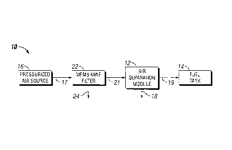
Figure 1 shows a diagram of a fuel tank flammability reduction system 10. In
system 10, a pressurized air source 16 provides air feed 17 to a membrane
filter 22.
Membrane filter 22 produces filtered air 21 and retentate gas 24, containing
contaminants removed from air feed 17. Membrane filter 22 may remove any
hydrocarbons containing six or more carbon atoms to produce a total of 0.001
ppm w/w
or less. Also, membrane filter 22 may exhibit a pressure drop across its
membrane of
less than 5 psi. Further, its membrane may exhibit the property of resisting
degradation
due to exposure to the hydrocarbons containing six or more carbon atoms. As an
example, the membrane may be a hollow fiber membrane.
A downstream air separation module 12 receives filtered air 21 and produces
nitrogen-enriched air 19 along with permeate gas 18. Air separation module 12
may
include a hollow fiber membrane. The membrane may exhibit a susceptibility to
degradation from exposure to hydrocarbons containing six or more carbon atoms.
Given
the removal of contaminants in retentate gas 24 by membrane filter 22, air
separation
module 12 is enabled to more effectively permeate oxygen through a membrane
(not
shown) and into permeate gas 18. Nitrogen-enriched air 19 is provided to a
fuel tank 14
for flammability reduction.
Figure 2 shows a diagram of a fuel tank flammability reduction system 20 that
includes all the elements of system 10, but further includes a particulate
filter 26.
Although not shown, particulate filter 26 may additionally function as a
liquid aerosols
filter or a separate liquid aerosols filter may be added to system 20 upstream
or
11
CA 02879705 2016-07-26
downstream of particulate filter 26. Particulate filter 26 provides filtered
air 23 to membrane
filter 22. In system 20, particulate filter 26 may prolong the service life of
membrane filter
22 by removing contaminants such as large particles and liquid aerosols that
may limit the
effective surface area of the membrane (not shown) in membrane filter 22.
Figure 3 shows a diagram of an aircraft fuel tank flammability reduction
system 30
that includes all the elements of system 10 shown in Figure 1, but
additionally includes a
heat exchanger 32. Often, known sources for pressurized air source 16 provides
air feed
17 at an elevated temperature that may be unsuitable for the membrane in air
separation
module 12 and/or the membrane in membrane filter 22. Heat exchanger 32 may be
used
to produce cooled air feed 34 to reduce heat damage to membranes in downstream
components. Alternatively, it is conceivable that pressurized air source 16
may provide air
feed 17 at a temperature limiting the performance of membranes in downstream
components because it is too cold. In such case, heat exchanger 32 may instead
produce
a heated air feed (not shown). It is further conceivable that the membrane in
membrane
filter 22 and the membrane in air separation module 12 might operate most
efficiently in
different temperature ranges. Accordingly, heat exchanger 32 may instead be
positioned
between membrane filter 22 and air separation module 12 or an additional heat
exchanger
may be provided to satisfy the temperature ranges of respective membranes.
Even further,
conceivably membrane filter 22 and air separation module 12 may include
membranes
operable at temperatures such that heat exchanger 32 may instead be located
downstream of air separation module to cool nitrogen-enriched air 19 before
being
provided to fuel tank 14.
Although systems 10, 20, and 30 discussed above each include fuel tank 14, it
is
noted consistent with the discussion above that nitrogen-enriched air 19 may
instead be
provided to a different component of a different system, such as an air
separation system.
Although Figures 1-3 show various possible embodiments of systems described
herein, it
will be appreciated that further combinations of the features in Figures 1-3
and other
features described herein are contemplated.
12
CA 02879705 2016-07-26
While specific embodiments have been described and illustrated, such
embodiments should be considered illustrative only and not as limiting the
invention as
defined by the accompanying claims.
13
CA 02879705 2015-01-19
WO 2014/107207
PCT/US2013/064380
TABLE OF REFERENCE NUMERALS FOR FIGURES
system
12 air separation module
14 fuel tank
5 16 pressurized air source
17 air feed
18 permeate gas
19 nitrogen-enriched air
system
10 21 filtered air
22 membrane filter
23 filtered air
24 retentate gas
26 particulate filter
15 30 system
32 heat exchanger
34 cooled air feed
14