Language selection

Search

Patent 2879801 Summary

Third-party information liability

Some of the information on this Web page has been provided by external sources. The Government of Canada is not responsible for the accuracy, reliability or currency of the information supplied by external sources. Users wishing to rely upon this information should consult directly with the source of the information. Content provided by external sources is not subject to official languages, privacy and accessibility requirements.

Claims and Abstract availability

Any discrepancies in the text and image of the Claims and Abstract are due to differing posting times. Text of the Claims and Abstract are posted:

  • At the time the application is open to public inspection;
  • At the time of issue of the patent (grant).
(12) Patent Application: (11) CA 2879801
(54) English Title: TACK SCREW
(54) French Title: PUNAISE
Status: Deemed Abandoned and Beyond the Period of Reinstatement - Pending Response to Notice of Disregarded Communication
Bibliographic Data
(51) International Patent Classification (IPC):
  • F16B 35/04 (2006.01)
(72) Inventors :
  • MALONEY, MICHAEL (United States of America)
(73) Owners :
  • PEM MANAGEMENT, INC.
(71) Applicants :
  • PEM MANAGEMENT, INC. (United States of America)
(74) Agent: SMART & BIGGAR LP
(74) Associate agent:
(45) Issued:
(86) PCT Filing Date: 2013-07-09
(87) Open to Public Inspection: 2014-01-23
Availability of licence: N/A
Dedicated to the Public: N/A
(25) Language of filing: English

Patent Cooperation Treaty (PCT): Yes
(86) PCT Filing Number: PCT/US2013/049639
(87) International Publication Number: WO 2014014699
(85) National Entry: 2015-01-21

(30) Application Priority Data:
Application No. Country/Territory Date
61/672,320 (United States of America) 2012-07-17

Abstracts

English Abstract

The present clinch screw can be secured through a hole in a sheet of metal by a simple press-in application like a tack pin. An undercut clinch feature on the screw shank just underneath the head and above a threaded bulb portion of the shank secures the screw to the sheet as material from the sheet cold-flows into the undercut. Simultaneously, sheet material also flows around and between the bulb threads which forms partial female threads in the sidewall of the sheet hole and provides added pull-out resistance. The screw can then be simply turned out to remove it. In doing so additional female threads are cut into the upper portion of the hole sidewall as the threaded bulb moves upward and then out of the hole. A re-useable threaded hole in the sheet is left behind.


French Abstract

L'invention porte sur une vis de sertissage, laquelle vis peut être fixée à travers un trou dans une feuille de métal par une simple application par pression, comme une punaise. Un élément de sertissage entaillé sur la tige de vis juste en dessous de la tête et au-dessus d'une partie de bulbe filetée de la tige fixe la vis à la feuille lorsqu'un matériau à partir de la feuille s'écoule à froid dans l'entaille. Simultanément, un matériau en feuille s'écoule également autour des filetages du bulbe et entre ceux-ci, ce qui forme des filetages femelle partiels dans la paroi latérale du trou de feuille et ce qui produit une résistance à l'arrachage supplémentaire. La vis peut ensuite être simplement tournée vers l'extérieur pour retirer celle-ci. Ce faisant, des filetages femelle additionnels sont découpés dans la partie supérieure de la paroi latérale de trou lorsque le bulbe fileté se déplace vers le haut, puis hors du trou. Un trou fileté réutilisable dans la feuille demeure.

Claims

Note: Claims are shown in the official language in which they were submitted.

6
CLAIMS
What is claimed is:
1. A metal-clinching tack screw for attachment to a metal sheet comprising:
a top most head being the largest diameter of the screw;
a shoulder extending axially downward from the head immediately below it,
said shoulder having a bottom surface for displacing material from a sheet of
metal
into which it is installed;
a barrel-shaped shank beginning directly beneath the shoulder and further
described as having sides of arcuate longitudinal cross-section which taper
inwardly
above and below a midsection bulb;
integral heilical screw threads on the outer surface of said bulb; and
an undercut located between the bottom of the shoulder and the bulb adapted
to receive material displaced by said shoulder bottom surface.
2. The screw of claim 1 wherein said shank further includes a tapered
bottom portion
extending downward from said bulb to an end of the screw.
3. The screw of claim 2 wherein the diameter of the bulb is less than the
diameter of the
shoulder.
4. An assembly of tightly joined first and second sheets face-to-face
comprising:
a top most head being the largest diameter of the screw;
a shoulder extending axially downward from the head immediately below it,
said shoulder having a bottom surface for displacing material from a sheet of
metal
into which it is installed;
a barrel-shaped shank beginning directly beneath the shoulder and further
described as having sides of arcuate longitudinal cross-section which taper
inwardly
above and below a midsection bulb;

7
integral heilical screw threads on the outer surface of said bulb;
an undercut located between the bottom of the shoulder and the bulb adapted
to receive material displaced by said shoulder bottom surface;
a first sheet having a first aperture sized to closely receive the shoulder of
said
screw; and
a second sheet having a second aperture in alignment with said first aperture
wherein the shank of the screw is rigidly secured to the second sheet by
capture of the
cold flow of material from the second sheet into the undercut and into the
threads of
the screw from sidewalls of the second aperture caused by axially pressing of
the
bottom of the shoulder into the second sheet.
5. The assembly of claim 4 wherein the aperture in the second sheet is a
blind hole.
6. The assembly of claim 4 wherein said screw threads are adapted to cut
corresponding
threads into an upper portion of said second sheet upon rotational removal of
the screw.
7. The assembly of claim 4 wherein the length of the shoulder is equal to
the sum of the
width of the top sheet and the depth of its penetration into the second sheet.
8. The assembly of claim 4 wherein the largest diameter of the shank bulb
is sized to
provide a slight interference fit with the second sheet sidewalls.

Description

Note: Descriptions are shown in the official language in which they were submitted.


CA 02879801 2015-01-21
WO 2014/014699
PCT/US2013/049639
1
TACK SCREW
RELATED APPLICATIONS
The present application is related to provisional patent application
61/672,320 entitled
"Tack Screw" filed on July 17, 2012 priority from which is hereby claimed.
FIELD OF THE INVENTION
The present invention relates to clinch-type fasteners. More specifically, it
relates to a
pressed-in tack pin that can be removed without significant damage to the
installation hole
due to a threaded bulb on the shank of the pin which enables the tack pin to
be removed by
turning it out.
BACKGROUND OF THE INVENTION
Tack pins are self clinching metallic fasteners that effectively tack a first
thin sheet to
a second sheet of metal by receiving the cold flow of metal from the second
sheet into an
undercut on the shank of the pin. Being harder than the panel into which they
are being
pressed tack pins are a strong method of attachment for thin metal assemblies.
For the same
depth of engagement, they can have greater pull out strength than a screw.
Another
advantage of tack pins is that they can be automatically installed by a
machine simply by
pressing the part on the head. No torque control or thread locking is
necessary since the tack
pin is retained by metal that has flowed into an undercut between its head and
shank.
A problem exists however because the attachment of standard tack pins is
permanent.
There is currently no means of a non-destructive, controlled removal of these
parts.
Removing a tack pin effectively destroys the installation hole which cannot be
re-used and re-
assembly requires that new installation holes be created. Therefore there is a
need in the art
for a press-in clinching fastener which can be non-destructively removed and
reinstalled.

CA 02879801 2015-01-21
WO 2014/014699
PCT/US2013/049639
2
SUMMARY OF THE INVENTION
According to one embodiment of the screw of my new invention, a thread is
added to
the bulb on the shank of a tack pin similar to the pin of US patent 8,297,899
which is hereby
incorporated by reference as though fully set forth. The screw can be pressed
in like a pin but
then unscrewed and re-used without destroying the receiving part. During
installation, metal
flows into the undercut of the part as well as into the thread valleys in the
bulb. The tack
screw can be removed by simple turning out via a variety of features such as
employing a hex
head and a complimentary tool driver.
When the tack screw is turned out, the thread on the shank bulb will push the
tack pin
upward with enough force to overcome the undercut clinch and also cut
additional threads
into the undercut material which has been pushed aside. A threaded hole in the
bottom sheet
which can be reused is created in the process. It will be appreciated from
these features that a
major advantage of the present tack screw is that it permits a non-destructive
rework of an
assembly.
The main features of the present tack screw for securing a top sheet to a
bottom sheet
include:
1) A head that retains a top sheet against a bottom sheet through aligned
installation
holes;
2) A shoulder to provide vertical clearance for the top sheet;
3) A displacer for clinching the screw into the bottom sheet that is provided
by the
bottom of the shoulder sized to the installation hole;
4) An undercut beneath the shoulder to be filled with displaced metal of the
bottom
sheet which retains the screw in the bottom sheet;
5) A shank including a threaded bulb which is sized relative to the
installation hole
in the bottom sheet to provide a slight interference fit; and

CA 02879801 2015-01-21
WO 2014/014699
PCT/US2013/049639
3
6) A tapered tip to aid in alignment of the tack pin when inserted into the
installation
holes.
According to one embodiment of the invention, the present tack screw is
installed
quickly by simply pressing downward on the head to force the shank of the
screw through
aligned apertures in the sheets to be joined. When metal flows from the bottom
sheet into the
undercut, it also flows into a helical thread on the shank bulb. Since there
is a filled undercut
above the bulb the tack screw of the invention is self- locking and will not
loosen. Because
there will be metal in the thread on the bulb the tack screw can be removed by
turning the
tack screw via the head in a direction that is counter to the direction of the
thread. In the
to process of removing the tack screw a usable thread will also be formed
in the top portion of
the installation hole previously forced into the undercut. Either the same
tack screw can be
re-installed by turning it into the now-threaded installation hole, or a new
screw can be used.
This performance capability is achieved by the properly selected hardness of
the screw and
the material of the attached sheets, and their respective dimensions.
In this respect, before explaining at least one embodiment of the invention in
detail, it
is to be understood that the invention is not limited in its application to
the details of
construction and to the arrangements of the components set forth in the
following description
or illustrated in the drawings. The invention is capable of other embodiments
and of being
practiced and carried out in various ways. Also, it is to be understood that
the phraseology
and terminology employed herein are for the purpose of description and should
not be
regarded as limiting.
As such, those skilled in the art will appreciate that the conception, upon
which this
disclosure is based, may readily be utilized as a basis for the designing of
other structures,
methods, and systems for carrying out the several purposes of the present
invention. It is

CA 02879801 2015-01-21
WO 2014/014699
PCT/US2013/049639
4
important, therefore, that the claims be regarded as including such equivalent
constructions
insofar as they do not depart from the spirit and scope of the present
invention.
BRIEF DESCRIPTION OF THE DRAWINGS
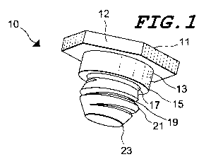
FIG. 1 is a bottom left isometric view of the invention.
FIG. 2 is a front cross-section view.
FIG. 3 is a front cross-section view.
FIG. 4 is a front cross-section view.
DESCRIPTION OF THE PREFERRED EMBODIMENT
Referring now to Figure 1, one embodiment of the tack screw 10 of the
invention will
to now be described according to its various features presented in order
from top to bottom.
The screw is a metal fastener with a hex-shaped head 11 which is the largest
diameter of the
fastener and is employed for pressed-in installation against a top sheet to
hold it against a
bottom sheet. The hex head 11 includes flats 12 on its sides to provide
drivable surfaces to
turn out the pin after installation if necessary. A shoulder 13 occurs
immediately below the
head. The length of the shoulder provides vertical clearance for the top sheet
and is
approximately equal to its width plus the depth of penetration into the bottom
sheet. As the
screw is pressed in, the bottom of the shoulder 15 displaces metal from the
bottom sheet into
an undercut 17 directly beneath the shoulder and also into the threads 19
below the undercut.
As the tack screw is pressed in, the undercut 17 gets filled with a cold flow
of metal from the
bottom sheet. This retains the pin in the bottom sheet and prevents any
loosening of the
threads 19. The shank of the screw is substantially barrel-shaped and includes
a generally
curved longitudinal profile that defines its bulbous shape. A bulb on the
midsection of the
shank tapers inwardly above and below its largest diameter and carries
integral threads along
its surface. The bulb is the largest diameter of the shank. At the bottom of
the tack pin is a
tapered tip 23 which aids in leading the part into the installation holes.

CA 02879801 2015-01-21
WO 2014/014699
PCT/US2013/049639
Referring now to Figure 2, a pre-installation alignment of the tack screw of
the
invention is shown. The screw 10 is installed by a punch 20 through aligned
apertures in the
top and bottom sheets, 31 and 33 respectively, which are supported on the
opposite side by an
anvil 35. The largest diameter of the shank bulb 21 is dimensioned to provide
a slight
5 interference fit with the sidewalls of the installation hole in the
bottom sheet.
Referring now to Figure 3, a fully installed tack screw is depicted. Here, the
head 11
of the tack screw captures the top sheet 31 against the bottom sheet 33. It is
retained to the
bottom sheet by the cold flow of metal from the aperture sidewalls of bottom
sheet into the
undercut 17 and grooves of the threads 19 caused by the pressing force of the
bottom of the
to shoulder. The sidewalls of the hole are thereby molded around the screw
threads and thus
become formed with a corresponding female thread profile which enables removal
of the pin
by turning it out. While the bottom sheet 33 is preferably metal the top sheet
31 may be of
any appropriate composition. As shown in Figure 4, the screw is now depicted
being
unscrewed which cuts additional female threads 30 into the upper portion of
the hole
previously occupied by the material from the undercut leaving re-useable
threads behind.
Therefore, the foregoing is considered as illustrative only of the principles
of the
invention. Further, since numerous modifications and changes will readily
occur to those
skilled in the art, it is not desired to limit the invention to the exact
construction and operation
shown and described, and accordingly, all suitable modifications and
equivalents may be
resorted to, falling within the scope of the invention.

Representative Drawing
A single figure which represents the drawing illustrating the invention.
Administrative Status

2024-08-01:As part of the Next Generation Patents (NGP) transition, the Canadian Patents Database (CPD) now contains a more detailed Event History, which replicates the Event Log of our new back-office solution.

Please note that "Inactive:" events refers to events no longer in use in our new back-office solution.

For a clearer understanding of the status of the application/patent presented on this page, the site Disclaimer , as well as the definitions for Patent , Event History , Maintenance Fee  and Payment History  should be consulted.

Event History

Description Date
Application Not Reinstated by Deadline 2016-07-11
Time Limit for Reversal Expired 2016-07-11
Deemed Abandoned - Failure to Respond to Maintenance Fee Notice 2015-07-09
Inactive: Cover page published 2015-03-03
Inactive: Notice - National entry - No RFE 2015-01-29
Application Received - PCT 2015-01-29
Inactive: First IPC assigned 2015-01-29
Inactive: IPC assigned 2015-01-29
National Entry Requirements Determined Compliant 2015-01-21
Application Published (Open to Public Inspection) 2014-01-23

Abandonment History

Abandonment Date Reason Reinstatement Date
2015-07-09

Fee History

Fee Type Anniversary Year Due Date Paid Date
Reinstatement (national entry) 2015-01-21
Basic national fee - standard 2015-01-21
Owners on Record

Note: Records showing the ownership history in alphabetical order.

Current Owners on Record
PEM MANAGEMENT, INC.
Past Owners on Record
MICHAEL MALONEY
Past Owners that do not appear in the "Owners on Record" listing will appear in other documentation within the application.
Documents

To view selected files, please enter reCAPTCHA code :


To view images, click a link in the Document Description column. To download the documents, select one or more checkboxes in the first column and then click the "Download Selected in PDF format (Zip Archive)" or the "Download Selected as Single PDF" button.

List of published and non-published patent-specific documents on the CPD .

If you have any difficulty accessing content, you can call the Client Service Centre at 1-866-997-1936 or send them an e-mail at CIPO Client Service Centre.


Document
Description 
Date
(yyyy-mm-dd) 
Number of pages   Size of Image (KB) 
Description 2015-01-21 5 195
Representative drawing 2015-01-21 1 7
Abstract 2015-01-21 1 62
Drawings 2015-01-21 2 51
Claims 2015-01-21 2 61
Cover Page 2015-03-03 1 38
Notice of National Entry 2015-01-29 1 205
Reminder of maintenance fee due 2015-03-10 1 111
Courtesy - Abandonment Letter (Maintenance Fee) 2015-09-03 1 171
PCT 2015-01-21 9 389