Note: Descriptions are shown in the official language in which they were submitted.
CA 02880091 2015-01-26
WO 2014/051846 PCT/US2013/052220
PIPE WRENCH WITH HOOK SHANK SPACER
RELATED APPLICATIONS
[0001] This application claims priority upon US utility application serial
number
13/626,132 filed September 25, 2012. The entire disclosure of that application
is
hereby incorporated by reference.
FIELD
[0002] The present subject matter relates to wrenches used for tightening
threaded members on a wide array of mechanical components, piping, and conduit
such as for example when engaging components and/or providing a sealed
connection.
BACKGROUND
[0003] Stillson wrenches (commonly known as "pipe wrenches") or other such
wrenches utilize a heel jaw secured to a handle and a movable hook jaw which
also
pivots to a limited extent about a point on the handle. Typically, the hook
jaw can be
selectively positioned relative to the heel jaw by rotating a threaded member
on the
wrench. The pivoting action of the hook jaw causes the hook jaw and heel jaw
to further
close as a rotational force is applied to the handle. Thus, gripping force and
torque are
simultaneously applied to a work piece.
[0004] Pipe wrenches typically used in the field utilize a threaded hook
jaw that
can be adjusted with a threaded member or nut to fit the size of the work
piece.
Nonetheless, the placement of the wrench on the work piece may be cumbersome
due
to the weight of the wrench or variations in the size of the work piece. Thus,
it is
common for an operator to rest the wrench on a shank portion of the hook jaw
before
force is applied to the handle. This practice still occurs even though it is
known to be an
improper use of a wrench as described in a publication, "Proper Use of Pipe
Wrenches"
by the Ridge Tool Company. Figure 1 illustrates this common improper placement
of a
wrench on a work piece. Specifically, a conventional pipe wrench 10 comprises
a
handle 20 having a lower jaw member 30, a sleeve portion 40 affixed to or
integrally
1
CA 02880091 2015-01-26
WO 2014/051846 PCT/US2013/052220
formed with the handle 20, a rotatable threaded member 50, and a movable upper
jaw
60. The upper jaw 60 includes a proximal end 62, an outer distal end 68, a
shank
portion 66 extending between the ends 62 and 68, and a threaded region 64. The
upper jaw 60 also includes an upper jaw member 70. As will be appreciated, the
distance between the lower jaw member 30 and the upper jaw member 70 can be
selectively adjusted by rotating the member 50. The upper jaw 60 and
specifically the
shank portion 66 defines an interior face 67. Upon positioning a work piece 5
between
the jaw members 30, 70, typically a user may rest the wrench 10 on the work
piece 5,
thereby resulting in contact between the shank face 67 and the work piece 5.
This
practice prevents the pivoting action of the hook jaw and limits the ability
of the jaws to
produce gripping force. As a result, the wrench may slip on the work piece
when torque
is applied. Additionally, the mechanical stress in the hook jaw is increased
due to a
transfer of force from the work piece to the shank of the hook. Failure of the
hook jaw
may result.
[0005] Accordingly, a need exists for a pipe wrench which is not
susceptible to
such problems with improper use and which provides an increased gripping force
on a
work piece positioned between its jaws upon application of torque to the
wrench.
SUMMARY
[0006] The difficulties and drawbacks associated with previously known
technology are addressed in the present products and methods as follows.
[0007] In one aspect, the present subject matter provides a wrench
comprising a
handle with a stationary lower jaw portion, and a movable upper jaw having a
depending shank. The shank includes a threaded region. The wrench also
comprises
a sleeve rigidly connected to the handle. The sleeve defines a channel sized
to
moveably receive at least a portion of the shank of the upper jaw. The wrench
also
comprises a rotatable member threadedly engaged with the threaded region of
the
shank of the upper jaw. The member is rotatably secured to at least one of the
handle
and the sleeve. Upon rotation of the member the distance between the lower jaw
and
the upper jaw is selectively adjusted. The wrench also comprises a deformable
member disposed along at least a portion of a face of the shank of the upper
jaw, to
thereby preclude contact between the shank and a work piece disposed between
the
lower jaw and the upper jaw.
2
CA 02880091 2015-01-26
WO 2014/051846 PCT/US2013/052220
[0008] In another aspect, the present subject matter provides an adjustable
wrench comprising a handle having a lower jaw portion and defining a channel
extending through the handle. The wrench also comprises an upper jaw having a
transversely extending threaded shank. The shank is movably disposed within
the
channel. The lower jaw, an inner face of the shank, and the upper jaw
collectively
define a work piece engaging region. The wrench also comprises a rotatable
member
threadedly engaged with the threaded shank of the upper jaw and movably
retained
with the handle. Upon rotation of the member the distance between the lower
jaw and
the upper jaw is selectively adjusted. And, the wrench also comprises a region
of
nonmetallic deformable material disposed along the inner face of the shank.
[0009] In yet another aspect, the present subject matter provides a wrench
comprising a handle with a stationary lower jaw portion. The wrench also
comprises a
movable upper jaw having a depending shank. The shank includes a threaded
region.
The wrench also comprises a sleeve rigidly connected to the handle. The sleeve
defines a channel sized to moveably receive at least a portion of the shank of
the upper
jaw. The wrench also comprises a rotatable member threadedly engaged with the
threaded region of the shank of the upper jaw. The member is rotatably secured
to at
least one of the handle and the sleeve. Upon rotation of the member the
distance
between the lower jaw and the upper jaw is selectively adjusted. The wrench
also
comprises a spacer member disposed along at least a portion of a face of the
shank of
the upper jaw and extending from at least one of the handle and the sleeve, to
thereby
preclude contact between the shank and a work piece disposed between the lower
jaw
and the upper jaw.
[0010] In still another aspect, the present subject matter provides a
method of
providing an increased gripping force on a work piece positioned between the
jaws of a
wrench upon application of torque to the wrench. The wrench includes (i) a
handle with
a stationary lower jaw portion, (ii) a movable upper jaw having a depending
shank, the
shank including a threaded region, (iii) a sleeve rigidly connected to the
handle, the
sleeve defining a channel sized to moveably receive at least a portion of the
shank of
the upper jaw, and (iv) a rotatable member threadedly engaged with the
threaded region
of the shank of the upper jaw, the member rotatably secured to at least one of
the
handle and the sleeve. Upon rotation of the member the distance between the
lower
jaw and the upper jaw is selectively adjusted. The method comprises attaching
a
spacer member to the wrench to preclude contact between the shank and a work
piece
disposed between the lower jaw and the upper jaw.
3
CA 02880091 2015-01-26
WO 2014/051846 PCT/US2013/052220
[0011] As will be realized, the subject matter described herein is capable
of other
and different embodiments and its several details are capable of modifications
in
various respects, all without departing from the claimed subject matter.
Accordingly, the
drawings and description are to be regarded as illustrative and not
restrictive.
BRIEF DESCRIPTION OF THE DRAWINGS
[0012] Figure 1 illustrates a typical yet undesirable placement of a work
piece
between the jaws of a conventional pipe wrench.
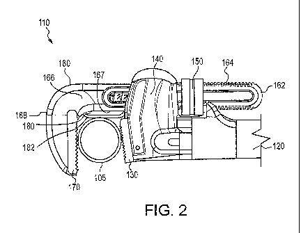
[0013] Figure 2 is a schematic view of a preferred embodiment wrench
having a
hook shank spacer in accordance with the present subject matter.
[0014] Figure 3 is a schematic view of another preferred embodiment wrench
having an alternate version of the hook shank spacer in accordance with the
present
subject matter.
[0015] Figures 4 and 5 are schematic views of yet another preferred
embodiment
wrench having another alternate version of the hook shank spacer in accordance
with
the present subject matter.
DETAILED DESCRIPTION OF THE EMBODIMENTS
[0016] The present subject matter provides a Stillson wrench or pipe
wrench
having a spacer, bumper, or other member positioned between a shank portion of
a
hook jaw and a work piece when disposed between the jaws of the wrench.
Depending
upon the particular configuration, the spacer or member may be formed from a
deformable material or a rigid material as described in greater detail herein.
The spacer
can be disposed either on the hook jaw, handle, or other component depending
upon
the type of wrench and/or application. With the addition and use of the
spacer, the
pivoting action of the hook is uninterrupted even if the wrench is rested on
the spacer
during initial engagement with a work piece. Thus, the problems associated
with the
previously noted improper field practice, i.e. lack of gripping force and
increased
mechanical stress, are avoided.
[0017] After provision of a pipe wrench having the noted spacer, or after
installation of the spacer on a pipe wrench, the spacer is rested on or
otherwise
contacted with the work piece thereby preventing direct contact between the
work piece
and the shank of the hook jaw. For embodiments of the present subject matter
utilizing
spacers formed from deformable materials, as force is applied to the handle,
the
deformable material of the spacer is compressed between the work piece and the
shank
4
CA 02880091 2015-01-26
WO 2014/051846 PCT/US2013/052220
of the hook jaw. Thus, the hook jaw pivots towards the heel jaw to produce
significantly
increased gripping force. Because the modulus of elasticity of the deformable
material
is much less than that of the material of the hook jaw, a small amount of
force is
transferred to the shank of the hook jaw as compared to the case in which the
shank of
the hook contacts the work piece directly. This same material property allows
the
deformable spacer to withstand large amounts of strain without damage.
[0018] The spacer or bumper is positioned on the wrench such that direct
contact
between the shank portion of the hook jaw and a work piece positioned between
the
jaws of the wrench, does not occur. The spacer or bumper can be affixed to one
or
more components of a wrench, or formed or manufactured with such component(s),
during manufacturing. Typically, the spacer or bumper is retained along at
least a
portion of the shank of the hook jaw. Alternatively, the spacer or bumper is
secured to a
region of the handle or to another component. In this alternate configuration,
the spacer
or bumper extends to a location relative to the hook jaw such that the spacer
prevents
contact between a work piece and the previously noted shank region of the hook
jaw.
[0019] The spacer or bumper can be formed from a ductile or deformable
material. Generally, a wide array of materials can be used for the spacer so
long as
they exhibit a modulus of elasticity or Young's modulus, which is less than
that of the
material typically forming the hook jaw, e.g. steel or aluminum and the
materials can
withstand the mechanical strain present in the application without deforming
plastically
or permanently. For example, in one configuration of a RIDGID model 36
straight
wrench produced by the Ridge Tool Company, a relative displacement of 0.032
inches
is observed between the shank of the hook and work piece. Thus, a nitrile
rubber with a
modulus of 0.025 ¨ 2 MPa is preferred for this particular configuration in
order to
minimize the stress of the component. In comparison, many steels exhibit a
Young's
modulus of approximately 200 GPa and many grades of aluminum exhibit a Young's
modulus of approximately 70 GPa. Materials can be selected for other
configurations
using the same approach; however, a Young's Modulus of 5 GPA or less is
generally
preferred for the deformable version of the spacer. Nonlimiting examples of
preferred
materials for use in the spacer or bumper of the present subject matter
include certain
polymeric materials such as nylon; polystyrene; polyesters such as
polyethylene
terephthalate (PET); polypropylene; polyethylenes including high density
(HDPE),
medium density, and low density (LDPE); TEFLON materials such as poly(tetra
fluoroethylene)(PTFE); rubber; and combinations thereof. For many
applications,
rubber is preferred. Generally, it is also preferred that the material
selected for the
CA 02880091 2015-01-26
WO 2014/051846
PCT/US2013/052220
spacer or bumper is also elastomeric. The material(s) selected for the spacer
or
bumper can be foamed and/or include various additives, fillers, and/or other
agents.
Typically, the deformable material used for the spacer is a non-metal
material.
[0020] Table 1
set forth below lists several materials which can be used for the
deformable spacer or guide. Table 1 also lists various other materials and
serves as a
guide for the selection of material(s) suitable for the spacer or bumper in
accordance
with the present subject matter.
Table 1 - Approximate Young's Modulus for Various Materials
Material GPa lbf/in2
(psi)
Rubber (small strain) <0.1
PTFE (Teflon) 0.5 75,000
Low density polyethylene 0.238 34,000
HDPE 0.8
Polypropylene 1.5-2
Polyethylene terephthalate (PET) 2-2.7
Polystyrene 3-3.5
Nylon 2-4 290,000-
580,000
Medium-density fiberboard 4 580,000
Pine wood (along grain) 9 1,300,000
Oak wood (along grain) 11
High-strength concrete 30
Hemp fiber 35
Magnesium metal (Mg) 45
Aluminum 69
10,000,000
Glass 50-90
Aramid 70.5-
112.4
Mother-of-pearl (nacre, largely calcium carbonate) 70
10,000,000
Tooth enamel (largely calcium phosphate) 83
12,000,000
Brass 100-125
Bronze 96-120
Titanium (Ti)
16,000,000
Titanium alloys 105-120 15,000,000-
17,500,000
Copper (Cu) 117
17,000,000
Glass-reinforced plastic (70/30 by weight fiber/matrix, 40-45
5,800,000¨
unidirectional, along grain) 6,500,000
Glass-reinforced polyester matrix 17.2 2,500,000
Carbon fiber reinforced plastic (50/50 fiber/matrix, 30-50
biaxial fabric)
Carbon fiber reinforced plastic (70/30 fiber/matrix, 181
26,300,000
unidirectional, along grain)
Silicon single crystal, different directions 130-185
Steel (ASTM-A36) 200
29,000,000
polycrystalline Yttrium iron garnet (YIG) 193
28,000,000
6
CA 02880091 2015-01-26
WO 2014/051846 PCT/US2013/052220
single-crystal Yttrium iron garnet (YIG) 200 30,000,000
Beryllium (Be) 287 42,000,000
Molybdenum (Mo) 329
Tungsten (W) 400-410
Silicon carbide (SiC) 450
Osmium (Os) 550 79,800,000
Tungsten carbide (WC) 450-650
Single-walled carbon nanotube 1,000+ 145,000,000+
Graphene 1000
[0021] Figure 2 illustrates a version of a preferred embodiment deformable
member and a wrench incorporating such member, in accordance with the present
subject matter. The wrench 110 comprises a handle 120 having a lower jaw
member
130, a sleeve portion 140 affixed or integrally formed with the handle 120, a
rotatable
threaded member 150, and a movable upper jaw 160. The upper jaw 160 defines a
proximal end 162, an outer distal end 168, a shank portion 166 extending
between the
ends 162 and 168, and a threaded region 164. The upper jaw 160 also includes
an
upper jaw member 170. The upper jaw 160 and specifically the shank portion 166
defines an interior face 167.
[0022] The wrench 110 also comprises a deformable spacer 180 disposed
along
the interior face 167. Upon positioning a work piece 105 between the jaw
members
130, 170, and positioning the work piece 105 toward the shank portion 166, the
work
piece 105 contacts the deformable spacer 180 instead of the interior face 167
of the
shank portion 166. Specifically, the work piece 105 contacts an outer face 182
of the
deformable member 180. The deformable member 180 is secured or otherwise
attached to the upper jaw 160 and/or the sleeve portion 140 (or other
component of the
lower jaw 130 or handle 120). The deformable member 180 can be secured or
attached
by temporary or permanent means. In this particular version, the deformable
member
180 is affixed to the interior face 167 of the shank portion 166 of the
movable upper jaw
160.
[0023] Figure 3 illustrates another version of a wrench 110a with a
deformable
spacer attached thereto. In this version, a deformable spacer 180a is
positioned about
the outer periphery of the upper jaw 160 and specifically about the shank
portion 166 to
contain the spacer within the assembly. The spacer 180a includes an outer
surface or
region 182a that is directed toward or faces a work piece 105 when positioned
between
the jaw members 130, 170. The wrench 110a includes the remaining components
7
CA 02880091 2015-01-26
WO 2014/051846 PCT/US2013/052220
having the same reference numbers as the wrench 110 previously described in
conjunction with Figure 2.
[0024] Figures 4 and 5 illustrate another version of a wrench 110b with a
spacer
attached thereto. The material for the spacer can be a rigid material. The
hook will
move closer to the work piece as torque is applied, but the hook will move
away from
the spacer attached to the handle as shown in Figure 5. More specifically, in
accordance with the present subject matter, a wrench 110b having a rigid
spacer 180b
is provided. Upon positioning the wrench 110b relative to a work piece 105,
the wrench
is placed upon and/or rested upon the work piece such that the spacer 180b
contacts
the work piece 105 as shown in Figure 4. This prevents direct contact between
the
shank 166 and the work piece 105. Figure 5 illustrates the wrench 110b and
work piece
105 after application of a force to the handle 120. The work piece 105 and the
upper
jaw 160 simultaneously pivot away from the spacer 180b and toward the lower
jaw 130
to the representative position shown in Figure 5. Thus, gripping force is
applied to the
work piece 105. Because the spacer 180b is positioned to maintain a gap or
space
between the shank portion 166 and the work piece 105, no force is transferred
between
the work piece 105 and the shank portion 166 of the upper jaw as force is
applied to the
handle 120. In this version, a rigid spacer 180b is attached to the sleeve
portion 140 or
the end of the handle 120 and extends toward the distal end 168 of the movable
upper
jaw 160. The spacer 180b includes an outer surface or region 182b that is
directed
toward or faces a work piece 105 when positioned between the jaw members 130,
170.
The spacer 180b extends alongside the interior face 167 (see Figure 2) of the
shank
portion 166, but is not affixed thereto. This configuration allows the face
167 to be
displaced relative to the spacer 180b as a user adjusts the distance between
the upper
and lower jaws. In this version of the present subject matter, the spacer 180b
is
described as formed from a rigid material. However, it will be appreciated
that the
spacer 180b could be formed from a ductile or deformable material also. The
term "rigid
material" as used herein refers to a material having a Young's modulus of 5
GPa or
greater. The wrench 110b includes the remaining components having the same
reference numbers as the wrench 110 previously described in conjunction with
Figure 2.
[0025] The present subject matter also provides methods of providing an
increased gripping force on a work piece when positioned between the jaws of a
wrench
such as a pipe wrench upon application of torque to the wrench. The method
comprises attaching a member to the wrench to thereby preclude contact between
the
shank of the hook jaw and a work piece disposed between the lower jaw and the
upper
8
CA 02880091 2015-01-26
WO 2014/051846 PCT/US2013/052220
jaw of the wrench. The member can be formed from a deformable material or from
a
rigid material. As previously described herein, for embodiments in which the
member is
attached directly to the shank region of an upper jaw such as in Figures 2 and
3, the
member is typically formed from a deformable member. For embodiments in which
the
member is attached to a handle, sleeve portion, or other region of a wrench
and
extends alongside to cover the shank region, the member can be formed from
either a
deformable material or a rigid material. Attachment of the member can be
accomplished in a wide array of techniques and strategies. For example, the
member
can be formed upon or about selected component(s) of the wrench prior to,
during,
and/or after assembly of the wrench. The member can also be incorporated
within
selected components of the wrench such as applied as a coating or layer. The
present
subject matter includes nearly any means by which the deformable member is
attached
to the wrench. Attachment of the deformable member can be either permanent or
temporary. However, for most applications it is contemplated that a permanent
attachment is preferred.
[0026] Additional details of components, assembly, and other aspects of
pipe
wrenches are provided in US Patents 95,744 to Stillson; 3,320,836 to Hagerman;
4,144,779 to Honick; 4,356,743 to Muschalek Jr.; 7,040,199 to Gregory; and
D657,213
to Pond et al.
[0027] The present subject matter can be implemented in a wide range of
wrenches and similar tools such as straight pipe wrenches (for example RIDGID
Straight Pipe Wrench model numbers 6 to 60 and aluminum model numbers 810 to
848
available from Ridge Tool), end pipe wrenches (for example RIDGID End Pipe
Wrench
model numbers E-6 to E-36 and aluminum model numbers E-910 to E-924), multi-
use
pipe wrenches (for example RIDGID Raprench model number 10), offset pipe
wrenches (for example RIDGID Heavy-Duty Offset Pipe Wrench model numbers 14
to
24 and aluminum model numbers 14 to 24), and compound leverage wrenches (for
example RIDGID Compound Leverage Wrenches model numbers S-2 to S-8A).
[0028] The present subject matter includes wrenches and similar tools
provided
with one or more deformable methods as described herein. The present subject
matter
also includes the deformable members by themselves or provided in a kit form
for
incorporation on used or previously purchased wrenches or similar tools. The
deformable or rigid members can be provided in a wide array of forms,
configurations,
colors, and so forth and are in no way limited to the particular versions
described herein.
9
CA 02880091 2015-01-26
WO 2014/051846 PCT/US2013/052220
[0029] Many other benefits will no doubt become apparent from future
application
and development of this technology.
[0030] All patents, applications, and articles noted herein are hereby
incorporated
by reference in their entirety.
[0031] As described hereinabove, the present subject matter overcomes
many
problems associated with previous strategies, systems and/or devices. However,
it will
be appreciated that various changes in the details, materials and arrangements
of
components, which have been herein described and illustrated in order to
explain the
nature of the present subject matter, may be made by those skilled in the art
without
departing from the principle and scope of the claimed subject matter, as
expressed in
the appended claims.