Note: Descriptions are shown in the official language in which they were submitted.
CA 02880327 2015-01-22
WO 2014/018003 PCT/US2012/047891
- 1 -
WELL DRILLING mumps WITH Ammo AND VIDEO INPUTS
FOR EVENT DETECTION
TECHNICAL FIELD
The present disclosure relates generally to equipment
utilized and operations performed in conjunction with a
subterranean well and, in an embodiment described herein,
more particularly provides well drilling methods with event
detection audio and video inputs.
BACKGROUND
It is desirable in drilling operations for certain
events to be identified as soon as they occur, so that any
needed remedial measures may be taken as soon as possible.
Events can also be normal, expected events, in which case it
would be desirable to be able to control the drilling
operations based on identification of such events.
Therefore, it will be appreciated that improvements
would be desirable in the art of event detection in drilling
operations.
CA 02880327 2015-01-22
WO 2014/018003 PCT/US2012/047891
- 2 -
BRIEF DESCRIPTION OF THE DRAWINGS
FIG. 1 is a schematic view of a well system which can
embody principles of the present disclosure.
FIG. 2 is a flowchart representing a method which
embodies principles of this disclosure.
FIG. 3 is a flowchart of an example of a parameter
signature generation process which may be used in the method
of FIG. 2.
FIG. 4 is a flowchart of an example of an event
signature generation and event identification process which
may be used in the method of FIG. 2.
FIG. 5 is a listing of events and corresponding event
signatures which may be used in the method of FIG. 2.
DETAILED DESCRIPTION
Representatively illustrated in FIG. 1 is a well
drilling system 10 and associated method which can embody
principles of this disclosure. However, it should be clearly
understood that the system 10 and method are merely one
example of an application of the principles of this
disclosure in practice, and a wide variety of other examples
are possible. Therefore, the scope of this disclosure is not
limited at all to the details of the system 10 and method
described herein and/or depicted in the drawings.
In the FIG. 1 example, a wellbore 12 is drilled by
rotating a drill bit 14 on an end of a drill string 16.
Drilling fluid 18, commonly known as mud, is circulated
downward through the drill string 16, out the drill bit 14
and upward through an annulus 20 formed between the drill
CA 02880327 2015-01-22
WO 2014/018003 PCT/US2012/047891
- 3 -
string and the wellbore 12, in order to cool the drill bit,
lubricate the drill string, remove cuttings and provide a
measure of bottom hole pressure control. A non-return valve
21 (typically a flapper-type check valve) prevents flow of
the drilling fluid 18 upward through the drill string 16
(e.g., when connections are being made in the drill string).
Control of wellbore pressure is very important in
managed pressure drilling, and in other types of drilling
operations. Preferably, the wellbore pressure is accurately
controlled to prevent excessive loss of fluid into the earth
formation surrounding the wellbore 12, undesired fracturing
of the formation, undesired influx of formation fluids into
the wellbore, etc. In typical managed pressure drilling, it
is desired to maintain the wellbore pressure just greater
than a pore pressure of the formation, without exceeding a
fracture pressure of the formation. In typical underbalanced
drilling, it is desired to maintain the wellbore pressure
somewhat less than the pore pressure, thereby obtaining a
controlled influx of fluid from the formation.
Nitrogen or another gas, or another lighter weight
fluid, may be added to the drilling fluid 18 for pressure
control. This technique is useful, for example, in
underbalanced drilling operations.
In the system 10, additional control over the wellbore
pressure is obtained by closing off the annulus 20 (e.g.,
isolating it from communication with the atmosphere and
enabling the annulus to be pressurized at or near the
surface) using a rotating control device 22 (RCD). The RCD
22 seals about the drill string 16 above a wellhead 24.
Although not shown in FIG. 1, the drill string 16 would
extend upwardly through the RCD 22 for connection to, for
example, a rotary table (not shown), a standpipe line 26,
CA 02880327 2015-01-22
WO 2014/018003 PCT/US2012/047891
- 4 -
kelly (not shown), a top drive and/or other conventional
drilling equipment.
The drilling fluid 18 exits the wellhead 24 via a wing
valve 28 in communication with the annulus 20 below the RCD
22. The fluid 18 then flows through drilling fluid return
lines 30, 73 to a choke manifold 32, which includes
redundant chokes 34 (one or more of which may be used at a
time). Backpressure is applied to the annulus 20 by variably
restricting flow of the fluid 18 through the operative
choke(s) 34.
The greater the restriction to flow through the choke
34, the greater the backpressure applied to the annulus 20.
Thus, wellbore pressure can be conveniently regulated by
varying the backpressure applied to the annulus 20. A
hydraulics model can be used to determine a pressure applied
to the annulus 20 at or near the surface which will result
in a desired bottom hole pressure, so that an operator (or
an automated control system) can readily determine how to
regulate the pressure applied to the annulus at or near the
surface (which can be conveniently measured) in order to
obtain the desired wellbore pressure.
Pressure applied to the annulus 20 can be measured at
or near the surface via a variety of pressure sensors 36,
38, 40, each of which is in communication with the annulus.
Pressure sensor 36 senses pressure below the RCD 22, but
above a blowout preventer (BOP) stack 42. Pressure sensor 38
senses pressure in the wellhead below the BOP stack 42.
Pressure sensor 40 senses pressure in the drilling fluid
return lines 30, 73 upstream of the choke manifold 32.
Another pressure sensor 44 senses pressure in the
drilling fluid injection (standpipe) line 26. Yet another
pressure sensor 46 senses pressure downstream of the choke
CA 02880327 2015-01-22
WO 2014/018003 PCT/US2012/047891
- 5 -
manifold 32, but upstream of a separator 48, shaker 50 and
mud pit 52. Additional sensors include temperature sensors
54, 56, Coriolis flowmeter 58, and flowmeters 62, 64, 66.
Not all of these sensors are necessary. For example,
the system 10 could include only two of the three flowmeters
62, 64, 66. However, input from the sensors is useful to the
hydraulics model in determining what the pressure applied to
the annulus 20 should be during the drilling operation.
Furthermore, the drill string 16 may include its own
sensors 60, for example, to directly measure bottom hole
pressure. Such sensors 60 may be of the type known to those
skilled in the art as pressure while drilling (PWD),
measurement while drilling (MWD) and/or logging while
drilling (LWD) systems. These drill string sensor systems
generally provide at least pressure measurement, and may
also provide temperature measurement, detection of drill
string characteristics (such as vibration, torque, rpm,
weight on bit, stick-slip, etc.), formation characteristics
(such as resistivity, density, etc.), fluid characteristics
and/or other measurements. Various forms of telemetry
(acoustic, pressure pulse, electromagnetic, etc.) may be
used to transmit the downhole sensor measurements to the
surface.
Additional sensors could be included in the system 10,
if desired. For example, another flowmeter 67 could be used
to measure the rate of flow of the fluid 18 exiting the
wellhead 24, another Coriolis flowmeter (not shown) could be
interconnected directly upstream or downstream of a rig mud
pump 68, etc. Pressure and level sensors could be used with
the separator 48, level sensors could be used to indicate a
volume of drilling fluid in the mud pit 52, etc.
CA 02880327 2012
WO 2014/018003 PCT/US2012/047891
- 6 -
Fewer sensors could be included in the system 10, if
desired. For example, the output of the rig mud pump 68
could be determined by counting pump strokes, instead of by
using flowmeter 62 or any other flowmeters.
Note that the separator 48 could be a 3 or 4 phase
separator, or a mud gas separator (sometimes referred to as
a "poor boy degasser"). However, the separator 48 is not
necessarily used in the system 10.
The drilling fluid 18 is pumped through the standpipe
line 26 and into the interior of the drill string 16 by the
rig mud pump 68. The pump 68 receives the fluid 18 from the
mud pit 52 and flows it via a standpipe manifold 70 to the
standpipe 26, the fluid then circulates downward through the
drill string 16, upward through the annulus 20, through the
drilling fluid return lines 30, 73, through the choke
manifold 32, and then via the separator 48 and shaker 50 to
the mud pit 52 for conditioning and recirculation.
Audio sensors 57 can be used to detect audio at any
location. For example, the audio sensors 57 could be
positioned in close proximity to rig equipment, so that
audio signals output by the rig equipment can be detected by
the audio sensors.
A microphone could be placed near the rig mud pump 68,
for example, to detect changes in the mud pumps' operation
due to certain events (such as a fluid influx or loss, the
beginning or end of a drill pipe connection, etc.). As
another example, a microphone could be placed near the choke
manifold 32 to detect changes in audio signals produced by
different fluids flowing at different flow rates through the
operative choke(s) 34. Any type, number or combination of
audio sensors 57 may be used in any locations (e.g., on a
rig at the surface, downhole, at a subsea location, etc.) to
CA 02880327 2015-01-22
WO 2014/018003 PCT/US2012/047891
- 7 -
detect audio signals from any sources, within the scope of
this disclosure.
Optical sensors 59 can be used to detect optical
signals at any location. For example, the optical sensors 59
could be positioned facing certain rig equipment, so that
optical signals output or reflected by the rig equipment can
be detected by the optical sensors.
A video camera could be directed at the standpipe 26,
for example, to detect movements of a kelly hose connected
thereto. As another example, a video camera (or merely a
photodiode, etc.) could be directed at a flare or the
separator 48 to detect optical changes due to different
fluids exiting the wellhead 24. Any type, number or
combination of optical sensors 59 may be used in any
locations (e.g., on a rig at the surface, downhole, at a
subsea location, etc.) to detect optical signals from any
sources, within the scope of this disclosure.
Note that, in the system 10 as so far described above,
the choke 34 cannot be used to control backpressure applied
to the annulus 20 for control of the bottom hole pressure,
unless the fluid 18 is flowing through the choke. In
conventional overbalanced drilling operations, such a
situation will arise whenever a connection is made in the
drill string 16 (e.g., to add another length of drill pipe
to the drill string as the wellbore 12 is drilled deeper),
and the lack of circulation will require that bottom hole
pressure be regulated solely by the density of the fluid 18.
In the system 10, however, flow of the fluid 18 through
the choke 34 can be maintained, even though the fluid does
not circulate through the drill string 16 and annulus 20,
while a connection is being made in the drill string. Thus,
pressure can still be applied to the annulus 20 by
CA 02880327 21312
WO 2014/018003 PCT/US2012/047891
- 8 -
restricting flow of the fluid 18 through the choke 34, even
though a separate backpressure pump may not be used.
Instead, the fluid 18 is flowed from the pump 68 to the
choke manifold 32 via a bypass line 72, 75 when a connection
is made in the drill string 16. Thus, the fluid 18 can
bypass the standpipe line 26, drill string 16 and annulus
20, and can flow directly from the pump 68 to the mud return
line 30, which remains in communication with the annulus 20.
Restriction of this flow by the choke 34 will thereby cause
pressure to be applied to the annulus 20.
As depicted in FIG. 1, both of the bypass line 75 and
the mud return line 30 are in communication with the annulus
via a single line 73. However, the bypass line 75 and the
mud return line 30 could instead be separately connected to
15 the wellhead 24, for example, using an additional wing valve
(e.g., below the RCD 22), in which case each of the lines
30, 75 would be directly in communication with the annulus
20. Although this might require some additional plumbing at
the rig site, the effect on the annulus pressure would be
20 essentially the same as connecting the bypass line 75 and
the mud return line 30 to the common line 73. Thus, it
should be appreciated that various different configurations
of the components of the system 10 may be used, without
departing from the principles of this disclosure.
Flow of the fluid 18 through the bypass line 72, 75 is
regulated by a choke or other type of flow control device
74. Line 72 is upstream of the bypass flow control device
74, and line 75 is downstream of the bypass flow control
device.
Flow of the fluid 18 through the standpipe line 26 is
substantially controlled by a valve or other type of flow
control device 76. Note that the flow control devices 74, 76
CA 02880327 21312
WO 2014/018003 PCT/US2012/047891
- 9 -
are independently controllable, which provides substantial
benefits to the system 10, as described more fully below.
Since the rate of flow of the fluid 18 through each of
the standpipe and bypass lines 26, 72 is useful in
determining how bottom hole pressure is affected by these
flows, the flowmeters 64, 66 are depicted in FIG. 1 as being
interconnected in these lines. However, the rate of flow
through the standpipe line 26 could be determined even if
only the flowmeters 62, 64 were used, and the rate of flow
through the bypass line 72 could be determined even if only
the flowmeters 62, 66 were used. Thus, it should be
understood that it is not necessary for the system 10 to
include all of the sensors depicted in FIG. 1 and described
herein, and the system could instead include additional
sensors, different combinations and/or types of sensors,
etc.
A bypass flow control device 78 and flow restrictor 80
may be used for filling the standpipe line 26 and drill
string 16 after a connection is made, and equalizing
pressure between the standpipe line and mud return lines 30,
73 prior to opening the flow control device 76. Otherwise,
sudden opening of the flow control device 76 prior to the
standpipe line 26 and drill string 16 being filled and
pressurized with the fluid 18 could cause an undesirable
pressure transient in the annulus 20 (e.g., due to flow to
the choke manifold 32 temporarily being lost while the
standpipe line and drill string fill with fluid, etc.).
By opening the standpipe bypass flow control device 78
after a connection is made, the fluid 18 is permitted to
fill the standpipe line 26 and drill string 16 while a
substantial majority of the fluid continues to flow through
the bypass line 72, thereby enabling continued controlled
CA 02880327 2015-012
WO 2014/018003 PCT/US2012/047891
- 10 -
application of pressure to the annulus 20. After the
pressure in the standpipe line 26 has equalized with the
pressure in the mud return lines 30, 73 and bypass line 75,
the flow control device 76 can be opened, and then the flow
control device 74 can be closed to slowly divert a greater
proportion of the fluid 18 from the bypass line 72 to the
standpipe line 26.
Before a connection is made in the drill string 16, a
similar process can be performed, except in reverse, to
gradually divert flow of the fluid 18 from the standpipe
line 26 to the bypass line 72 in preparation for adding more
drill pipe to the drill string 16. That is, the flow control
device 74 can be gradually opened to slowly divert a greater
proportion of the fluid 18 from the standpipe line 26 to the
bypass line 72, and then the flow control device 76 can be
closed.
Note that the flow control device 78 and flow
restrictor 80 could be integrated into a single element
(e.g., a flow control device having a flow restriction
therein), and the flow control devices 76, 78 could be
integrated into a single flow control device 81 (e.g., a
single choke which can gradually open to slowly fill and
pressurize the standpipe line 26 and drill string 16 after a
drill pipe connection is made, and then open fully to allow
maximum flow while drilling).
However, since typical conventional drilling rigs are
equipped with the flow control device 76 in the form of a
valve in the standpipe manifold 70, and use of the standpipe
valve is incorporated into usual drilling practices, the
individually operable flow control devices 76, 78 are
presently preferred. The flow control devices 76, 78 are at
times referred to collectively below as though they are the
CA 02880327 21312
WO 2014/018003 PCT/US2012/047891
- 11 -
single flow control device 81, but it should be understood
that the flow control device 81 can include the individual
flow control devices 76, 78.
Note that the system 10 could include a backpressure
pump (not shown) for applying pressure to the annulus 20 and
drilling fluid return line 30 upstream of the choke manifold
32, if desired. The backpressure pump could be used instead
of, or in addition to, the bypass line 72 and flow control
device 74 to ensure that fluid continues to flow through the
choke manifold 32 during events such as making connections
in the drill string 16. In that case, additional sensors may
be used to, for example, monitor the pressure and flow rate
output of the backpressure pump.
The use of a backpressure pump is described in
International Application No. PCT/US10/38586, filed 15 June
2010. That international application also describes a method
of correcting an annulus pressure setpoint during drilling.
In other examples, connections may not be made in the
drill string 16 during drilling, for example, if the drill
string comprises a coiled tubing. The drill string 16 could
be provided with conductors and/other lines (e.g., in a
sidewall or interior of the drill string) for transmitting
data, commands, pressure, etc. between downhole and the
surface (e.g., for communication with the sensors 60).
Methods of controlling pressure and flow in drilling
operations, including the use of data validation and a
predictive device, are described in International
Application No. PCT/US10/56433, filed 12 November 2010.
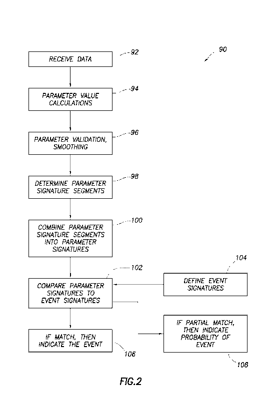
Referring additionally now to FIG. 2, a well drilling
method 90 which may be used with the system 10 of FIG. 1 is
schematically illustrated. However, it should be clearly
understood that the method 90 could be used in conjunction
CA 02880327 2015-01-22
WO 2014/018003 PCT/US2012/047891
- 12 -
with other systems in keeping with the principles of this
disclosure.
The method 90 includes an event detection process which
can be used to alert an operator if an event occurs, such
as, by triggering an alarm or displaying a warning if the
event is an undesired event (e.g., unacceptable fluid loss
to the formation, unacceptable fluid influx from the
formation into the wellbore, etc.), or by displaying
information about the event if it is a normal, expected or
desired event, etc. Well drilling methods incorporating
event detection are described in International Application
No. PCT/US09/52227, filed 30 July 2009, and well drilling
methods incorporating automated responses to event detection
are described in International Application No.
PCT/US11/42917, filed 5 July 2011.
An event can be a precursor to another event happening,
in which case detection of the first event can be used as an
indication that the second event is about to happen or is in
process of occurring. In addition, a series of events can
also provide an indication that another event is about to
happen. Thus, one or more prior events can be used as a
source of data for determining if another event will occur.
Many different events and types of events can be
detected in the method 90. These events can include, but are
not limited to, a kick (influx), partial fluid loss, total
fluid loss, standpipe bleed down, plugged choke, washed out
choke, poor hole cleaning (wellbore packed off about drill
string), downhole crossf low, wellbore washout, under gauged
wellbore, drilling break, ballooning while circulating,
ballooning while mud pump is off, stuck pipe, twisted off
pipe, back off, plugging of bit nozzle, bit nozzle washed
out, leak in surface processing equipment, rig pump failure,
CA 02880327 21312
WO 2014/018003 PCT/US2012/047891
- 13 -
backpressure pump failure, downhole sensor 60 failure,
washed out drill string, non-return valve failure, start of
drill pipe connection, drill pipe connection finished, etc.
In order to detect the events, drilling parameter
"signatures" produced in real time are compared to a set of
event "signatures" in order to determine if any of the
events represented by those event signatures is occurring.
Thus, what is happening now in the drilling operation (the
drilling parameter signatures) is compared to a set of
signatures which correspond to drilling events and, if there
is a match, this is an indication that the event
corresponding to the matched event signature is occurring.
Drilling properties (e.g., pressure temperature, flow
rate, etc.) are sensed by sensors, and output from the
sensors is used to supply data indicative of the drilling
properties. This drilling property data is used to determine
drilling parameters of interest.
Data can also be in the form of data from offset wells
(e.g., other wells drilled nearby or in similar lithologies,
conditions, etc.). Previous experience of drillers can also
serve as a source for the data. Data can also be entered by
an operator prior to or during the drilling operation.
A drilling parameter can comprise data related to a
single drilling property, or a parameter can comprise a
ratio, product, difference, sum or other function of data
related to multiple drilling properties. For example, it is
useful in drilling operations to monitor the difference
between the flow rate of drilling fluid injected into the
well (e.g., via the standpipe line 26 as sensed by flowmeter
66) and the flow rate of drilling fluid returned from the
well (e.g., via the drilling fluid return line 30 as sensed
by the flowmeter 67). Thus, a parameter of interest, which
CA 02880327 21012
WO 2014/018003 PCT/US2012/047891
- 14 -
can be used to define a part or segment of a signature can
be this difference in drilling properties (flow rate in -
flow rate out).
During a drilling operation, the drilling properties
are sensed over time, either continuously or intermittently.
Thus, data related to the drilling properties is available
over time, and the behavior of each drilling parameter can
be evaluated in real time. Of particular interest in the
method 90 is how the drilling parameters change over time,
that is, whether each parameter is increasing, decreasing,
remaining substantially the same, remaining within a certain
range, exceeding a maximum, falling below a minimum, etc.
These parameter behaviors are given appropriate values, '
and the values are combined to generate parameter signatures
indicative of what is occurring in real time during the
drilling operation. For example, one segment of a parameter
signature could indicate that standpipe pressure (e.g., as
measured by sensor 44) is increasing, another segment of the
parameter signature could indicate that pressure upstream of
the choke manifold (e.g., as measured by sensor 40) is
decreasing, another segment could indicate that the
amplitude of an audio signal detected by an audio sensor 57
is increasing, and another segment could indicate that the
wavelength of an optical signal detected by an optical
sensor 59 is within a certain range.
A parameter signature can include many (perhaps 20 or
more) of these segments. Thus, a parameter signature can
provide a "snapshot" of what is happening in real time
during the drilling operation.
An event signature, on the other hand, does not
represent what is occurring in real time during a drilling
operation. Instead, an event signature is representative of
CA 02880327 21312
WO 2014/018003 PCT/US2012/047891
- 15 -
what the drilling parameter behaviors will be when the
corresponding event does happen. Each event signature is
distinctive, because each event is indicated by a
distinctive combination of parameter behaviors.
As discussed above, an event can be a precursor to
another event. In that case, the event signature for the
first event can be a distinctive combination of parameter
behaviors which indicate that the second event is about to
(or at least is eventually going to) happen.
Events can be parameters, for example, in the
circumstance discussed above in which a series of events can
indicate that another event is going to happen. In that
case, the corresponding parameter behavior can be whether or
not the precursor event(s) have happened.
Event signatures can be generated prior to commencing a
drilling operation, and can be based on experience gained
from drilling similar wells under similar conditions, etc.
Event signatures can also be refined as a drilling operation
progresses and more experience is gained on the well being
drilled.
In basic terms, sensors are used to sense drilling
properties during a drilling operation, data relating to the
sensed properties are used to determine drilling parameters
of interest, values indicative of the behaviors of these
parameters are combined to form parameter signatures, and
the parameter signatures are compared to pre-defined event
signatures to detect whether any of the corresponding events
is occurring, or is substantially likely to occur.
Steps in an example of the event detection process are
schematically represented in FIG. 2 in flowchart form.
However, it should be understood that the method 90 can
include additional, alternative or optional steps as well,
CA 02880327 2015-012
WO 2014/018003 PCT/US2012/047891
- 16 -
and it is not necessary for all of the depicted steps to be
performed in keeping with the principles of this disclosure.
The method 90 may be performed with the system 10, or it may
be performed with any other well drilling system.
In a first step 92 depicted in the FIG. 2 example, data
is received. The data in this example is received from a
central database, such as an INSITE(TM) database utilized by
Halliburton Energy Services, Inc. of Houston, Texas USA,
although other databases may be used if desired.
The data typically is in the form of measurements of
drilling properties as sensed by various sensors during a
drilling operation. For example, the sensors 36, 38, 40, 44,
46, 54, 56, 57, 58, 59, 60, 62, 64, 66, 67, as well as other
sensors, will produce indications of various properties
(such as pressure, temperature, mass or volumetric flow
rate, density, resistivity, rpm, torque, weight, position,
audio, video, etc.), which will be stored as data in the
database. Calibration, conversion and/or other operations
may be performed for the data prior to the data being
received from the database.
The data may also be entered manually by an operator.
As another alternative, data can be received directly from
one or more sensors, or from another data acquisition
system, whether or not the data originates from sensor
measurements, and without first being stored in a separate
database. Furthermore, as discussed above, the data can be
derived from an offset well, previous experience, etc. Any
source for the data may be used, in keeping with the
principles of this disclosure.
In step 94, various parameter values are calculated for
later use in the method 90. For example, it may be desirable
to calculate a ratio of data values, a sum of data values, a
CA 02880327 21312
W02014/018003 PCT/US2012/047891
- 17 -
difference between data values, a product of data values,
etc. In some instances, however, the value of the data
itself is used as is, without any further calculation.
In step 96, the parameter values are validated and
smoothing techniques may be used to ensure that meaningful
parameter values are utilized in the later steps of the
method 90. For example, a parameter value may be excluded if
it represents an unreasonably high or low value for that
parameter, and the smoothing techniques may be used to
prevent unacceptably large parameter value transitions from
distorting later analysis. A parameter value can correspond
to whether or not another event has occurred, as discussed
above.
In step 98, the parameter signature segments are
determined. This step can include calculating values
indicative of the behaviors of the parameters. For example,
if a parameter has an increasing trend, a value of I may be
assigned to the corresponding parameter signature segment,
if a parameter has a decreasing trend, a value of 2 may be
assigned to the segment, if the parameter is unchanged, a
value of 0 may be assigned to the segment, etc. To determine
the behavior of a parameter, statistical calculations
(algorithms) may be applied to the parameter values
resulting from step 96.
Comparisons between parameters may also be made to
determine a particular signature segment. For example, if
one parameter is greater than another parameter, a value of
1 may be assigned to the signature segment, if the first
parameter is less than the second parameter, a value of 2
may be assigned, if the parameters are substantially equal,
a value of 0 may be assigned, etc.
CA 02880327 21312
WO 2014/018003 PCT/US2012/047891
- 18 -
In step 100, the parameter signature segments are
combined to make up the parameter signatures. Each parameter
signature is a combination of parameter signature segments
and represents what is happening in real time in the
drilling operation.
In step 102, the parameter signatures are compared to
the previously defined event signatures to see if there is a
match. Since data is continuously (or at least
intermittently) being generated in real time during a
drilling operation, corresponding parameter signatures can
also be generated in the method 90 in real time for
comparison to the event signatures. Thus, an operator can be
informed immediately during the drilling operation whether
an event is occurring.
Step 104 represents defining of the event signatures
which, as described above, can be performed prior to and/or
during the drilling operation. Example event signatures are
provided in FIG. 5, and are discussed in further detail
below.
In step 106, an event is indicated if there is a match
between an event signature and a parameter signature. An
indication can be provided to an operator, for example, by
displaying on a computer screen information relating to the
event, displaying an alert, sounding an alarm, etc.
Indications can also take the form of recording the
occurrence of the event in a database, computer memory, etc.
A control system can also, or alternatively, respond to an
indication of an event, as described more fully below.
In step 108, a probability of an event occurring is
indicated if there is a partial match between an event
signature and a parameter signature. For example, if an
event signature comprises a combination of 30 parameter
CA 02880327 21312
WO 2014/018003 PCT/US2012/047891
- 19 -
behaviors, and a parameter signature is generated in which
28 or 29 of the parameter behaviors match those of the event
signature, there may be a high probability that the event is
occurring, even though there may not be a complete match
between the parameter signature and the event signature. It
could be useful to provide an indication to an operator in
this circumstance that the probability that the event is
occurring is high.
Another useful indication would be of the probability
of the event occurring in the future. For example if, as in
the example discussed above, a substantial majority of the
parameter behaviors match between the parameter signature
and the event signature, and the unmatched parameter
behaviors are trending toward matching, then it would be
useful (particularly if the event is an undesired event) to
warn an operator that the event is likely to occur, so that
remedial measures may be taken if needed (for example, to
prevent an undesired event from occurring).
Referring additionally now to FIG. 3, a flowchart of
another example of the process of generating the parameter
signatures in the method 90 is representatively illustrated.
The process begins with receiving the data as in step 92
described above. Parameter value calculations are then
performed as in step 94 described above.
In step 110, preprocessing operations are performed for
the parameter values. For example, maximum and minimum
limits may be used for particular parameters, in order to
exclude erroneously high or low values of the parameters.
In step 112, the preprocessed parameter values are
stored in a data buffer. The data buffer is used to queue up
the parameter values for subsequent processing.
CA 02880327 2015-012
WO 2014/018003 PCT/US2012/047891
- 20 -
In step 114, conditioning calculations are performed
for the parameter values. For example, smoothing may be used
(such as, moving window average, Savitzky-Golay smoothing,
etc.) as discussed above in relation to step 96.
In step 116, the conditioned parameter values are
stored in a data buffer.
In step 118, statistical calculations are performed for
the parameter values. For example, trend analysis (such as,
straight line fit, determination of trend direction over
time, first and second order derivatives, etc.) may be used
to characterize the behavior of a parameter. Values assigned
to the parameter behaviors become segments of the resulting
parameter signatures, as discussed above for step 98.
In step 120, the parameter signature segments are
output to the database for storage, subsequent analysis,
etc. In this example, the parameter signature segments
become part of the INSITE(TM) database for the drilling
operation.
In step 100, as discussed above, the parameter
signature segments are combined to form the parameter
signatures.
Referring additionally now to FIG. 4, an example of a
flowchart for a process of identifying that an event has
occurred, or will occur, in the method 90 is
representatively illustrated. The process begins with step
122, in which an event signature database is configured. The
database can be configured to include any number of event
signatures to enable any number of corresponding events to
be identified during a drilling operation. Preferably, the
event signature database can be separately configured for
different types of drilling operations, such as
CA 02880327 21312
WO 2014/018003 PCT/US2012/047891
- 21 -
underbalanced drilling, overbalanced drilling, drilling in
particular lithologies, etc.
In step 124, a desired set of event signatures are
loaded into the event signature database. As discussed
above, any number, type and/or combination of event
signatures may be used in the method 90.
In step 126, the event signature database is queried to
see if there are any matches to the parameter signatures
generated in step 100. As discussed above, partial matches
may optionally be identified, as well.
In step 128, events are identified which correspond to
event signatures that match (or at least partially match)
any parameter signatures. The output in step 130 can take
various different forms, which may depend upon the
identified event. An alarm, alert, warning, display of
information, etc., may be provided as discussed above for
step 106. At a minimum, occurrence of the event could be
recorded, and in this example preferably is recorded, as
part of the INSITE(TM) database for the drilling operation.
Referring additionally now to FIG. 5, four example
event signatures are representatively tabulated, along with
parameter behaviors which correspond to the segments of the
signatures. In practice, many more event signatures may be
provided, and more or less parameter behaviors may be used
for determining the signature segments.
It should be clearly understood that the event
signatures depicted in FIG. 5 and the parameter behaviors
listed therein are merely for presenting examples of how
this disclosure's principles could be used in actual
practice. The scope of this disclosure is not limited to the
event signatures, or segments of those event signatures, as
representatively listed in FIG. 5. Different event
CA 02880327 2015-012
WO 2014/018003
PCT/US2012/047891
- 22 -
signatures, different parameter behaviors, different
signature segments and different combinations of segments,
etc., may be used in other examples within the scope of this
disclosure.
Note that each event signature is distinctive. Thus, a
kick (influx) event is indicated by a particular combination
of parameter behaviors, whereas a fluid loss event is
indicated by another particular combination of parameter
behaviors.
If, during a drilling operation, a parameter signature
is generated which matches (or at least partially matches)
any of the event signatures shown in FIG. 5, an indication
will be provided that the corresponding event is occurring.
If a parameter signature is generated which matches an event
signature to a predetermined level, or if the parameter
signature's segments are trending toward matching, then an
indication may be provided that the corresponding event is
substantially likely to occur. This can happen even without
any human intervention, resulting in a more automated,
precise and safe drilling environment.
In regard to the audio sensors 57, it is contemplated
that a general increase in volume would be expected if a
kick is occurring (e.g., due to increased flare burn rate,
mud pump 68 pumping harder, increased flow, etc.). A general
decrease in volume may be expected (at least initially) if a
fluid loss is occurring.
As another example, it is expected that a general
increase in volume will occur when a connection process is
started, and that a general decrease in volume will occur
when the connection process is completed.
Changes in pitch (frequency) of audio signals received
at, for example, pumps, motors, flares, etc., may also or
CA 02880327 2015-012
WO 2014/018003
PCT/US2012/047891
- 23 -
alternatively be used as parameter behaviors in event
signatures. For example, it is expected that the pitch of an
audio signal received at a mud pump motor will increase when
a kick is occurring.
With regard to the optical sensors 59, it is expected
that there will be more inconsistencies between, for
example, actual flow control device positions and those
positions as predicted by a hydraulics model, or as manually
input, when a kick is occurring. As another example, mud pit
52 volume as detected by an optical sensor 59 is expected to
differ from that volume as predicted by the hydraulics model
if a kick or loss is occurring. Inconsistencies in positions
of valves leading to the mud pit 52 (as detected by an
optical sensor 59) can also be used as an indicator of a
kick or loss.
Levels of particular light frequencies (e.g., infrared
and/or ultraviolet, etc.) detected at a flare can be used
for kick presence and kick size detection. In underbalanced
drilling operations, a rate of gas production can be
determined using such light frequency detection by optical
sensors 59.
Increased physical activity and movement of objects
(such as, a kelly hose connected in the standpipe line 26,
etc.) is expected to occur when a drill pipe connection is
started. This activity (and movement, positions of valves,
etc.) can be detected by the optical sensors 59. Decreased
activity and movement, and certain positions of elements
such as valves, are expected upon completion of the
connection process.
The event indications provided by the method 90 can be
used to control the drilling operation. For example, if a
kick event is indicated, the operative choke(s) 34 can be
CA 02880327 2015-012
WO 2014/018003 PCT/US2012/047891
- 24 -
adjusted in response to increase pressure applied to the
annulus 20 in the system 10. If fluid loss is detected, the
choke(s) 34 can be adjusted to decrease pressure applied to
the annulus 20. If a drill pipe connection is starting, the
flow control devices 81, 74 can be appropriately adjusted to
maintain a desired pressure in the annulus 20 during the
connection process, and when completion of the drill pipe
connection is detected, the flow control devices can be
appropriately adjusted to restore circulation flow through
the drill string 16 in preparation for drilling ahead.
These and other types of control over the drilling
operation can be implemented based on detection of the
corresponding events using the method 90 automatically and
without human intervention, if desired. In one example, a
control system such as that described in International
Application No. PCT/US08/87686 may be used for implementing
the control over the drilling operation.
In some embodiments, human intervention could be used,
for example, to determine whether the control over the
drilling operation should be implemented in response to
detection of events in the method 90. Thus, if an event is
detected (or if the event is indicated as being likely to
happen), a human's authorization may be required before the
drilling operation is automatically controlled in response.
As depicted in FIG. 1, a controller 84 (such as a
programmable logic controller or another type of controller
capable of controlling operation of drilling equipment) is
connected to a control system 86 (such as the control system
described in International Application No. PCT/US08/87686,
or as described in International Application No.
PCT/US10/56433). The controller 84 is also connected to the
flow control devices 34, 74, 81 for regulating flow injected
CA 02880327 2015-012
WO 2014/018003 PCT/US2012/047891
- 25 -
into the drill string 16, flow through the drilling fluid
return line 30, and flow between the standpipe injection
line 26 and the return line 30.
The control system 86 can include various elements,
such as one or more computing devices/processors, a
hydraulic model, a wellbore model, a database, software in
various formats, memory, machine-readable code, etc. These
elements and others may be included in a single structure or
location, or they may be distributed among multiple
structures or locations.
The control system 86 is connected to the sensors 36,
38, 40, 44, 46, 54, 56, 57, 58, 59, 60, 62, 64, 66, 67 which
sense respective drilling properties during the drilling
operation. As discussed above, offset well data, previous
operator experience, other operator input, etc., may also be
input to the control system 86. The control system 86 can
include software, programmable and preprogrammed memory,
machine-readable code, etc. for carrying out the steps of
the method 90 described above.
The control system 86 may be located at the wellsite,
in which case the sensors 36, 38, 40, 44, 46, 54, 56, 57,
58, 59, 60, 62, 64, 66, 67 could be connected to the control
system by wires or wirelessly. Alternatively, the control
system 86 could be located at a remote location, in which
case the control system could receive data via satellite
transmission, the Internet, wirelessly, or by any other
appropriate means. The controller 84 can also be connected
to the control system 86 in various ways, whether the
control system is locally or remotely located.
In one example, the control system 86 can cause one or
any number of the chokes 34 to close (e.g., increasingly
restrict flow of the fluid 18 through the return line 30) by
CA 02880327 2015-012
WO 2014/018003 PCT/US2012/047891
- 26 -
a predetermined amount automatically in response to the step
130 output indicating that a kick (influx) has occurred, or
is substantially likely to occur. For example, if the
parameter signature matches (or substantially matches) the
event signature for a kick, then the control system 86 will
operate the controller 84 to close the operative choke(s) 34
by the predetermined amount (e.g., a percentage of the
choke's operating range, such as 1%-10% of that range).
The predetermined amount could be preprogrammed into
the control system 86, and/or the predetermined amount could
be input, for example, via a human-machine interface. After
the choke(s) 34 have been closed the predetermined amount,
control over operation of the choke(s) 34 can be returned to
an automated system whereby a wellbore or standpipe pressure
set point is maintained (which set point may be obtained,
e.g., from a hydraulics model or manual input), the choke(s)
can be manually operated, or another manner of controlling
the choke(s) can be implemented.
In another example, the control system 86 can cause one
or any number of the chokes 34 to open (e.g., decrease
restriction to flow of the fluid 18 through the return line
30) by a predetermined amount automatically in response to
the step 130 output indicating that a fluid loss has
occurred, or is substantially likely to occur. For example,
if the parameter signature matches (or substantially
matches) the event signature for a fluid loss, then the
control system 86 will operate the controller 84 to open the
operative choke(s) 34 by the predetermined amount (e.g., a
percentage of the choke's operating range, such as 1%-10% of
that range).
The predetermined amount could be preprogrammed into
the control system 86, and/or the predetermined amount could
CA 02880327 2015-012
WO 2014/018003 PCT/US2012/047891
- 27 -
be input, for example, via a human-machine interface. After
the choke(s) 34 have been opened the predetermined amount,
control over operation of the choke(s) 34 can be returned to
the automated system whereby the wellbore or standpipe
pressure set point is maintained (which set point may be
obtained, e.g., from a hydraulics model or manual input),
the choke(s) can be manually operated, or another manner of
controlling the choke(s) can be implemented.
In another example, the control system 86 can provide
an alert or an alarm to an operator that a particular event
has occurred, or is substantially likely to occur. The
operator can then take any needed remedial actions based on
the alert/alarm, or can override any actions taken by the
control system 86 automatically in response to the step 130
output. If action has already been taken by the control
system 86, the operator can undo or reverse such actions, if
desired.
In another example, the control system 86 can switch
between maintaining a desired wellbore pressure to
maintaining a desired standpipe pressure in response to the
step 130 output indicating that an event has occurred, or is
substantially likely to occur. A technique by which a
control system can maintain a wellbore pressure is described
in International Application Nos. PCT/US10/38586 and
PCT/US10/56433, and a technique by which a control system
can maintain a standpipe pressure is described in
International Application No. PCT/US11/31767.
The control system 86 can switch between such wellbore
pressure set point and standpipe 26 pressure set point modes
automatically in response to the step 130 output indicating
that an event has occurred, or is substantially likely to
occur. For example, if a kick (influx) event is detected,
CA 02880327 2015-012
WO 2014/018003 PCT/US2012/047891
- 28 -
the control system 86 can switch from maintaining a desired
wellbore 12 pressure to maintaining a desired standpipe 26
pressure. This switch may actually be performed after
verifying that conditions are acceptable for making the
switch, and after providing an operator with an option (such
as, via a displayed alert) to initiate the switch.
In another example, the control system 86 can
automatically provide an operator (such as a driller) with
instructions or guidance for what remedial measures to take
in response to the step 130 output indicating that an event
has occurred or is substantially likely to occur. The
instructions or guidance may be provided by a local well
site display, and/or may be transmitted between the well
site and a remote location, etc.
In another example, the control system 86 can implement
a well control procedure automatically in response to the
step 130 output indicating that an event has occurred, or is
substantially likely to occur. The well control procedure
could include routing return flow of the fluid 18 to a
conventional rig choke manifold 82 and gas buster 88 (see
FIG. 1) designed for handling well control situations.
Alternatively, the well control procedure could include
the control system 86 automatically operating the choke
manifold 32 to optimally circulate out an undesired influx.
An example of automated operation of a choke manifold to
circulate out an undesired influx is described in
International Application No. PCT/US10/20122, filed 5
January 2010.
In another example, the control system 86 can
manipulate a choke 34 (e.g., alternately open and close the
choke a certain amount, etc.) automatically in response to
the step 130 output indicating that the choke is plugged, or
CA 02880327 2015-012
WO 2014/018003 PCT/US2012/047891
- 29 -
is substantially likely to become plugged. The choke 34
plugging event can be represented by an event signature
which, for example, includes a parameter segment indicating
increasing pressure differential across the choke. The
manipulation of the choke 34 automatically in response to
the step 130 output can potentially dislodge whatever has
plugged or is increasingly plugging the choke.
In another example, the control system 86 can switch
flow of the fluid 18 from one of the chokes 34 to another of
the chokes automatically in response to the step 130 output
indicating that one of the chokes has become plugged, washed
out, locked or otherwise compromised, or is substantially
likely to become so compromised. The switching from one
choke 34 to another can be performed progressively and
automatically, so that a desired wellbore pressure or
standpipe pressure can also be maintained by the control
system 86 during the switching.
The control system 86 can switch flow of the fluid 18
from one of the chokes 34 to another of the chokes
automatically in response to the step 130 output indicating
that the fluid 18 flow is out of, or is substantially likely
to become out of, an optimum operating range of one of the
chokes. The chokes 34 can have different trim sizes, so that
the chokes have different optimum operating ranges. When the
flow of the fluid 18 is outside of the optimum operating
range of the choke 34 being used to variably restrict the
flow, it can be beneficial to switch the flow to another of
the chokes having an optimum operating range which better
matches the flow.
The control system 86 can open an additional choke 34
automatically in response to the step 130 output indicating
that an operating range of the operative choke is exceeded,
CA 02880327 2015-01-22
WO 2014/018003 PCT/US2012/047891
- 30 -
or is substantially likely to be exceeded, by the flow of
the fluid 18. By increasing the number of operative chokes
34 through which the fluid 18 flows, the flow through each
choke is reduced, so that the operating range of each choke
is not exceeded.
In another example, the control system 86 can modify or
correct a pressure set point (e.g., received from a
hydraulics model) automatically in response to the step 130
output indicating that: a) a sensor (such as the sensor 60,
a pressure while drilling (PWD) tool, etc.) has failed or is
substantially likely to fail, b) the drill string 16 has
parted (e.g., twisted off, disconnected, backed off, etc.)
downhole or is substantially likely to do so, and/or c) an
influx or loss event has occurred or is substantially likely
to occur, making adjustment of fluid 18 density in the
wellbore desirable in models, such as the hydraulics model
and/or a well model. The control system 86 can operate the
controller 84 using the modified/corrected set point,
instead of the set point received from, e.g., the hydraulics
model. The control system 86 can update the hydraulics
and/or well model(s) with revised fluid 18 density based on
the detection of the fluid influx or loss event.
In another example, the control system 86 can
automatically communicate to the hydraulics and/or well
model(s) that an event has been detected. For example, if
the event is a failure of the sensor 60 (such as a PWD
sensor, etc.), the control system 86 can automatically
communicate this to the hydraulics model, which will cease
correcting the pressure set point based on actual
measurements from the sensor. As another example, if the
event is parting of the drill string 16, the control system
86 can automatically communicate this to the hydraulics
CA 02880327 2015-012
WO 2014/018003 PCT/US2012/047891
- 31 -
and/or well model(s), which will adjust a volume of the
annulus 20 and/or other parameters in the model(s).
In another example, the control system 86 can open one
or more of the previously inoperative chokes 34
automatically in response to the step 130 output indicating
that excessive pressure exists in the wellbore 12, or at
least upstream of the choke manifold 32. A maximum pressure
can be preprogrammed into the control system 86 so that, if
the maximum pressure is exceeded, one or more of the chokes
34 will be opened by the controller 84 to relieve the excess
pressure.
In another example, the control system 86 can divert
flow to a rig choke manifold 82, or another choke manifold
similar to the choke manifold 32, automatically in response
to the step 130 output indicating that a sealing element of
the RCD 22 has failed, or is substantially likely to fail.
The control system 86 could also automatically open the
choke(s) 34 a desired amount, to thereby relieve pressure
under the RCD 22.
In another example, the control system 86 can modify an
annulus 20 volume used by the hydraulics and/or well
model(s) automatically in response to the step 130 output
indicating that a floating rig is heaving. For example, the
control system 86 could receive indications of rig heave
from a conventional motion compensation system of the
floating rig. The annulus 20 volume can be
modified/corrected by the control system 86 automatically in
response to indications that the rig has risen or fallen,
thereby enabling the wellbore or standpipe pressure set
point to be updated based on the modified/corrected annulus
volume.
CA 02880327 2015-012
WO 2014/018003 PCT/US2012/047891
- 32 -
It may now be fully appreciated that the above
disclosure provides many benefits to the art of well
drilling and event detection during drilling operations. The
method 90 examples described above enable drilling events to
be detected accurately and in real time, so that appropriate
actions may be taken if needed. Audio and optical inputs to
the event detection process can be used to, for example,
monitor rig activities which produce audio and/or visual
signals. The audio and/or visual signals can be included in
drilling parameter signatures, which are compared to event
signatures.
A well drilling method 90 example described above can
comprise sensing at least one of audio signals and optical
signals; generating a parameter signature during a drilling
operation, the parameter signature being based at least in
part on the sensing; and detecting a drilling event by
comparing the parameter signature to an event signature
indicative of the drilling event.
The sensing step can include positioning at least one
audio sensor 57 proximate at least one source of the audio
signals. The source may be rig equipment, a rig mud pump 68,
and/or a choke manifold 32. Any audio source may be used,
within the scope of this disclosure.
The audio sensor 57 can comprise a microphone. Any
other type of audio sensor may be used, within the scope of
this disclosure.
The sensing step may include positioning at least one
optical sensor 59 proximate at least one source of the
optical signals. The source can include rig equipment, a
separator 48, and/or a standpipe 26.
Any optical source may be used, within the scope of
this disclosure. A component can be an optical source, even
CA 02880327 2015-012
WO 2014/018003 PCT/US2012/047891
- 33 -
if optical signals are merely reflected off of, or
transmitted through, the component.
The optical sensor 59 may comprise a video camera
and/or a photodiode. Any other type of optical sensor may be
used, within the scope of this disclosure.
The drilling event can comprise a start of a drill pipe
connection, a completion of a drill pipe connection, a fluid
influx, a fluid loss, and/or any of a wide variety of other
events (such as, choke plugging, pipe separation, etc.). The
event may be a precursor to another event. Any type of
drilling event can be detected, within the scope of this
disclosure.
A well drilling system 10 is also described above. In
one example, the system 10 comprises a control system 86
which compares a parameter signature for a drilling
operation to an event signature indicative of a drilling
event, the parameter signature being based at least in part
on an output of at least one sensor selected from a group
comprising audio and optical sensors 57, 59, and a
controller 84 which controls the drilling operation in
response to the drilling event being indicated by at least a
partial match between the parameter signature and the event
signature.
The at least partial match may indicate that the
drilling event has occurred, or that the drilling event is
substantially likely to occur.
Although various examples have been described above,
with each example having certain features, it should be
understood that it is not necessary for a particular feature
of one example to be used exclusively with that example.
Instead, any of the features described above and/or depicted
in the drawings can be combined with any of the examples, in
CA 02880327 2015-012
WO 2014/018003 PCT/US2012/047891
- 34 -
addition to or in substitution for any of the other features
of those examples. One example's features are not mutually
exclusive to another example's features. Instead, the scope
of this disclosure encompasses any combination of any of the
features.
Although each example described above includes a
certain combination of features, it should be understood
that it is not necessary for all features of an example to
be used. Instead, any of the features described above can be
used, without any other particular feature or features also
being used.
It should be understood that the various embodiments
described herein may be utilized in various orientations,
such as inclined, inverted, horizontal, vertical, etc., and
in various configurations, without departing from the
principles of this disclosure. The embodiments are described
merely as examples of useful applications of the principles
of the disclosure, which is not limited to any specific
details of these embodiments.
In the above description of the representative
examples, directional terms (such as "above," "below,"
"upper," "lower," etc.) are used for convenience in
referring to the accompanying drawings. However, it should
be clearly understood that the scope of this disclosure is
not limited to any particular directions described herein.
The terms "including," "includes," "comprising,"
"comprises," and similar terms are used in a non-limiting
sense in this specification. For example, if a system,
method, apparatus, device, etc., is described as "including"
a certain feature or element, the system, method, apparatus,
device, etc., can include that feature or element, and can
also include other features or elements. Similarly, the term
CA 02880327 2015-01-22
WO 2014/018003 PCT/US2012/047891
- 35 -
"comprises" is considered to mean "comprises, but is not
limited to."
Of course, a person skilled in the art would, upon a
careful consideration of the above description of
representative embodiments of the disclosure, readily
appreciate that many modifications, additions,
substitutions, deletions, and other changes may be made to
the specific embodiments, and such changes are contemplated
by the principles of this disclosure. For example,
structures disclosed as being separately formed can, in
other examples, be integrally formed and vice versa.
Accordingly, the foregoing detailed description is to be
clearly understood as being given by way of illustration and
example only, the spirit and scope of the invention being
limited solely by the appended claims and their equivalents.