Note: Descriptions are shown in the official language in which they were submitted.
APPARATUS FOR FLUID CONTROL DEVICE LEAK DETECTION
FIELD OF THE DISCLOSURE
10001] This patent relates generally to leak detection and, more specifically,
to apparatus for
fluid control device leak detection.
BACKGROUND
[0002] Fluid control devices implemented in hazardous and/or lethal
applications (e.g.,
chlorine and/or polysilicon production) may include bellows to prevent process
fluid from
leaking through a bonnet to the atmosphere. However, in time, these bellows
may leak. In
some instances. these Sensors may be used to detect a bellows leak in a fluid
control device.
SUMMARY
[0003] An example apparatus in accordance with the teachings of this
disclosure includes a
plurality of ports. One of the ports is to receive a supply pressure to drive
an actuator and
another of the ports is to be fluidly coupled to a purge port of a fluid
control device. The
apparatus includes a sensor to measure a value at the purge port and a
processor to compare
the value to a predetermined value or a previously measured value to identify
if the value is
outside of a predetermined threshold.
[0004] Another apparatus includes a plurality of ports. A first one of the
ports is to receive a
supply pressure to drive an actuator and a second one of the ports is to be
fluidly coupled to a
bonnet port of a fluid control device. A bellows positioned between a flow
aperture of the
fluid control device and the bonnet port is to substantially prevent process
fluid from flowing
to the bonnet port. The apparatus also includes a sensor to measure a pressure
value at the
bonnet port and a processor to compare the pressure value to a predetermined
pressure value
or a previously measured pressure value to determine if there is a leak in the
bellows.
[0005] Another example apparatus includes a plurality of ports. One of the
ports is to receive
a supply pressure to drive an actuator and another of the ports is to be
fluidly coupled to a
purge port of a fluid control device. The apparatus includes a sensor to
measure a value at
the purge port and a processor to determine if there is a leak in the fluid
control device based
on the measured value.
[0005a] According to another aspect, there is provided an apparatus including
a valve
controller having a housing and a plurality of ports defined by the housing,
one of the ports to
receive a supply pressure to drive an actuator and another of the ports to be
fluidly coupled to
a purge port of a fluid control device. The valve controller further includes
a sensor disposed
in the housing to measure a pressure value at the purge port, and a processor
to compare the
- I -
CA 2880400 2019-10-10
pressure value to a predetermined value or a previously measured value to
identify if the
pressure value is outside of a predetermined threshold.
[0005b] According to yet another aspect, there is provided an apparatus
including a valve
controller having a housing and a plurality of ports defined by the housing,
with a first one of
the ports to receive a supply pressure to drive an actuator and a second one
of the ports to be
fluidly coupled to a bonnet port of a fluid control device. A bellows
positioned between a
flow aperture of the fluid control device and the bonnet port to substantially
prevent process
fluid from flowing to the bonnet port. The valve controller further include a
sensor disposed
in the housing to measure a pressure value at the bonnet port and a processor
to compare the
pressure value to a predetermined pressure value or a previously measured
pressure value to
determine if there is a leak in the bellows.
[0005c] According to still another aspect, there is provided an apparatus
including a valve
controller, including a housing and a plurality of ports defined by the
housing, one of the
ports to receive a supply pressure to drive an actuator and another of the
ports to be fluidly
coupled to a purge port of a fluid control device. The valve controller
further includes a
sensor disposed in the housing to measure a pressure value at the purge port;
and a processor
to determine if there is a leak in the fluid control device based on the
measured pressure
value.
BRIEF DESCRIPTION OF THE DRAWINGS
100061 FIG. 1 depicts a known fluid control device.
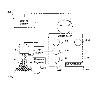
[0007] FIG. 2 depicts a fluid control device and an example controller in
accordance with the
teachings of this disclosure.
- la -
CA 2880400 2019-10-10
CA 02880400 2015-01-27
WO 2014/025717 PCMJS2013/053689
[0008] FIG. 3 is a schematic illustration of an example processor platform
that may be used
and/or programmed to implement any or all of the example methods are apparatus
disclosed
herein.
DETAILED DESCRIPTION
[0009] Certain examples are shown in the above-identified figures and
described in detail
below. In describing these examples, like or identical reference numbers are
used to identify
the same or similar elements. The figures are not necessarily to scale and
certain features and
certain views of the figures may be shown exaggerated in scale or in schematic
for clarity
and/or conciseness. Additionally, several examples have been described
throughout this
specification. Any features from any example may be included with, a
replacement for, or
otherwise combined with other features from other examples.
[0010] Fluid control devices implemented in hazardous and/or lethal
applications (e.g.,
chlorine and/or polysilicon production) may include bellows to prevent process
fluid from
leaking through a bonnet to the atmosphere. However, in time, these bellows
may leak.
Detecting such bellows leaks may be difficult without installing additional
air monitoring
components and/or exposing operators to hazardous conditions.
[0011] In some examples, bellows leaks may be detected at or around a valve
using air
monitoring equipment, pressure gauges and/or transmitters (e.g., air
monitoring components).
The air monitoring components may be coupled to a purge port of a valve bonnet
being
monitored. In operation, air quality and/or pressure measurements are
transmitted to a
control system that analyzes the measured values. The control system is remote
from the air
monitoring components. Based on the analysis, the control system may alert an
operator of a
potential bellows leak. While effective in monitoring bellows leaks, the logic
of such
systems is remote from the air monitoring components.
[0012] The examples disclosed herein monitor for bellows leaks and
automatically alert
and/or provide early detection and/or remote notification of such leaks using
a controller, an
electro-pneumatic controller and/or a digital valve controller (DVC). Such an
approach
eliminates the need for the additional air monitoring components while also
enhancing plant
safety by not exposing operators to the environment around the valve (e.g.,
the valve site)
being monitored.
[0013] In some examples, to monitor a valve for bellows leaks, a purge port of
a bonnet is
coupled to a pressure sensing port of a DVC having integral pressure sensing
capabilities. In
examples in which the valve is a single-acting valve, the pressure sensing
port may be an
unused port of the DVC that is configured to measure the purge port pressure.
In examples in
- 2 -
CA 02880400 2015-01-27
WO 2014/025717 PCT/US2013/053689
which the valve is a double-acting valve, the pressure sensing port may be a
port of the DVC
dedicated to measuring the purge port pressure and, thus, detecting bellows
leaks. Regardless
of the type of valve being monitored, the examples disclosed monitor bellows
leaks by
identifying pressure changes at a purge port. If the DVC determines that the
pressure
changes a particular amount, the DVC notifies an operator by conveying an
alert to a control
system and/or monitoring software. Additionally, the DVC may generate and/or
provide data
to generate a report including the date, the time, etc. of the bellows leak.
[0014] In some examples, to enable the DVC to detect a pressure change, a
profile is created
using diagnostic capabilities of the DVC that enables performance diagnostics
of the DVC to
monitor the valve (e.g., monitor the health of the valve). In some examples,
the profile is
configured and/or setup using monitoring software. The profile may specify a
minimum
bellows pressure change prior to sending an alert. However, in other examples,
firmware
used to implement the disclosed examples may include a bellows leak alert. In
some such
examples, a profile for the pressure change is not created (e.g., not set up
by an operator). In
any of the examples disclosed, the monitoring software may be AMS software
and/or
ValveLink Solo software of Emerson Process Management. While the above example
describes measuring pressure to identify a bellows leak, other parameters such
as air quality
may additionally or alternatively be measured and used to identify a leak.
[0015] In applications where the process pressure is over approximately 150
pounds per
square inch (psi), a pressure regulator may be installed between the purge
port and the DVC
to substantially prevent the process pressure from damaging the DVC. In some
examples, to
protect the DVC from process fluid, a pressure sensing diaphragm separates the
process fluid
from the DVC. The pressure sensing diaphragm may be integral to the DVC and/or
external
to the DVC.
[0016] FIG. 1 depicts a known fluid control device and/or valve 102 that
includes bellows
104 to substantially prevent process fluid from flowing to the atmosphere. The
bellows 104
is positioned between a flow path 106 and a purge port 108 of the fluid
control device 102.
However, in time, the bellows 104 may leak.
[0017] In operation, to monitor for bellows leaks, a sensor 110 measures a
value at the purge
port 108. The value is used by a control system 112 remote from the sensor 110
to determine
if the bellows 104 is leaking. In examples in which the measured value is an
air quality
value, the control system 112 may determine that the bellows 104 is leaking if
the measured
air quality value has changed and/or is outside of an acceptable and/or
predetermined air
quality value. In examples in which the measured value is a pressure value,
the control
- 3 -
CA 02880400 2015-01-27
WO 2014/025717 PCT/US2013/053689
system 112 may determine that the bellows 104 is leaking if the measured
pressure value is
higher than a predetermined pressure and/or if the pressure has risen a
particular amount. In
examples in which the sensor 110 is not coupled to the control system 112, the
fluid control
device 102 may be monitored for bellows leaks by an operator walking to the
valve site and
observing the sensor 110.
[0018] To control the position of the fluid control device 102, an electro-
pneumatic controller
114 is coupled to an actuator 115 via a first port 116 and coupled to an air
supply 118 via a
second port 120. In examples in which the actuator 115 is a double-acting
actuator, the
controller 114 is also coupled to the actuator 115 via a third port 122.
However, in examples
in which the actuator 115 is a single-acting actuator, as illustrated in FIG.
1, the third port 122
is unused. In operation, the controller 114 measures the position of the
actuator 115 and,
based on commands received from the remote control system 112, causes the
actuator 115 to
move to a particular position.
[0019] FIG. 2 depicts an example controller 200 with integrated bellows leak
detection
capabilities in accordance with the teachings of this disclosure. In
operation, to monitor for
bellows leaks, a first and/or air monitoring port 202 of the controller 200 is
coupled to the
purge port 108 to enable a sensor 204 of the controller 200 to measure a value
at the purge
port 108. The measured value is used by a processor 206 of the controller 200
to determine if
the bellows 104 is leaking. Thus, in contrast to known examples that use
remote processing
capabilities of the control system 112 (FIG. 1) and require additional
external monitoring
equipment, the controller 200 determines if the bellows 104 is leaking at the
valve site (i.e., a
local determination).
[0020] The sensor 204 may be a pressure sensor, an air quality sensor, etc. In
examples in
which the sensor 204 is an air quality sensor, the processor 206 may determine
that the
bellows 104 is leaking if the measured air quality value has changed and/or is
outside of an
acceptable and/or predetermined air quality value. In examples in which the
sensor 204 is a
pressure sensor, the control system 112 may determine that the bellows 104 is
leaking if the
measured pressure value is higher than a predetermined, threshold and/or fixed
pressure
and/or if the pressure has risen a particular amount over a particular amount
of time, for
example.
[0021] If the processor 206 determines that the bellows 104 is leaking, the
processor 206 may
automatically alert and/or notify a control system and/or monitoring system
208 and/or an
operator associated therewith. Such early notification of a bellows leak
enhances operator
safety because the fluid control device 102 may be used to control the flow of
hazardous
- 4 -
CA 02880400 2015-01-27
WO 2014/025717 PCT/US2013/053689
fluids and/or materials. Additionally or alternatively, the processor 206 may
generate and/or
provide data to generate a report associated with a detected bellows leak. In
some such
examples. the report may include a time stamp (e.g., date, time, etc.).
[0022] To substantially prevent excessive process pressure and/or process
fluid from
damaging the sensor 204 and/or the controller 200, a pressure regulator 210
and/or a pressure
sensing diaphragm may be fluidly coupled between the purge port 108 and the
sensor 204.
[0023] To control the position of the fluid control device 102, the controller
200 is coupled to
the actuator 115 via a second port 212 and coupled to the air supply 118 via a
third port 214.
In examples in which the actuator 115 is a double-acting actuator, the
controller 200 is also
coupled to the actuator 115 via a fourth port 216. While the controller 200
includes the
fourth port 216, in other examples, the controller 200 may not include the
fourth port 216. In
operation, the controller 200 measures the position of the actuator 115 and,
based on
commands received from the control system 208, causes the actuator 115 to move
to a
particular position.
[0024] FIG. 3 is a schematic diagram of an example processor platform P100
that may be
used and/or programmed to implement the controller 200 and/or any of the other
examples
disclosed herein. For example, the processor platform P100 can be implemented
by one or
more general purpose processors, processor cores, microcontrollers, etc.
[0025] The processor platform P100 of the example of FIG. 3 includes at least
one general
purpose programmable processor P105. The processor P105 executes coded
instructions
P110 and/or P112 present in main memory of the processor P105 (e.g., within a
RAM P115
and/or a ROM P120). The processor P105 may be any type of processing unit,
such as a
processor core, a processor and/or a microcontroller. The processor P105 may
execute,
among other things, the example methods and apparatus described herein.
[0026] The processor P105 is in communication with the main memory (including
a ROM
P120 and/or the RAM P115) via a bus P125. The RAM P115 may be implemented by
dynamic random-access memory (DRAM), synchronous dynamic random-access memory
(SDRAM), and/or any other type of RAM device, and ROM may be implemented by
flash
memory and/or any other desired type of memory device. Access to the memory
P115 and
the memory P120 may be controlled by a memory controller (not shown).
[0027] The processor platform P100 also includes an interface circuit P130.
The interface
circuit P130 may be implemented by any type of interface standard, such as an
external
memory interface, serial port, general purpose input/output, etc. One or more
input devices
P135 and one or more output devices P140 are connected to the interface
circuit P130.
- 5 -
CA 02880400 2015-01-27
WO 2014/025717 PCT/US2013/053689
[0028] As set forth herein, an apparatus includes a plurality of ports. One of
the ports is to
receive a supply pressure to drive an actuator and another of the ports to be
fluidly coupled to
a purge port of a fluid control device. The apparatus includes a sensor to
measure a value at
the purge port and a processor to compare the value to a predetermined value
or a previously
measured value to identify if the value is outside of a predetermined
threshold.
[0029] In some examples, the value being outside of the predetermined
threshold is
associated with a bellows leak in the fluid control device. In some examples,
the processor is
to generate an alert if the value is outside of the predetermined threshold.
In some examples,
the processor is to automatically communicate an alert to a remote monitoring
system based
on the processor identifying that the value is outside of the predetermined
threshold. In some
examples, the processor is to generate a report if the value is outside of the
predetermined
threshold. In some examples, the report includes a time stamp.
[0030] In some examples, the apparatus also includes a pressure regulator
fluidly coupled
between the purge port and the sensor. In some examples, the sensor includes a
pressure
sensing diaphragm assembly. In some examples, the value includes a pressure
value.
[0031] Another apparatus includes a plurality of ports. A first one of the
ports is to receive a
supply pressure to drive an actuator and a second one of the ports is to be
fluidly coupled to a
bonnet port of a fluid control device. A bellows positioned between a flow
aperture of the
fluid control device and the bonnet port is to substantially prevent process
fluid from flowing
to the bonnet port. The apparatus also includes a sensor to measure a pressure
value at the
bonnet port and a processor to compare the pressure value to a predetermined
pressure value
or a previously measured pressure value to determine if there is a leak in the
bellows.
[0032] In some examples, the processor is to generate an alert if the
processor determines
that if there is a leak in the bellows. In some examples, the processor is to
automatically
communicate an alert to a remote monitoring system based on the processor
determining that
there is a leak in the bellows. In some examples, the processor is to generate
a report based
on the processor determining that there is a leak in the bellows.
[0033] Another example apparatus includes a plurality of ports. One of the
ports is to receive
a supply pressure to drive an actuator and another of the ports is to be
fluidly coupled to a
purge port of a fluid control device. A bellows is positioned between a flow
aperture of the
fluid control device and the purge port to substantially prevent process fluid
from flowing to
the purge port. The apparatus also includes means for detecting a bellows leak
in the fluid
control device.
- 6 -
CA 02880400 2015-01-27
WO 2014/025717 PCT/US2013/053689
[0034] In some examples, the means for detecting a leak comprises a sensor to
measure a
value at the purge port. In some examples, the means for detecting a leak
comprises a
processor to compare the value to a predetermined value or a previously
measured value to
determine if there is a leak.
[0035] Another example apparatus includes a plurality of ports. One of the
ports is to receive
a supply pressure to drive an actuator and another of the ports is to be
fluidly coupled to a
purge port of a fluid control device. The apparatus includes a sensor to
measure a value at
the purge port and a processor to determine if there is a leak in the fluid
control device based
on the measured value.
[0036] In some examples, the leak in the fluid control device is associated
with the measured
value being outside of a predetermined threshold. In some examples, the
processor is to
compare the measured pressure value to the predetermined threshold. In some
examples, the
measured value includes a pressure value.
[0037] Although certain example methods, apparatus and articles of manufacture
have been
disclosed herein, the scope of coverage of this patent is not limited thereto.
On the contrary,
this patent covers all methods, apparatus and articles of manufacture fairly
falling within the
scope of the appended claims either literally or under the doctrine of
equivalents.
- 7 -