Note: Descriptions are shown in the official language in which they were submitted.
CA 02880697 2015-01-23
WO 2014/022801
PCT/US2013/053478
ULTRASONIC SEALING OF PACKAGES
BACKGROUND OF THE INVENTION
[0001] Technical Field
[0002] The present invention relates to an apparatus and method for sealing
films.
[0003] Description of Related Art
[0004] Various materials can be sealed using ultrasonic energy. The process
typically involves vibrating a horn in close proximity to an anvil. Frictional
forces in the
material between the horn and the anvil provide the necessary heat for
sealing.
[0005] There are many disadvantages to using ultrasonic energy to seal two
films.
One problem is the lap seal. In many packages made of films, the seals
comprise varying
numbers of layers. As an example, the seal will comprise three layers at the
location of the
lap seal but only two layers elsewhere. If a proper amount of energy is used
for the two-layer
seal, then this is insufficient energy to seal at the lap seal. Likewise, if a
proper amount of
energy is used at the lap seal, then too much energy is applied to the seal
with only two layers
resulting in an inadequate seal. Consequently, it is desirable to provide a
method and
apparatus which can seal films having a variable number of layers.
1
CA 02880697 2015-10-05
BRIEF DESCRIPTION OF THE DRAWINGS
[0006] The invention itself, however, as well as a preferred mode of use,
further
objectives and advantages thereof, will be best understood by reference to the
following detailed
description of illustrative embodiments when read in conjunction with the
accompanying
drawings, wherein:
[0007] Figure 1 illustrates a front profile view of the sealing device in one
embodiment.
[0008] Figure 2 illustrates a front profile view of the sealing device
comprising slots in
one embodiment.
[0009] Figure 3 illustrates a front profile view of the sealing device
comprising a
plurality of horns in one embodiment.
[0010] Figure 4 illustrates a front profile view of the sealing device
comprising cooling
channels in one embodiment.
[0011] Figure 5 illustrates a side profile view of a sealing device comprising
features in
one embodiment.
[0012] Figure 6 illustrates a graph showing the peel data for various
embodiments.
[0013] Figure 7 illustrates a side profile view of a sealing device comprising
cutting
features in one embodiment.
[0014] Figure 8 illustrates a side profile view of a sealing device comprising
features in
one embodiment.
[0015] Figure 9 illustrates a perspective view of a sealing device comprising
a rotary
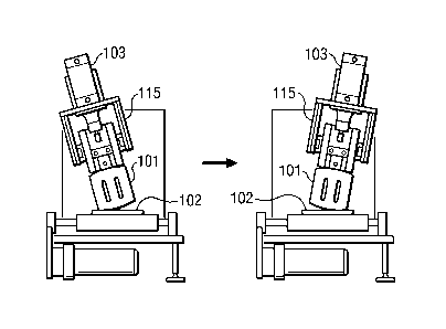
horn in one embodiment.
[0016] Figures 10A-10F illustrate perspective views of a floating horn in one
embodiment.
2
CA 02880697 2015-01-23
WO 2014/022801
PCT/US2013/053478
[0017] Figure 11A illustrates a top view of an integrated anvil in one
embodiment.
[0018] Figure 11B illustrates a side profile view of the anvil depicted in
Figure
11A.
3
CA 02880697 2015-01-23
WO 2014/022801
PCT/US2013/053478
DETAILED DESCRIPTION
[0019] Several embodiments of Applicants' invention will now be described with
reference to the drawings. Unless otherwise noted, like elements will be
identified by
identical numbers throughout all figures. The invention illustratively
disclosed herein
suitably may be practiced in the absence of any element which is not
specifically disclosed
herein.
[0020] Figure 1 illustrates a front profile view of the sealing device in one
embodiment. As depicted the sealing device comprises a horn 101, an anvil 102,
and a pair
of transducers 103a, b. In one embodiment a horn 101 is a bar of metal such as
titanium,
aluminum, steel, and combinations thereof which is dimensioned to be resonant
at a desired
frequency. As will be discussed below herein, the geometry of the horn 101 can
be altered to
affect the resonance, and accordingly the resultant amplitude, of the horn
101.
[0021] The sealing device, in one embodiment, comprises at least one
transducer
103a, b. As depicted in Figure 1 there are two transducers but virtually any
number of
transducers 103a, b may be utilized. The transducers 103a, b generate
ultrasonic energy in
the form of high frequency, typically low amplitude mechanical vibrations. In
one
embodiment the transducer 103a, b operates between 15 kHz and 75 kHz. In
another
embodiment the transducer 103a, b operates between 25 kHz and 40 kHz. The
vibratory
energy supplied by the transducer is applied to the horn 101 which causes the
horn 101 to
vibrate. The frictional forces caused between the vibrating horn 101 and the
anvil 102
produce heat which is used to seal the two work pieces together.
[0022] It should be noted that mechanical pressure is applied prior to and/or
during
and/or after the sealing of the work pieces to remove any interstitial air
gaps between the
work pieces and promote good thermal and acoustic contact. The pressure also
helps to hold
and help the work pieces fuse as they cool. As will be discussed in more
detail below,
4
CA 02880697 2015-01-23
WO 2014/022801
PCT/US2013/053478
pressure can also be used to change the energy dissipated into a work piece by
applying
different pressures across the weld joint so that the contact resistance
varies. The pressure
can be applied via servo motors, via hydraulic or pneumatic cylinders, or via
any device
known in the art to apply pressure. In one embodiment pressure from about 20
to about 250
psi is applied.
[0023] The anvil 102 comprises virtually any material. In one embodiment the
anvil 102 comprises the same material as the horn 101. In one embodiment the
anvil 102 is
stationary during the sealing.
[0024] Figure 1 illustrates an embodiment wherein the geometry of the horn 101
is
altered to affect the force felt by the work piece in specified portions. As
depicted the horn
101 comprises a non-uniform length and the anvil 102 comprises a uniform
length. A non-
uniform length refers to a horn 101 or anvil 102 which comprises at least one
area of
increased or decreased length relative to the remainder of the horn 102 or
anvil 102. The
length of the horn 101 is measured from the top of the horn 101 to the bottom
of the horn
101. As depicted the horn 101 comprises a protrusion 107 which extends beyond
the non-
raised portion 112 of the horn 101. By extending beyond the non-raised portion
112 of the
horn 101, the protrusion 107 results in increased force compared to the non-
raised portion
112 of the horn 101. While the protrusion 107 has been illustrated which
extends outward
beyond the non-raised portion 112, in other embodiments the protrusion 107
extends
inwardly. In such an embodiment, the non-raised portion 112 extends beyond the
protrusion
107. Such an inward protrusion 107 accounts for the increased thickness of the
seals. A
protrusion 107 results in a non-uniform gain across the face of the horn 101.
[0025] Figure 2 illustrates a front profile view of the sealing device
comprising slots
in one embodiment. Figure 2 illustrates a different manner in which a non-
uniform amplitude
can be obtained. Figure 2 comprises a uniform face but a non-uniform body
portion. As can
CA 02880697 2015-01-23
WO 2014/022801
PCT/US2013/053478
be seen, the horn 101 comprises slots 114 which provide for the non-uniform
amplitude. Put
differently, even though the horn 101 has a uniform face, the slots 114 alter
the gain in the
area below the slots 114, referred to as the slot portion. Accordingly,
comparatively different
gain is experienced in areas of the horn 101 which do not have the slots 114,
the non-slotted
portion. It should be noted that in some embodiments slots 114 and protrusions
107 can be
simultaneously employed. Furthermore, the shape, number, thickness, etc. of
the slots 114
can be adjusted to obtain the desired gain. Finally, while in one embodiment
slots 114 are
utilized to result in non-uniform gain across the face of the horn 101, in
other embodiments
slots 114 are utilized to ensure there is uniform gain across the face of the
horn 101. In such
embodiments the slots 114 alter the gain, but do so such that the resulting
gain is uniform
across the face of the horn 101.
[0026] Returning back to Figure 1, between the horn 101 and the anvil 102 are
two
work pieces 109, 110 which are to be sealed. Sealing, as used herein, refers
to bonding at
least two work pieces together to create a seal. Virtually any work pieces
which can be
sealed can be utilized. In one embodiment, and as depicted in Figure 1, the
work pieces
comprise packaging film. The work pieces will be described as comprising
films, but this
should not be deemed limiting as virtually any work piece which can be
ultrasonically sealed
or welded can be utilized.
[0027] In one embodiment these packaging films are formed primarily of
plastics,
such as polypropylene and polyethylene, but can also contain metalized films,
foil, paper, or
oriented films. It should be understood that while a first film and a second
film are described,
each film can comprise multiple layers. For example, the first film may
comprise two or
more layers of film and the second film may comprise two or more layers of
film.
[0028] The two or more films are sealed by melting or softening at least one
film or
coating so that it bonds with at least one adjacent layer. As discussed, the
vibrations generate
6
CA 02880697 2015-01-23
WO 2014/022801
PCT/US2013/053478
frictional heat which raises the local temperature of at least one film above
its melting or
softening temperature. As previously discussed, the film is heated such that
it bonds rather
than cuts the seal which could result in an inadequate seal.
[0029] As depicted the top film 109 further comprises a lap seal 108. It
should be
noted that in other embodiments the bottom film 110 will comprise a lap seal
108. Further,
while a lap seal 108 is discussed this should not be deemed limiting. Any such
seal or other
scenario which results in a varied number of layers across a seal or increased
thickness can be
utilized. Furthermore, the lap seal 108 need not already be sealed. In one
embodiment the
lap seal 108 is previously sealed, whereas in other embodiments the lap seal
108 comprises
an overlap of layers.
[0030] As can be seen, the lap seal 108 results in an increased number of
layers and
an increased thickness. The portion of films having increased layers or
thickness is referred
to as the increased portion 106. The portion of the films having the standard
number of
layers is referred to as the standard portion 105. As depicted the standard
portion 105
comprises two layers whereas the increased portion 106 comprises three layers.
In other
embodiments the increased portion 106 comprises three or more layers.
Likewise, the
standard portion 105 comprises two or more layers. In one embodiment, the
increased
portion 106 comprises at least one additional layer compared to the standard
portion 105. In
other embodiments, the increased portion 106 comprises the same number of
layers as the
standard portion but has an increased thickness compared to the standard
portion 105. A film
which comprises an increased portion 106 and a standard portion 105 is
referred to as a
variable layered film. In one embodiment, a variable layered film comprises a
standard
portion 105 and an increased portion 106, whereby the increased portion 106
has at least one
additional layer compared to the standard portion. In another embodiment, a
variable layered
film comprises a standard portion 105 and an increased portion 106, whereby
the increased
7
CA 02880697 2015-01-23
WO 2014/022801
PCT/US2013/053478
portion 106 has an increased thickness compared to the standard portion 105.
The thickness
may result from a variety of reasons including an increased thickness of one
of the layers.
[0031] As noted the protrusion results in more force being applied to the
increased
portion 106. This provides sufficient energy to seal the films at the
increased portion 106.
Simultaneously, the non-raised portion 112 of the horn 101 provides sufficient
force to seal
the films at the standard portion 105. In one embodiment the protrusion 107 is
as wide as the
lap seal 106. In one embodiment the protrusion extends from about 2 p.m to
greater than 5
mm beyond the face of the horn 101.
[0032] Figure 1 shows a horn comprising only a single protrusion 107. It
should be
understood that in other embodiments the horn 101 comprises multiple
protrusions 107.
[0033] In one embodiment the anvil 102 remains stationary whereas the horn 101
is
lowered during sealing. Thus, in one embodiment the horn 101 is vertically
moveable
relative to the anvil 102. In another embodiment, the horn 101 is stationary
whereas the anvil
102 is lowered during sealing. As disclosed above, downward pressure applied
by the horn
101 and/or anvil 102 promotes sealing. After a specified time, the horn 101 is
lifted. In one
embodiment the desired seal time is as short as possible which allows for more
throughput.
The times vary according to pressure and gain, but times as low as about 0.15
to about 0.55
seconds per seal time have been achieved.
[0034] In one embodiment the horn 101 and/or the anvil 102 also comprises a
cutting device such as a knife or blade which severs the film before, after,
or during sealing.
In one embodiment the horn 101 and/or the anvil 102 is knurled. It should be
noted, that the
knurled design can also affect the gain as well as the localized contact force
across a seal.
Many of the same principles which were responsible for the varied gain across
a non-uniform
horn 101 also apply to a knurled design. Accordingly, in one embodiment the
knurl height
and spacing are used to impact the localized contact force.
8
CA 02880697 2015-01-23
WO 2014/022801
PCT/US2013/053478
[0035] In one embodiment the system comprises sensors to monitor the velocity
of
the film and other such processing variables. If, for example, the velocity of
the film
changes, other processing variables are adjusted to maintain the desired
applied energy. For
example, the amplitude of the horn 101 or the force applied to the horn 101
can be adjusted to
maintain the desired energy application even in light of other processing
changes.
[0036] Virtually any sensor and control system can be used to monitor the
velocity
and status of the film. One embodiment utilizes a tachometer to receive films.
In another
embodiment an encoder is utilized. The encoder is generally faster than a
tachometer, and
accordingly offers better real-time information and better control. In one
embodiment, direct
output from motor controllers is monitored and controlled to vary the sealing
conditions.
[0037] In one embodiment a mechanical hard stop is used to prevent the hard
contact between the horn 101 and the anvil 102. When such a mechanical stop is
engaged the
mechanical stop defines the closest distance between the horn and the anvil.
In one
embodiment this distance is preset according to the film thickness. A
mechanical stop thus
prevents burn through which results from too much ultrasonic energy. The
mechanical stop
comprises any mechanical device which limits the distance between the horn 101
and the
anvil 102.
[0038] Figure 3 illustrates a front profile view of the sealing device
comprising a
plurality of horns in one embodiment. Utilizing multiple horns allows the
energy felt by the
work piece to be independently adjusted.
[0039] As depicted in Figure 3 there are five horns 101a-e. Virtually any
number of
horns can be utilized. As seen, the third horn 101c is located above the lap
seal 108. The
energy provided to the third horn 101c is adjusted accordingly to provide
sufficient energy to
seal the three layers in the increased portion 106. Accordingly, in one
embodiment the horn
9
CA 02880697 2015-01-23
WO 2014/022801
PCT/US2013/053478
located above the increased portion 106 applies increased energy compared to
the horn or
horns located above the standard portion 105.
[0040] In one embodiment at least one of the horns 101 comprises a uniform
length.
In other embodiments at least one of the horns 101 comprises a non-uniform
length. As
depicted, each horn has its own transducer 103a-e. Thus, the third horn 101c
utilizes the third
transducer 103c. In other embodiments, one or more horns share a transducer.
For example,
the horns which form the seal in the standard portion 105 share one transducer
whereas the
third horn 101c utilizes an independent transducer 103c. Such an arrangement
provides
increased cost savings as less equipment is required for operation.
[0041] In one embodiment the horn which forms the seal in the increased
portion
106 shares its transducer with a horn which forms the standard portion 105. In
such an
embodiment the horns which form the standard portion 105 of the seal retract
or otherwise
disable while the horn which forms the increased portion 106 remains active.
This method
allows increased energy to be applied to the increased portion 106 compared to
the standard
portion 105. In one such embodiment the sonication time of the horn 101 which
forms the
increased portion 106 is greater than the sonication time of the horn which
forms the standard
portion 105. The sonication time refers to the amount of time that the horn
101 is spent in the
sealing position relative to the anvil 102 while being supplied energy. When
the horn 101 is
in the sealing position relative to the anvil 102 and is being supplied
energy, the horn 101 is
said to be engaged.
[0042] In another embodiment one or more horns comprise a booster 104a-e. A
booster is a device located between the transducer 103 and the horn 101 which
mechanically
amplifies the amplitude provided by the transducer 103. In one embodiment this
amplification is based on the ratios of mass moments of inertia about the
center node of the
booster. Accordingly, as seen in Figure 3, the third booster 104c can result
in a higher
CA 02880697 2015-01-23
WO 2014/022801
PCT/US2013/053478
amplitude being applied to the third horn 101c. The third booster 104c can be
mechanically
swapped with a different booster to result in decreased amplitude. As can be
appreciated the
boosters provide increased flexibility.
[0043] There are several benefits for using multiple horns. First is increased
flexibility. If, for example, a more narrow package was being sealed, then the
outer horns
101a, 101e can be disabled. This results in energy cost savings as well as
energy
conservation. Likewise, if a different package required that the increased
portion 106 be
located under the fourth horn 101d, for example, then the fourth transducer
103d can be
adjusted to provide the required energy. This reduces downtime as varying
packages with
varying designs can be sealed using the sealing device without replacing or
otherwise
swapping hardware. Accordingly, a single sealing device can be utilized for
many different
package sizes.
[0044] Figure 4 illustrates a front profile view of the sealing device
comprising
cooling channels in one embodiment. As depicted the anvil 102 comprises
cooling channels
111 located beneath the standard portion 105. A cooling channel 111 is any
channel through
which cooling fluid such as water, air, oil, etc. flows to remove heat. In one
embodiment the
cooling channel 111 comprises at least one micro channel machined into the
anvil. In
operation the presence of a cooling channel 111 allows heat to be removed
below the
standard portion 105. Consequently, a uniform amplitude can be applied across
the horn and
yet the cooling channel 111 will prevent the seal within the standard portion
105 from
overheating.
[0045] In another embodiment the cooling channel 111 is replaced and/or
supplemented with an anvil 102 which comprises materials with dissimilar
thermal
diffusivity. An anvil which comprises dissimilar thermal diffusivity is an
anvil which
comprises a first thermal diffusivity in the standard portion 105 and a second
thermal
11
CA 02880697 2015-01-23
WO 2014/022801
PCT/US2013/053478
diffusivity in the increased portion 106. As an example in one embodiment the
anvil
comprises stainless steel in the increased portion 106 whereas the standard
portion 105
comprises copper or aluminum. In such an embodiment because the standard
portion 105
comprises a material with increased thermal diffusivity, these areas will
dissipate heat more
quickly compared to the increased portion 106. Consequently, a uniform
amplitude can be
applied uniformly across the horn 101 and yet the heat applied to the standard
portion 105
will be quickly dissipated to prevent the seal within the standard portion 105
from
overheating. In one embodiment the difference in diffusiyities are similar to
the difference in
energy required to seal. In one embodiment the first and/or second thermal
diffusivity is
achieved via cladding. In another embodiment the second thermal conductivity
of the anvil
in the standard portion 105 is achieved via a thermo electric cooling
material. For example, a
thermal electric cooler passes electrical voltage to cool a surface and
displaces the heat on the
hot side. The standard area anvil comprises a thermal electric cooler which
keeps material
cool and discharges hot air to the hot side of the thermal electric cooler. It
should be noted
that cooling channels 111 and the thermal electric cooler can also be located
in the horn 101.
[0046] While a sealing device has been described, a method of sealing films
will
now be discussed. In one embodiment, the first step is feeding at least two
work pieces
between a horn 101 and an anvil 102. The at least two work pieces comprise a
standard
portion 105 and an increased portion106. As noted above, the increased portion
106
comprises at least one additional layer or increased thickness compared to the
standard
portion 105, thus, in one embodiment the work pieces comprises a variable
layered work
piece. In one embodiment the work pieces comprise films. Films may also have
different
polymer and metalized structures as well as number of layers.
[0047] Next the two work pieces are sealed together. The seal depends upon
several factors including force, amplitude, the properties of the work pieces,
energy provided
12
CA 02880697 2015-01-23
WO 2014/022801
PCT/US2013/053478
by the transducer, and the sonication time. These variables can be adjusted to
yield a desired
seal. The energy felt on a portion of the work piece is a function of these
variables. In one
embodiment the sealing step comprises i) providing a force so that a first
energy is felt on
said standard portion to seal the standard portion, and ii) providing a force
so that a second
energy is felt on the increased portion to seal the increased portion. In one
embodiment the
first energy is dissimilar from said second energy. In one embodiment the
first energy is
lower than the second energy. In one embodiment both the first and second
energy comprises
sufficient energy to seal the layers without undesirably melting the layers
and without
underwelding. Undesirably melting is a melting which results in holes in the
seal and thus
provides an unsatisfactory seal. This is caused by excessive heat generation
resulting from
aggressive sealing conditions. Underwelding results in a seal which does not
pass the leak
and peel strength requirements which are necessary to create a full hermetic
seal.
[0048] The step of providing a force so that different energies are felt upon,
or
dissipated within, the films can be accomplished with any method discussed
herein. For
example, in one embodiment, referring to Figure 1, the non-raised portion 112
results in the
first energy whereas the protrusion 107 results in the second energy. In
another example,
referring to Figure 2, the portion below the slots 114, the slot portion,
results in the first
energy whereas the non-slotted portion results in the second energy. In
another embodiment,
referring to Figure 3, the third transducer 101c provides energy to result in
a second energy
being felt by the increased portion 106 whereas the second 101b and fourth
transducer 101d
provides energy to result in a first energy being felt by the standard portion
105. As noted,
Figure 3 is for illustrative purposes only, and the invention is not limited
to embodiments
with five transducers.
[0049] As noted above and still referring to Figure 3, in one embodiment the
horn
101c above the increased portion 106, shares its transducer with horns 101a,
b, d, e located
13
CA 02880697 2015-10-05
above the standard portion 105. In such an embodiment the increased energy can
be provided by
utilizing a booster. In other embodiments the increased energy can be provided
by increasing the
weld time of the horn 101c above the increased portion 106.
[0050] The strength, size, and shape of the seal can be controlled with the
geometry of the
horn and/or anvil. Figure 5 illustrates a side profile view of a sealing
device in one embodiment
comprising features 112a, 112b, 112c. The features 112a, 112b, 112c are teeth-
like features which
extend beyond the face of the anvil 102. Features 112a, 112b, 112c are used to
provide a seal with
multiple parallel seals. For example, three parallel seals will be created at
the location of each
feature 112a, 112b, 112c. The design of the features 112a, 112b, 112c affects
the peel strength of
the formed seal. In one embodiment the resulting seal comprises a peel
strength of 700 grams per
inch to about 1100 grams per inch or higher. The inside of the package can be
located on either the
left or right side of the anvil 102 as depicted.
[0051] Applicants have discovered that consumers of potato chips and other
goods in a
flexible package have come to expect a certain peel strength for a flexible
package. Some
consumers even question if a bag was successfully sealed if the bag opens
unexpectedly easily.
Typically, the first seal exhibits a larger peel strength, and once that bond
is broken the remaining
seals exhibit comparatively smaller peel strengths. Applicants have discovered
that the peel strength
can be easily varied utilizing sonic sealing, and that the peel strengths
expected by the consumers
can be obtained and reproduced using sealing.
[0052] The peel strength can be varied by a variety of factors including
frequency, sonication
time, and pressure. Additionally, the peel strength profile can be varied over
seal width by the
feature 112a, 112b, 112c design. Referring back to Figure 5, the peel strength
can be adjusted by
adjusting the height of each feature 112a, 112b, 112c as well as the spacing
between adjacent
features. Thus, if the goal is to set a first peel strength to break a first
seal, then the height of the first
seal corresponding to the first feature 112a is adjusted. Thereafter, if the
goal is for the peel
14
CA 02880697 2016-05-09
strength required to open the remainder of the package to decrease, then the
height and spacing
of the remaining features 112b, 112c, is adjusted accordingly.
[0053] Figure 6 depicts a graph showing the peel data for various embodiments.
As can
be seen the peel force is measured against extension. The control illustrates
the peel force for a
prior art potato bag made with conventional heat sealing methods. The other
graphs show the
peel force at difference parameters. As seen, changing the contact time, or
sonication time, led
to an increase in peel strength. As noted above, the number of features,
pressure, amplitude,
sonication time, as well as other parameters can be adjusted to mimic the
desired peel strength.
[0054] Figure 7 illustrates a side profile view of a sealing device comprising
a cutting
feature in one embodiment. A cutting feature 121 is a feature which
concentrates the force,
pressure, and accordingly, the energy at a point resulting in an overweld at a
desired location.
Rather than simply sealing or welding the material, the material is cut at the
location of the
cutting feature 121.
[0055] Figure 7 shows the cutting feature 121 between two adjacent features
112a, b. In
one such embodiment a single anvil 102 creates two seals for different
packages. For example,
in one embodiment, the left feature 112a seals the bottom seal of an upstream
package while the
right feature 112b simultaneously seals the top seal of a downstream package
on a vertical form,
fill, and seal machine. In such an embodiment, while the seals are being made,
simultaneously
the upstream and downstream packages are severed with the cutting feature 121.
This provides
for the elimination of separate cutting equipment such as a knife. Further,
this allows the sealing
and cutting to take place simultaneously and with the same equipment.
[0056] The height and geometry of the cutting feature 121 varies. In one
embodiment
the cutting feature 121 is in the same vertical plane as the adjacent features
112a, 112b
CA 02880697 2015-10-05
meaning they are of equal height, but its geometry is that of a point which
concentrates force and
pressure resulting in a cut. In other embodiments, the cutting feature 121 has
a greater height
than non-cutting features 112a, 112b. In one such embodiment the horn 101
comprises a
recessed portion which can receive the elevated cutting feature 121.
[0057] While the cutting feature 121 has been discussed with reference to
cutting, in
other embodiments a perforation results. For example, if the height of the
cutting feature 121 is
constant along its length so as to form a continuous ridge, this can result in
a cut. However, if
the height varies along the length as to form a series of peaks, this results
in perforations. The
size of the perforations will depend upon the shape of the cutting feature
121.
[0058] As shown above, features 112a, 112b, 121 provide for sealing and
cutting.
However, the features 112a, 112b may be adjusted to provide a variety of
benefits. For example,
while the features 112a, 112b discussed have resulted in a line seal, in other
embodiments a
different shape of seals are obtained. For example, rather than a line, the
seal is in the shape of a
logo or other geometric shape such as a letter, number, or symbol. The seal
can be wavy,
circular, state a message, etc. The shape, height, and orientation of the
features 112a, 112b can
be adjusted to obtain the desired seal shape. A feature which provides a seal
with a shape which
varies along its length is referred to as a unique feature.
[0059] Another example is a cut-out. Packages often are often displayed by
being hung
through a single wire which extends through a cut-out in the package. In one
embodiment, a
feature 112a, 112b, 112c is modified to result in a cut-out. The cut-out can
be located above or
within the seal. For example, Figure 8 illustrates a side profile view of a
sealing device
comprising a cutting feature and a cut-out feature in one embodiment. Figure 8
is similar to
Figure 7 in that two packages are sealed simultaneously. The bottom seal of an
upstream
package is made with the left feature 112a. The top seal for a downstream
package
16
CA 02880697 2015-10-05
is made on the far right feature 112c. The two packages are cut from one
another with a cutting
feature 121. Between the cutting feature 121 and the far right feature 112c is
the cut-out feature
112b. In such an embodiment, the cut-out is located above the top seal on the
downstream
package. The cut-out feature 112b can be modified as explained above to result
in a cut-out. In
one embodiment the material within the cut-out is removed whereas in other
embodiment the
cut-out is perforated such that a wire hanger may be subsequently inserted for
hanging.
[0060] While in some embodiments a relatively rigid anvil 102 is utilized, in
other
embodiments a compliant anvil 102 is utilized. A compliant anvil 102 is an
anvil which bends or
otherwise complies to provide equal force along the sealing area. With a rigid
anvil 102, the
anvil can experience pockets of increased localized force. A compliant anvil
102 bends or
complies to equalize the force along the sealing area. A compliant anvil 102
can be achieved in
a variety of ways. One example is an anvil which comprises slots of removed
material along the
face of the anvil 102. These slots allow the anvil 102 to comply under varying
loads across the
face of the anvil 102. Another example is an anvil 102 which comprises
compliant material. In
one embodiment, a compliant anvil 102 reduces the dependency of horn 101 and
anvil 102
alignment which is often required to achieve repeatability with high speed
sealing of very thin
films. One embodiment utilizes a thicker, transition joint to control the
energy dissipation and
minimize overheating
[0061] Thus far, sealing has been described in reference to a substantially
planar horn
101 and anvil 102. In other embodiments a non-planar horn 101 and/or anvil 102
are utilized.
Figure 9 depicts a perspective view of a rotary horn. As depicted, the horn
101 comprises a
rotary horn 101 which both rotates and ultrasonically vibrates over the
stationary anvil 102. In
one other embodiments the horn 101 is stationary and a rotary anvil 102
rotates. As noted above,
in one embodiment the system comprises sensors to monitor the velocity of
17
CA 02880697 2015-01-23
WO 2014/022801
PCT/US2013/053478
the film and other such processing variables. If, for example, the velocity of
the film
changes, the horn 101 and the anvil 102 can be adjusted to maintain the
desired applied
energy. For example, the rotation of the horn 101 can be adjusted, as can the
movement of
the anvil 102 and/or the horn 101. Likewise, the amplitude of the horn 101 can
also be
adjusted to maintain the desired energy application even in light of other
processing changes.
[0062] In one embodiment when the horn 101 is in its position to seal the
increased
portion 106, the sonication time is increased relative to the sonication time
at the standard
portion 105. The sonication time can be adjusted in a variety of ways. For
example, in one
embodiment the rotation of the rotary horn 101 slows during the sealing of the
increased
portion 106. Slowing the rotation of the rotary horn 101 allows additional
energy to be
applied to the increased portion 106. In another embodiment the amplitude of
the rotary horn
is adjusted to provide the increased energy to the increased portion 106. This
can be
accomplished with any method previously discussed including a non-uniform
length which
includes slots and protrusions. As depicted the horn 101 comprises a
protrusion 113 which
results in increased force.
[0063] There are a variety of rotary horns 101 which can be utilized. These
include
radial displacement horns whereby the maximum amplitude is located at the
outer diameter
and axial displacement horns whereby the axial displacement shears the film.
[0064] As previously discussed, pressure and force have an effect on the seal.
There are a variety of ways to alter the pressure applied by the horn. Figures
10A-10E are a
side profile of a sequence of a sealing device with a floating horn. A
floating horn is a horn
101 which moves about relative to the anvil 102 and which intermittently
engages the anvil
102. While a floating horn will be discussed it should be noted that other
embodiments
utilize a floating anvil 102 with a stationary horn 101.
18
CA 02880697 2015-01-23
WO 2014/022801
PCT/US2013/053478
[0065] As depicted in Figure 10A, the horn 101 is attached to a support 115.
The
support 115 supports and adjusts the floating horn 101 as desired. The support
115 also
couples the floating horn 101 to the transducer 103. The support 115 comprises
any
apparatus known in the art which is used to support and maneuver including
actuators,
robotic arms, etc. In one embodiment, the support 115 controls the pressure
applied to the
floating horn 101.
[0066] As depicted, the floating horn 101 comprises a curved face. The face is
the
portion of the horn 101 which faces the anvil 102. The embodiment depicted in
Figures 10A-
10E allows focused energy input to very small areas by rotating the horn face
across an arc
circle. As discussed, the energy input can be altered on variances in material
thickness to
achieve uniform sealing for multi-ply structure.
[0067] In Figure 10A, the horn 101 is raised relative to the anvil 102. In
Figure
10B, the horn 101 is lowered into sealing position relative to the anvil 102.
Energy is applied
to the horn 101 via a transducer 103. Additional pressure can be applied with
the support 115
which can apply pressure to the horn 101 via any method previously discussed.
[0068] As depicted, the horn 101 approaches the anvil 102 at an angle. Thus,
the
horn 101 is slanted in a first direction relative to the horn. As depicted,
the horn 101 is
slanted to the right. Because of the angle, a reduced area of the horn 101 is
in close
proximity to the anvil 102. This, in turn, concentrates the pressure applied
via the horn 101.
[0069] From Figure 10B to Figure 10C, the horn is rotated from the right to
the left
creating the desired seal. Thus, the horn 101 is rotated in a second
direction, left as depicted,
which is opposite to the first direction, right as depicted. In Figure 10D,
the seal is complete
and the horn 101 retracts so as to disengage from the anvil. Thereafter, the
sealed film is
removed and an unsealed material is inserted and the process repeats itself
19
CA 02880697 2015-01-23
WO 2014/022801
PCT/US2013/053478
[0070] In one embodiment wherein the horn 101 is used on a vertical form,
fill, and
seal machine, after sealing the film is pulled downward by drive belts and a
new seal is
subsequently created. In such an embodiment the floating seal operates in a
stop and go
sealing method as a first seal is created, film is advanced, and then a second
seal is created.
[0071] In one embodiment, to decrease time required for the floating horn 101
to
reset, once the seal is created the horn 101 now seals in the opposite
direction it had
previously sealed. Thus, Figures 10A through 10C demonstrate a sealing
sequence wherein
the material is sealed from right to left. After the material is sealed, in
one embodiment, the
sequence reverses and seals from left to right. Such an embodiment eliminates
the time
necessary for the horn 101 to reset and pivot back to the position shown in
Figure 10A. Thus,
such an embodiment allows the machines to seal in comparatively less time.
[0072] In one embodiment the floating horn 101 is a non-uniform horn and
results
in non-uniform amplitudes. Any method discussed herein can be utilized to
result in an area
of varied energy including a non-uniform horn, a horn with a protrusion, etc.
As depicted,
the horns 101 comprise slots 114 but this method is not so limited.
[0073] In one embodiment the horn 101 offers uniform amplitude. A horn 101
providing uniform amplitude provides great flexibility in that it can be used
for variable seal
widths. Because of the uniformity of amplitude, a user can change the size of
the desired seal
without necessitating a change in the horn 101 and/or anvil 102. For example,
if a uniform
amplitude is utilized, the same horn 101 and anvil 102 can be used to create a
seal width of 5
inches, a seal width of 10 inches, and a seal width of 13 inches. This results
in increased
flexibility and decreased downtime when changing bag sizes. The uniform
amplitude can be
achieved by modifying the geometry, shape, etc. of the horn 101. In one
embodiment, slots
114 are utilized to ensure a uniform amplitude.
CA 02880697 2015-01-23
WO 2014/022801
PCT/US2013/053478
[0074] In one embodiment the support comprises at least one axis of rotation
119,
120. As depicted, and in one embodiment, the support comprises two axes of
rotation 119,
120. Having two axes of rotation 119, 120 allow the face of the floating horn
101 to more
freely rotate about the curved face of the floating horn 101. Put differently,
two axes of
rotation 119, 120 allow the curved face of the horn 101 to rotate across the
anvil 102 without
dragging. Two axes of rotation 119, 120 also allow for the creation of larger
seals compared
to a single axis of rotation. In one embodiment the two axes of rotation 119,
120 provide a
point of rotation about a horizontal plane. In one embodiment the two axes of
rotation 119,
120 are vertically aligned so that the first axis of rotation 119 is located
above a second axis
of rotation 120.
[0075] In one embodiment the floating horn 101 is used to create an end seal
on a
package. In one embodiment the floating horn 101 is used on a vertical form,
fill, and seal
machine.
[0076] The horns 101 can be operated with any control system known in the art
or
described herein. For example, in one embodiment of a floating horn 101, a
proportional
valve or pilot operated control system self regulates the seal pressure when
in the increased
layer portion. Further, in one embodiment, a control system which regulates
seal force as a
function of collapse height of the work piece is utilized.
[0077] In one embodiment, the anvil 102 and/or horn 101 can also be integrated
into the packaging equipment. As an example, Figure 11A depicts a top view of
an
integrated anvil in one embodiment. As depicted the anvil 102 is integrated
into the former
116 although an anvil 102 can be integrated into other types of equipment as
well. As
depicted, the anvil 102 is affixed to a base 118 such that it sits on top of
the former. In one
embodiment the integrated anvil 102 comprises a removable piece which installs
on the
outside of the former 116. This allows the integrated anvil 102 to be easily
exchanged
21
CA 02880697 2015-01-23
WO 2014/022801
PCT/US2013/053478
allowing for the use of different seal patterns, features, radius of
curvature, etc. to be used on
the same former 116. By having the integrated anvil 102 being located and
installed on the
outside of the former 116, product flow through the former is not interrupted,
slowed, or
stopped which could otherwise happen if equipment jetted into the inside of
the former 116.
In one embodiment the inside of the former 116, the side through which product
flows, is not
altered. This can be accomplished in a variety of ways. In one embodiment the
former 116
comprises two concentric layers: an inner layer and an outer layer. The outer
layer
comprises the anvil 102 and the inner layer is unaltered. In still another
embodiment the
outside layer of the former 116 comprises a recess in which the horn 102 is
mounted while in
still other embodiments the horn 102 simply affixes to external surface of the
former 116. It
should again be noted that while the former 116 is addressed, the anvil 102
and/or horn 101
can be installed in virtually any type of equipment.
[0078] In one embodiment the former tube which houses the integrated anvil 102
comprises a thicker material compared to prior art formers. This increased
thickness provides
mounting devices, such as screws or the like, to mount the integrated anvil
102 onto the
former without altering the inner diameter through which product flows. The
increased
thickness also provides for decreased resonance and flexing of the tube. For
example, when
pressure is applied to create the seal, the increased thickness of the former
provides the
necessary backing strength to make a sufficient seal.
[0079] In one embodiment the anvil 102 is attached magnetically to the former.
Such an embodiment eliminates the mounting device otherwise required to mount
the anvil to
the former. Thus, in some embodiments, a thinner former can be used compared
to a former
which requires sufficient thickness to provide for mounting screws, nails, or
the like.
[0080] In another embodiment either the anvil 102 and/or horn 101 are
magnetic,
and the force between the horn 101 and anvil 102 comprises a magnetic force.
This magnetic
22
CA 02880697 2015-01-23
WO 2014/022801
PCT/US2013/053478
force can be controlled and adjusted by modifying the current. The magnetic
force provides
tension upon the film to prevent slippage and misalignment.
[0081] As noted the pressure and geometry of the horn 101 and anvil 102 can be
adjusted to control peel strength. One embodiment utilizes a curved horn 101
and/or anvil
102 profile. Figure 11B is a side profile view of the anvil depicted in Figure
11A. As
depicted the base 118 fits within the recessed portion of the former 116. As
depicted the
anvil 102 comprises a curved profile whereby the anvil 102 is curved along its
major axis.
The sealing can take place at a variety of points, but in one embodiment the
sealing takes
place at the high point 117. At the high point 117 the distance between the
anvil 102 and the
horn 101 as well as the film thickness is such that the ultrasonic energy can
create a seal.
[0082] In one embodiment the integrated anvil 102 is used to create a back
seal on a
package. A back seal is the seal which often extends along the length of the
package and is
oriented approximately perpendicular to the top and bottom end seals. In such
an
embodiment, the film is wrapped around the former 116 to create a tube.
Thereafter, the tube
is sealed by the creation of a back seal. The package is complete upon the
completion of the
end seals which in some embodiments are transverse to the back seal.
[0083] In one embodiment wherein the back seal is created with an integrated
anvil
102, the integrated anvil 102 acts similar to a sewing machine. As film is
advanced over the
anvil 102, the film is sealed when it crosses the high point 117. As
previously noted, in some
embodiments the horn 101 and/or anvil 102 are coupled with sensors or the like
to stop and
start as required. Thus, for example, if the film stops to allow for the end
seals to be made
the horn 101 and/or anvil 102 can disengage so as to not burn or melt the film
above the high
point 117. In one embodiment the horn 101 and anvil 102 do not physically
separate when
the film is stopped. Thus, the distance between the horn 101 and anvil 102
does not change.
Instead, the horn 101 is disengaged so as to not vibrate when prompted by the
sensors, timers,
23
CA 02880697 2015-01-23
WO 2014/022801
PCT/US2013/053478
etc. In one embodiment, the back seals are created at a rate of greater than
2,000 inches per
minute. In another embodiment the back seals are created at a rate of between
200 and 800
inches per minute.
[0084] In another embodiment, the horn 101 and/or anvil 102 comprise a curved
profile along its width or minor axis. Thus, the cross-section of the anvil
102, for example,
when viewed parallel to the major axis, is curved. Anvils 102 with a different
radius of
curvature can be selected to control the sealing performance. An increased
radius results in a
flatter surface which provides more sealing surface. The curvature ensures
that point contact
is made with the anvil 102 or horn 101. Such point contact prevents cutting
compared to a flat
or non-curved profile.
[0085] In another embodiment, the anvil 102 comprises a rotating anvil 102
which
rotates as opposed to being stationary as previously described. A rotating
anvil 102
comprises a high point 117 at which the seal is created. By rotating, the
friction upon the
film is reduced. Further, a rotating anvil 102 allow for the use of features
of differing
patterns or shapes such that the back seal has varying patterns or symbols
along its length.
Taken further, in another embodiment the rotating anvil 102 comprises a
rotating belt. The
belt comprises features which are used to create a seal in the desired shape
and with the
desired patterns and symbols. A belt allows the incorporation of longer
symbols or messages
compared to a rotating anvil.
[0086] As discussed above, in one embodiment ultrasonic sealing is used to
create a
back seal. In another embodiment ultrasonic sealing is used to create end
seals. In still
another embodiment, ultrasonic sealing is used to create both the back seal
and the end seals.
[0087] One such embodiment takes place on a vertical form, fill, and seal
machine
although other bagmakers such as horizontal form, fill, and seal machines can
be utilized. In
one embodiment a pillow pouch package used to store snacks such as potato
chips is
24
CA 02880697 2015-01-23
WO 2014/022801
PCT/US2013/053478
manufactured using ultrasonic seals. In one embodiment, the first step is
feeding a film into
the bagmaker. In one embodiment, the film is fed to the outside of a former
whereby the film
is formed into a tube. As noted previously, in one embodiment, the film
comprises a variable
layered film. Next, a back seal is created resulting in a sealed tube. As
noted, in one
embodiment the back seal is created by inserting the film to be sealed between
a horn 101
and an anvil 102 comprising a high point 117, and sealing the film at the high
point 117 of
the anvil 102.
[0088] After creating a sealed tube, the tube is pulled downward and a first
ultrasonic end seal is formed to create a partially formed package. Any method
or device
discussed herein can be used to create the end seal. In one embodiment, a
floating horn 101
creates the ultrasonic end seal. In one embodiment the end seal is
perpendicular to the back
seal. Thereafter, product is dropped into the partially filled package.
[0089] The partially filled package is then pulled downward with belts or
other
devices known in the art, and the second ultrasonic end seal is formed
creating a sealed
package. The second ultrasonic end seal can be formed with any method or
device discussed
herein. In one embodiment the first and second ultrasonic end seals are formed
with the same
horn 101 and anvil 102.
[0090] The sealed package is then cut from the remaining film. This can take
place
with a knife or other cutting devices known in the art. In one embodiment, the
cutting
utilizes a cutting feature 121 previously described. Accordingly, in one
embodiment the
cutting takes place simultaneously with the forming of the second end seal.
[0091] In one embodiment, the back seal is formed via continuous sealing
whereas
the end seals are created with stop and go sealing. Further, in one embodiment
the end seals,
due to the presence of the back seal, utilize variable layered film, whereas
the back seals do
not.
CA 02880697 2015-01-23
WO 2014/022801
PCT/US2013/053478
[0092] As discussed, in one embodiment, packaging films such as such as
polypropylene and polyethylene are utilized. In another embodiment, non-
melting film
material which comprises a coating is utilized. The coating is melted to
produce a seal. One
example of a non-melting film material is a paper structure. A paper
structure, as used
herein, is a structure which is primarily made from paper. In one embodiment
paper with a
coating is sealed ultrasonically as discussed above. The coating is applied to
the paper
structure of typical coating processes such as extrusion coating, solution
coating, and film
lamination processes. The coating can comprise many materials including but
not limited to
PHA (polyhydroxy-alkanoate), PLA (polylactic acid), aPLA (amorphous polylactic
acid),
PGA (polyglycolic acid), PBS (poly butyl succinate), aliphatic polyester
and/or commercially
available sealants such as ECOFLEX made by BASF Corporation in Florham Park,
New
Jersey. Additionally the coating can include polyolefins such as polyethylene,
polypropylene, polybutylene, etc.
[0093] In such embodiments utilizing a paper structure with a coating, the
ultrasonic energy melts the coating resulting in a seal. Thus, a paper
structure with a coating
can be inserted into a vertical form, fill, and seal machine and produce an
ultrasonic pillow
pouch package. A paper structure is desirable for many reasons including the
ability to
degrade, cost, etc.
[0094] There are several benefits for using the method and apparatus described
herein. First, in one embodiment a sealant is unnecessary to provide the seal
between two
film layers. A sealant refers to a separate layer which is inserted between
two layers to be
sealed. Typically, the sealant comprised a low melting point and promoted
adhesion between
the two layers. When the sealant melted, it seals the top and bottom layer
together. This
sealant is often very expensive. In some embodiments, because ultrasonic
energy is used to
seal the top and bottom layers together there is no need for this sealant as
the top and bottom
26
CA 02880697 2015-10-05
layers themselves are welded. Consequently, the elimination of the need for
the sealant
results in decreased manufacturing costs and decreased labor costs.
[0095] Another benefit to being able to weld across varying number of layers
is that
it provides for use on a vertical form, fill, and seal machine. These machines
typically result
in a lap seal, as described above. Prior art sealing devices could not provide
a satisfactory
seal across a seal with varying numbers of layers. Being able to provide a
satisfactory seal
allows ultrasonic sealing to be utilized in vertical form, fill, and seal
machine that requires a
seal across varying number of layers.
[0096] Additionally, as noted, stronger seals can be produced compared to
prior art
seals. A result of this is that fewer parallel seals can be required. As
previously noted, often
three or more parallel seals are created to provide for seal redundancies and
to increase the
total strength of the seal. However, by creating stronger individual seals,
fewer parallel seals
are required. Consequently, comparatively smaller seals can be produced. In
one
embodiment an end seal width was decreased from a 1/2 inch to a 1/4 inch seal.
This results
in the saving of film material which reduces manufacturing costs.
[0097] Furthermore, the method discussed, in one embodiment, provides the
ability
to seal through product. This is a great benefit which greatly reduces or
eliminates failed
seals. Previously if a chip or other product was in the area to be sealed,
then the product
prevented the formation of a proper seal and resulted in packaging defects.
However, in one
embodiment, ultrasonic energy fractures the product and pushes the product to
either side of
the joint resulting in the formation of an adequate seal. Consequently, the
number of rejected
packages due to a failed seal is significantly reduced.
[0098]
27
CA 02880697 2015-10-05
The scope of the claims should not be limited by the preferred embodiments set
forth in the
examples, but should be given the broadest purposive construction consistent
with the
description as a whole.
28
CA 02880697 2015-01-23
WO 2014/022801
PCT/US2013/053478
ADDITIONAL DESCRIPTION
[0099] The following clauses are offered as further description of the
disclosed
invention.
1. A sealing device comprising:
a horn;
an anvil;
wherein said horn comprises a non-uniform length, wherein said horn
comprises a protrusion and a non-raised portion, wherein said protrusion
extends
beyond said non-raised portion, and wherein said horn is a rotary horn.
2. The sealing device according to any preceding clause, wherein said horn
comprises at
least one slot.
3. The sealing device according to any preceding clause, wherein said horn
is vertically
moveable relative to said anvil.
4. The sealing device according to any preceding clause, further comprising
at least one
cooling channel.
5. The sealing device according to any preceding clause, further comprising
a
mechanical stop.
6. A sealing device comprising:
a horn;
an anvil;
29
CA 02880697 2015-01-23
WO 2014/022801
PCT/US2013/053478
wherein said horn comprises a non-uniform length, wherein said horn
comprises a protrusion and a non-raised portion, wherein said protrusion
extends
beyond said non-raised portion, and wherein said horn is a floating horn.
7. The sealing device according to clause 6, wherein said horn comprises at
least one
slot.
8. The sealing device according to clauses 6-7, wherein said horn is
vertically moveable
relative to said anvil.
9. The sealing device according to clauses 6-8, further comprising at least
one cooling
channel.
10. The sealing device according to clauses 6-9, further comprising a
mechanical stop.
11. A method of sealing, said method comprising:
a) feeding at least two work pieces between an ultrasonic horn and an
anvil, wherein said at least two work pieces comprise a standard portion and
an
increased portion;
b) sealing said two work pieces, wherein said sealing comprises:
i) providing a force so that a first energy is felt on said standard
portion to seal said standard portion; and
ii) providing a force so that a second energy is felt on said
increased portion to seal said increased portion; wherein said first and
said second energies are dissimilar.
CA 02880697 2015-01-23
WO 2014/022801
PCT/US2013/053478
12. The method according to clause 11, wherein said horn comprises a
protrusion and a
non-extended portion, wherein said non-extended portion results in said first
energy of step i)
and wherein said protrusion results in said second energy of step ii).
13. The method according to clauses 11-12, wherein said horn comprises a
first horn and
a second horn, wherein said first horn results in said energy of step i) and
wherein said
second horn results in said second energy of step ii).
14. The method according to clause 13, wherein said first and second horns
share a
transducer.
15. The method according to clause 13, wherein said first and second horns
each have a
separate transducer.
16. The method according to clause 13, wherein said providing of step ii)
comprises
increasing the sonication time of said second horn relative to said first
horn.
17. The method according to clause 13, wherein at least one of said horns
comprises a
booster.
18. The method according to clauses 11-17, wherein said method does not
comprise a
sealant.
19. The method according to clauses 11-18, wherein said horn is a rotary
horn.
31
CA 02880697 2015-01-23
WO 2014/022801
PCT/US2013/053478
20. The method according to clause 19, wherein said providing of step ii)
comprises
increasing the sonication time at said increased portion relative to said
standard portion.
21. The method according to clauses 11-20, wherein said horn comprises a
non-uniform
length.
22. The method according to clauses 11-21, wherein said horn comprises a
slotted portion
and non-slotted portion.
23. The method according to clauses 11-22, wherein said horn comprises a
floating horn.
24. The method according to clauses 11-23, wherein said work pieces
comprises film.
25. The method according to clause 24, wherein said film comprises a paper
structure.
26. A method of sealing, said method comprising:
a) feeding at least two work pieces between a horn and an anvil, wherein
said at least two work pieces comprise a standard portion and an increased
portion;
b) sealing said two work pieces, wherein said sealing comprises:
i) providing a force so that energy is felt on said at least two
films; and
ii) cooling said standard portion.
27. The method according to clause 26, wherein uniform energy is applied by
said horn to
the standard and increased portions.
32
CA 02880697 2015-01-23
WO 2014/022801
PCT/US2013/053478
28. The method according to clauses 26-27, wherein sealing does not
comprise the use of
a sealant.
29. The method according to clauses 26-28, wherein said cooling comprises
cooling
channels.
30. The method according to clauses 26-29, wherein said cooling comprises
at least one
thermal electric cooler.
31. The method according to clauses 26-30, wherein said cooling comprises
utilizing
different thermal diffusivities.
32. The method according to clauses 26-31, wherein said work pieces
comprises films.
33. A sealing device comprising:
a horn;
an anvil;
wherein said anvil comprises a first portion for sealing a standard portion of
a
film, and a second portion for sealing an increased portion of a film, wherein
said first
and said second portion of said anvil comprise dissimilar diffusivities.
34. A sealing device comprising:
a floating horn;
a support which supports said floating horn;
33
CA 02880697 2015-01-23
WO 2014/022801
PCT/US2013/053478
a stationary anvil;
wherein said floating horn comprises a curved face.
35. The sealing device according to clause 34, wherein said support
comprises at least one
axis of rotation.
36. The sealing device according to clauses 34-35, wherein said support
comprises two
axis of rotation.
37. The sealing device according to clauses 34-36, wherein said anvil
comprises features.
38. The sealing device according to clauses 34-37, wherein said anvil
comprises cutting
features.
39. The sealing device according to clauses 34-38, wherein said anvil
comprises at least
one unique feature.
40. A method of sealing, said method comprising:
a) inserting at least two work pieces between a horn and an anvil, wherein
said horn is slanted in a first direction relative to said horn, and wherein
said horn
comprises a curved face;
b) engaging said horn;
c) rotating said horn in a second direction to create a seal, wherein said
second direction is opposite to said first direction.
34
CA 02880697 2015-01-23
WO 2014/022801 PCT/US2013/053478
41. The method according to clause 40, wherein said inserting of said a)
comprises
inserting a variable layered film.
42. The method according to clauses 40-41, further comprising:
d) disengaging said horn from said anvil;
0 positioning a work piece;
g) engaging said horn.
43. The method according to clause 42, wherein said lowering of step g)
comprises
lowering a horn, wherein said horn is slanted in said second direction.
44. The method according to clause 43, wherein further comprises step h)
rotating said
horn in said first position to create a seal.
45. The method according to clauses 40-44, wherein said inserting comprises
inserting
film on a vertical form, fill, and seal machine.
46. The method according to clauses 40-45, wherein said inserting comprises
inserting a
film comprising a paper structure.
47. A sealing device comprising:
a horn;
an anvil, wherein said anvil comprises a high point; and
a former, wherein said anvil is located on said former.
CA 02880697 2015-01-23
WO 2014/022801
PCT/US2013/053478
48. The sealing device according to clause 47, wherein said anvil comprises
a curved
face.
49. The sealing device according to clauses 47-48, wherein said anvil is
removable.
50. The sealing device according to clauses 47-49, wherein said former
comprises an
inner layer and an outer layer, wherein said anvil is located on top of said
outer layer.
51. The sealing device according to clause 50, wherein product flows across
said inner
layer.
52. The sealing device according to clauses 47-51, wherein said former is
located on a
vertical form, fill, and seal machine.
53. The sealing device according to clauses 47-52, wherein said anvil
comprises a
rotating anvil.
54. The sealing device according to clause 53, wherein said anvil comprises
unique
features.
55. The sealing device according to clauses 47-54, wherein said anvil
comprises a curved
profile along its width.
56. The sealing device according to clauses 47-55, wherein said former
comprises an
inner diameter through which product flows, and wherein said inner diameter is
unaltered.
36
CA 02880697 2015-01-23
WO 2014/022801
PCT/US2013/053478
57. A method of sealing, said method comprising:
a) inserting at least two work pieces between a horn and an anvil, wherein
said anvil comprises a high point, and wherein said anvil is located on a
former;
b) sealing said at least two work pieces at said high point to create a
seal.
58. The method according to clause 57, wherein said anvil comprises a
curved face.
59. The method according to clauses 57-58, wherein said anvil comprises a
rotating anvil.
60. The method according to clauses 57-59, wherein said sealing comprises
creating a
back seal.
61. The method according to clauses 57-60, wherein said sealing occurs at a
rate greater
than 2,000 inches per minute.
62. The method according to clauses 57-61, wherein said sealing occurs at a
rate between
200-800 inches per minute.
63. The method according to clauses 57-63, wherein said at least two work
pieces
comprises films.
64. A method of forming a package, said method comprising:
a) feeding a film into a form, fill, and seal machine;
b) forming said packaging film into a tube;
37
CA 02880697 2015-01-23
WO 2014/022801 PCT/US2013/053478
c) forming an ultrasonic back seal, wherein said forming comprises:
i) inserting said tube between a horn and an anvil,
wherein said anvil comprises a high point, and wherein said
anvil is located on said former; and
ii) sealing said film at said high point with
ultrasonic energy to create a back seal;
d) forming a first ultrasonic end seal to create a partially formed
package;
e) dropping product into said partially formed package;
0 forming a second ultrasonic end seal to create a sealed package;
g) cutting said sealed package.
65. The method according to clause 64, wherein said forming of step d)
comprises:
i) inserting said film between a horn and an anvil, wherein said
horn is slanted in a first direction relative to said horn, and wherein said
horn
comprises a curved face;
ii) engaging said horn;
iii) rotating said horn in a second direction to create a seal, wherein
said second direction is opposite to said first direction.
66. The method according to clauses 64-65, wherein said cutting of step g)
and said
forming of step f) occur simultaneously.
67. The method according to clauses 64-66, wherein said inserting comprises
inserting a
film comprising a paper structure.
38
CA 02880697 2015-01-23
WO 2014/022801
PCT/US2013/053478
68. The method according to clauses 64-67, wherein said cutting step g)
comprises
cutting using a cutting feature on said anvil of step c).
69. The method according to clauses 64-68, wherein said sealed package is a
pillow
pouch package.
39