Language selection

Search

Patent 2880942 Summary

Third-party information liability

Some of the information on this Web page has been provided by external sources. The Government of Canada is not responsible for the accuracy, reliability or currency of the information supplied by external sources. Users wishing to rely upon this information should consult directly with the source of the information. Content provided by external sources is not subject to official languages, privacy and accessibility requirements.

Claims and Abstract availability

Any discrepancies in the text and image of the Claims and Abstract are due to differing posting times. Text of the Claims and Abstract are posted:

  • At the time the application is open to public inspection;
  • At the time of issue of the patent (grant).
(12) Patent: (11) CA 2880942
(54) English Title: OPTIMIZATION OF A VAPOR RECOVERY UNIT
(54) French Title: OPTIMISATION D'UNE UNITE DE RECUPERATION DE VAPEUR
Status: Granted and Issued
Bibliographic Data
(51) International Patent Classification (IPC):
  • B67D 7/06 (2010.01)
  • B65D 90/30 (2006.01)
  • B67D 7/04 (2010.01)
(72) Inventors :
  • KUMMERER, ANDREW U. (United States of America)
  • BOYKIN, DALE, SR. (United States of America)
  • STOODT, KEVIN (United States of America)
(73) Owners :
  • MARATHON PETROLEUM COMPANY LP
(71) Applicants :
  • MARATHON PETROLEUM COMPANY LP (United States of America)
(74) Agent: ROBIC AGENCE PI S.E.C./ROBIC IP AGENCY LP
(74) Associate agent:
(45) Issued: 2019-04-09
(22) Filed Date: 2015-02-05
(41) Open to Public Inspection: 2015-08-13
Examination requested: 2017-03-09
Availability of licence: N/A
Dedicated to the Public: N/A
(25) Language of filing: English

Patent Cooperation Treaty (PCT): No

(30) Application Priority Data:
Application No. Country/Territory Date
61/939,427 (United States of America) 2014-02-13

Abstracts

English Abstract

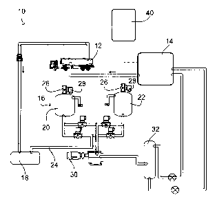
This vapor control logic system is for optimizing terminal loading capacity by controlling load rack fuel dispensing with a vapor recovery unit (VRU) to prevent undesirable shutdown of fuel dispensing at terminal facilities.


French Abstract

Le présent système logique de régulation des vapeurs est destiné à optimiser la capacité de chargement dun terminal en commandant la distribution de carburant à la rampe de chargement avec une unité de récupération de vapeur pour éviter un arrêt non souhaité de la distribution de carburant à des installations terminales.

Claims

Note: Claims are shown in the official language in which they were submitted.


7
CLAIMS
We claim:
1. A method for optimizing terminal loading capacity by controlling
the
operation of load rack fuel dispensing and the operation of a vapor recovery
unit (VRU) to
prevent undesirable shutdown of fuel dispensing at terminal facilities
comprising the steps
of:
providing a vapor recovery unit (VRU) comprising a first bed of adsorbent
and a second bed of adsorbent;
providing a vapor control logic system which controls the operation of the
VRU based upon one or more of the following operating parameters: VRU design,
and
ambient temperatures;
controlling the operations of the load rack fuel dispensing with the vapor
control logic system and adjusting a flow rate at the load rack based upon one
or more of
the following parameters: product temperatures, product type being loaded,
product type
previously loaded and rate of loading;
wherein the vapor control logic system uses a data processor to collect and
analyze the performance of the VRU and load rack fuel dispensing in real time;
and
wherein the data processor is in communication with a controller configured
to adjust the flow rate at the load rack based upon on the VRU parameters and
the load
rack parameters, in real-time.

8
2. The method according to claim 1 wherein a continuous emissions monitor
utilizes the data processor and the controller, to adjust the flow rate at the
load rack to
ensure that the VRU does not reach a shutdown situation.
3. The method according to claim 1 wherein the vapor control logic system is
configured to provide that the fuel flow rate can be reduced such that VRU can
perform at
an equivalent pace.
4. The method according to claim 1 wherein the data processor is configured to
prevent the VRU from shutting down by reducing the fuel flow rate to a level
that is equal
to or below the VRU capacity at a given time.

Description

Note: Descriptions are shown in the official language in which they were submitted.


1
OPTIMIZATION OF A VAPOR RECOVERY UNIT
FIELD OF THE INVENTION
The present invention relates to optimizing terminal loading capacity
by controlling load rack fuel dispensing to prevent undesirable shutdown of
fuel dispensing at terminal facilities.
BACKGROUND OF THE INVENTION
An oil depot (sometimes referred to as a tank farm) is an industrial
facility for the storage of oil and petrochemical products. Oil depots often
include terminals where the oil or petrochemical product is dispensed into
road tankers or other methods of transportation such as barges or pipelines.
Products dispensed from an oil terminal are generally in their final form and
are suitable for delivery to customers. The petrochemical products
dispensed at a terminal are often referred to as wholesale fuel.
Terminal technology has remained largely unchanged for many
years. The road tanker, or tanker truck, enters the terminal to obtain
wholesale fuel. The tanker truck is connected to the terminal to begin the
process of fueling. The vast majority of terminals use a bottom fill system
wherein the fuel fill line attaches to the bottom of the tanker and fills the
tanker from the bottom. When the tanker truck is filling, fuel vapors are
produced which must be safely disposed of. These fuel vapors may be
cornbusted or recovered with both methods having advantages and
disadvantages. When a tanker truck is filling, a vapor vent line is connected
to the tanker which transports the fuel vapors from the tanker truck to either
a recovery unit or a combuster.
Many terminals have begun using a vapor recovery unit (hereinafter
VRU) to recover the fuel vapors which are produced when filling a tanker
truck, or other fuel transportation vehicle. A typical VRU unit has at least
two adsorber vessels filled with adsorbent, such as activated carbon, a
vacuum pump or other source of vacuum, a return pump and a plurality of
valves. The adsorbers are properly piped and valved so that one adsorber
CA 2880942 2018-08-08

2
is currently receiving vapors while the other adsorber is in a regeneration
mode. When the loading process begins at the terminal, vapors are
transported to the active adsorber where they are adsorbed. Once an
adsorber vessel is nearly saturated or more commonly, cycles for a
predetermined cycle time, the vessel is switched to a regeneration mode
and the vapors are directed to the second adsorber vessel while the first
adsorber regenerates.
Regeneration occurs when the adsorbed fuel vapor is removed from
the activated carbon so that the carbon in the adsorber vessel is cleansed
and capable of adsorbing more fuel vapors. The fuel vapor is commonly
removed by vacuum and purge air stripping. A vacuum pump extracts the
fuel vapor from the saturated adsorbent and transfers it to an absorption
column. The absorption column vessel contains a packing material to
increase the efficiency of the absorption process. The fuel vapors from the
adsorber flow up through the absorption column, while liquid fuel flows down
through the packing. The liquid fuel absorbs the vapors retained in the
packing. The now liquefied fuel is pumped to the storage tank for reuse. All
fuel vapors not absorbed in the absorption column are returned by use of a
recycle line to the adsorber to be recovered.
The VRU is typically run in fifteen-minute cycles wherein one
adsorber is online and accepting fuel vapors while the other adsorber is
offline and in regeneration mode. Some terminals operate at full capacity
putting a larger load on the VRU. Such operations tend to strain the
efficiencies of the VRU's as the adsorbers commonly cannot regenerate as
quickly as they become saturated. Therefore, the terminal load rack
capacity exceeds the VRU capacity and the VRU may go into total
shutdown where both adsorbers regenerate at the same time and the load
rack operations are shutdown.
Therefore it is an object of this invention to maximize the terminal
loading capacity by controlling the load rack fuel dispensing with the VRU
performance outputs to prevent undesirable shutdown of the fuel dispensing
at terminal facilities.
CA 2880942 2018-08-08

3
SUMMARY OF THE INVENTION
The present invention monitors operating parameters for both the
operation of the load rack and the operation of the VRU and applies those
measurements to coordinate and maximize efficiencies during the loading
operation.
The factors which are evaluated to determine the VRU capacity include
but are not limited to the VRU design and equipment, the ambient temperature,
vapor pressure upon entering the VRU, and the amount of fuel vapor exiting the
VRU. The parameters being measured which pertain to the loading rack
operations include but are not limited to the product temperature, the product
type being loaded, the product that was previously loaded, and the rate of
loading. The present invention, in real time, provides these measurements for
both the VRU and the load rack to a controller which then provides real time
operating instructions to the VRU and load rack to assist in coordinating fuel
flow from the load rack with operating capacities of the VRU. This provides
for
maximized efficient fuel loading at the terminals.
The present invention optimizes the utilization of all data points to
determine VRU saturation levels, reduce the flow rate of fuel into the tanker
truck, thereby avoiding maximum saturation. Thus ensuring the VRU remains
in service and never becomes fully saturated, allowing more fuel to be
dispensed at the terminal throughout the given time period.
Accordingly, there is provided herein a method for optimizing terminal
loading capacity by controlling the operation of load rack fuel dispensing and
the operation of a vapor recovery unit (VRU) to prevent undesirable shutdown
of fuel dispensing at terminal facilities. The method comprises the steps of:
providing a vapor recovery unit (VRU) comprising a first bed of adsorbent
and a second bed of adsorbent;
providing a vapor control logic system which controls the operation of the
VRU based upon one or more of the following operating parameters: VRU
design, and ambient temperatures:
controlling the operations of the load rack fuel dispensing with the vapor
control logic system and adjusting a flow rate at the load rack based upon one
CA 2880942 2018-08-08

4
or more of the following parameters: product temperatures, product type being
loaded, product type previously loaded and rate of loading;
wherein the vapor control logic system uses a data processor to collect
and analyze the performance of the VRU and load rack fuel dispensing in real
time; and
wherein the data processor is in communication with a controller
configured to adjust the flow rate at the load rack based upon on the VRU
parameters and the load rack parameters, in real-time.
Other objects and advantages of the present invention will become
apparent to those skilled in the art upon a review of the following detailed
description of the preferred embodiments and the accompanying drawings.
IN THE DRAWINGS
Fig. 1 is a top plan view of a vapor recovery unit of the present
invention.
Fig. 2 shows a vapor control logic system.
DETAILED DESCRIPTION OF THE INVENTION
Referring now to Fig. 1 a tanker truck 12 enters a terminal 10 and
fuel is dispensed into tanker truck 12 from a storage tank 14. Fuel vapors are
recovered from tanker truck 12 and transported to a vapor recovery unit (VRU)
16. The fuel vapors may travel through condensation collection unit 18 prior
to
arriving at VRU 16. The condensation collection unit 18. however, is not
integral to the present invention. A typical VRU 16 has two adsorbers vessels
20 and 22 which are identical and preferably contain activated carbon to
capture the fuel vapors. In the preferred mode of operation, one adsorber
vessel 20 is on-line while the second adsorber vessel 22 is regeneration mode.
The second adsorber 22, during regeneration mode, is closed off from fuel
vapor line 24 and all fuel vapors flow to the on-line adsorber 20. For the
CA 2880942 2018-08-08

5
purposes of this illustration adsorber 20 will be on-line while adsorber 22 is
in
regeneration. The fuel vapors flow into adsorber 20 from loading tanker truck
12. When adsorber 20 is in fueling mode, the top 26 of the adsorber is vented
to the atmosphere. A continuous emissions monitor 28 (CEM) is attached to
monitor and analyze the effluent stream exiting the adsorber.
The present invention utilizes real-time data points collected from the
operations of the load rack and the operations of the VRU to optimize the
operations of the VRU 16 and prevent a fueling shutdown. Such data includes
but is not limited to: real-time ambient temperature, product temperature,
load
rate, product being loaded, product previously loaded, and the effluent rates
from the adsorbers.
Fig. 2 shows vapor control logic system 40. Logic system 40 includes
data processor 42 and controller 44. Vapor control logic system 40 uses data
processor 42 to collect and analyze the performance of VRU 16 and fuel
dispensing from the load rack in real-time. Data processor 42 is coupled to
controller 44 which is configured to adjust the flow rate at the load rack
based
on the parameters, data points and desired factors in real-time. Continuous
emissions monitor 28 utilizes data processor 42 and controller 44, to adjust
the
flow rate at the load rack to ensure that VRU 16 does not reach a shutdown
situation.
The present invention uses a data processor to collect and analyze the
performance of the VRU and load rack operations in real-time. The invention
provides that the fuel flow rate can be reduced such that VRU can perform at
an equivalent pace. In the preferred embodiment the data processor will
prevent the VRU from shutting down by reducing the fuel flow rate to a level
that is equal to or below the VRU capacity at any given time. The optimal fuel
flow rate will be determined utilizing the real-time data points such as
ambient
temperature, product temperature, product being loaded, product previously
loaded and the emissions from the VRU.
The above detailed description of the present invention is given for
explanatory purposes. It will be apparent to those skilled in the art that
numerous changes and modifications can be made without departing from the
CA 2880942 2018-08-08

6
scope of the invention, Accordingly, the whole of the foregoing description is
to be construed in an illustrative and not a limitative sense, the scope of
the
invention being defined solely by the appended claims.
CA 2880942 2018-08-08

Representative Drawing
A single figure which represents the drawing illustrating the invention.
Administrative Status

2024-08-01:As part of the Next Generation Patents (NGP) transition, the Canadian Patents Database (CPD) now contains a more detailed Event History, which replicates the Event Log of our new back-office solution.

Please note that "Inactive:" events refers to events no longer in use in our new back-office solution.

For a clearer understanding of the status of the application/patent presented on this page, the site Disclaimer , as well as the definitions for Patent , Event History , Maintenance Fee  and Payment History  should be consulted.

Event History

Description Date
Inactive: Late MF processed 2021-04-09
Maintenance Fee Payment Determined Compliant 2021-04-09
Letter Sent 2021-02-05
Revocation of Agent Requirements Determined Compliant 2020-06-22
Appointment of Agent Requirements Determined Compliant 2020-06-22
Appointment of Agent Request 2020-04-30
Revocation of Agent Request 2020-04-30
Common Representative Appointed 2019-10-30
Grant by Issuance 2019-04-09
Inactive: Cover page published 2019-04-08
Pre-grant 2019-02-19
Inactive: Final fee received 2019-02-19
Notice of Allowance is Issued 2019-02-08
Letter Sent 2019-02-08
Notice of Allowance is Issued 2019-02-08
Inactive: Approved for allowance (AFA) 2019-02-04
Inactive: Q2 passed 2019-02-04
Amendment Received - Voluntary Amendment 2018-08-08
Inactive: S.30(2) Rules - Examiner requisition 2018-02-08
Inactive: Report - QC passed 2018-02-05
Change of Address or Method of Correspondence Request Received 2018-01-10
Amendment Received - Voluntary Amendment 2017-04-28
Letter Sent 2017-03-16
All Requirements for Examination Determined Compliant 2017-03-09
Request for Examination Requirements Determined Compliant 2017-03-09
Request for Examination Received 2017-03-09
Inactive: Cover page published 2015-08-19
Application Published (Open to Public Inspection) 2015-08-13
Inactive: IPC assigned 2015-02-26
Inactive: First IPC assigned 2015-02-26
Inactive: IPC assigned 2015-02-26
Inactive: Filing certificate - No RFE (bilingual) 2015-02-10
Filing Requirements Determined Compliant 2015-02-10
Application Received - Regular National 2015-02-09
Inactive: QC images - Scanning 2015-02-05
Inactive: Pre-classification 2015-02-05

Abandonment History

There is no abandonment history.

Maintenance Fee

The last payment was received on 2018-11-01

Note : If the full payment has not been received on or before the date indicated, a further fee may be required which may be one of the following

  • the reinstatement fee;
  • the late payment fee; or
  • additional fee to reverse deemed expiry.

Patent fees are adjusted on the 1st of January every year. The amounts above are the current amounts if received by December 31 of the current year.
Please refer to the CIPO Patent Fees web page to see all current fee amounts.

Fee History

Fee Type Anniversary Year Due Date Paid Date
Application fee - standard 2015-02-05
MF (application, 2nd anniv.) - standard 02 2017-02-06 2016-12-01
Request for examination - standard 2017-03-09
MF (application, 3rd anniv.) - standard 03 2018-02-05 2018-02-02
MF (application, 4th anniv.) - standard 04 2019-02-05 2018-11-01
Final fee - standard 2019-02-19
MF (patent, 5th anniv.) - standard 2020-02-05 2020-01-31
Late fee (ss. 46(2) of the Act) 2021-04-09 2021-04-09
MF (patent, 6th anniv.) - standard 2021-02-05 2021-04-09
MF (patent, 7th anniv.) - standard 2022-02-07 2022-01-28
MF (patent, 8th anniv.) - standard 2023-02-06 2023-01-27
MF (patent, 9th anniv.) - standard 2024-02-05 2024-01-26
Owners on Record

Note: Records showing the ownership history in alphabetical order.

Current Owners on Record
MARATHON PETROLEUM COMPANY LP
Past Owners on Record
ANDREW U. KUMMERER
DALE, SR. BOYKIN
KEVIN STOODT
Past Owners that do not appear in the "Owners on Record" listing will appear in other documentation within the application.
Documents

To view selected files, please enter reCAPTCHA code :


To view images, click a link in the Document Description column. To download the documents, select one or more checkboxes in the first column and then click the "Download Selected in PDF format (Zip Archive)" or the "Download Selected as Single PDF" button.

List of published and non-published patent-specific documents on the CPD .

If you have any difficulty accessing content, you can call the Client Service Centre at 1-866-997-1936 or send them an e-mail at CIPO Client Service Centre.


Document
Description 
Date
(yyyy-mm-dd) 
Number of pages   Size of Image (KB) 
Description 2015-02-04 6 264
Abstract 2015-02-04 1 6
Drawings 2015-02-04 2 20
Claims 2015-02-04 2 68
Representative drawing 2015-07-15 1 8
Description 2018-08-07 6 244
Claims 2018-08-07 2 46
Representative drawing 2019-03-06 1 9
Maintenance fee payment 2024-01-25 46 1,890
Filing Certificate 2015-02-09 1 188
Reminder of maintenance fee due 2016-10-05 1 114
Acknowledgement of Request for Examination 2017-03-15 1 187
Commissioner's Notice - Application Found Allowable 2019-02-07 1 161
Commissioner's Notice - Maintenance Fee for a Patent Not Paid 2021-03-25 1 536
Courtesy - Acknowledgement of Payment of Maintenance Fee and Late Fee (Patent) 2021-04-08 1 423
Amendment / response to report 2018-08-07 19 813
Request for examination 2017-03-08 2 58
Amendment / response to report 2017-04-27 2 41
Examiner Requisition 2018-02-07 3 216
Final fee 2019-02-18 2 48