Note: Descriptions are shown in the official language in which they were submitted.
CA 02880944 2015-02-05
OPEN HOLE EXPANDABLE JUNCTION
BACKGROUND OF THE INVENTION
Field of the Invention
Embodiments of the invention generally relate to lining an open hole section
or sections of a wellbore. More specifically, embodiments of the invention
relate to
apparatus and methods for lining an open hole section or sections of a
wellbore to
form a junction where a lateral wellbore may be formed.
Description of the Related Art
Lateral wellbores are routinely used to more effectively and efficiently
access
hydrocarbon-bearing formations. Typically, the lateral wellbores are formed
from a
window that is formed in the casing of a central or primary wellbore,
typically
referred to as a junction. However, in some drilling applications, the casing
may not
extend completely along the primary wellbore due to costs, complexity, among
other
factors, and production is facilitated by an open hole wellbore that is not
completely
cased.
When forming a lateral wellbore in an open hole environment, it is difficult
to
maintain stability due to erosion at the junction. This instability
compromises depth
control for selective intervention, isolation and production. For example, it
is difficult
to maintain zonal isolation between formations and/or multiple lateral
wellbores
without having a known inside diameter where a seal may be positioned.
There is a need therefore, for an improvement in the integrity of the wellbore
that facilitates lateral wellbore formation and a known sealing surface
without using
expensive and complex cased hole design techniques.
SUMMARY OF THE INVENTION
Embodiments of the invention provides methods for lining an open hole
section or sections of a wellbore. In one embodiment, a method for lining an
open
1
CA 02880944 2015-02-05
hole section of a wellbore includes lowering a tubular member through a cased
section of the wellbore, expanding the tubular member in an open hole section
of
the wellbore, thereby anchoring the tubular member in the wellbore, forming a
window in a sidewall of the tubular member, and drilling a lateral wellbore
through
the window.
In another embodiment, a method for lining an open hole section of a primary
wellbore includes drilling a primary wellbore to a first depth, casing a first
section of
the primary wellbore from the surface to a second depth that is less than the
first
depth, running-in a first tubular through the first section to a third depth
that is
greater than the first depth and less than the second depth, expanding the
first
tubular within the primary wellbore and anchoring the first tubular in the
primary
wellbore, forming a window in a sidewall of the first tubular, and drilling a
second
wellbore through the window.
In another embodiment, a method for lining an open hole section of a
wellbore includes running-in a first tubular member through a cased section of
a
primary wellbore, expanding the first tubular member in an open hole section
of the
primary wellbore thereby anchoring the tubular member to the primary wellbore,
wherein an uncased section of the primary wellbore is disposed between the
cased
section and the first tubular member, anchoring the first tubular member in
the
primary wellbore, forming a window in a sidewall of the first tubular member,
and
drilling a first lateral wellbore through the window, wherein the first
tubular member
comprises at least one anchor section and a window section.
DETAILED DESCRIPTION OF THE DRAWINGS
So that the manner in which the above recited features, advantages and
objects of embodiments of the invention are attained and can be understood in
detail, a more particular description of the invention, briefly summarized
above, may
be had by reference to the embodiments thereof which are illustrated in the
appended drawings.
2
CA 02880944 2015-02-05
It is to be noted, however, that the appended drawings illustrate only typical
embodiments of this invention and are therefore not to be considered limiting
of its
scope, for the invention may admit to other equally effective embodiments.
Figures 1A-5 are section views representing one embodiment of a method
for cladding an open hole section of a primary wellbore to form a junction for
a
lateral wellbore.
Figures 6A-6E show various embodiments of anchor structures that may be
used with the cladding as described herein.
Figure 7 is a side cross-sectional view of another embodiment of a cladding
that may be used in place of the cladding shown in Figures 2-5.
Figure 8 is a side cross-sectional view of another embodiment of a cladding
expanded in a wellbore.
Figure 9 is a top cross-sectional view of another embodiment of a cladding
expanded in a wellbore.
Figure 10 is a cross-sectional view of an open hole production system
according to embodiments described herein.
DESCRIPTION OF EMBODIMENT OF THE INVENTION
Embodiments of the invention generally relate to lining an open hole section
or sections of a wellbore. Embodiments of the invention also relate to
apparatus
and methods for lining an open hole section or sections of a wellbore to form
a
junction where a lateral wellbore may be formed. Embodiments of the invention
also
relate to improving isolation between the primary wellbore and lateral
wellbores, as
well as between multiple lateral wellbores and/or between formations. While
the
invention is exemplarily described for use in wells for hydrocarbon
production, the
invention may also be utilized with other wells, such as geothermal wells.
Figures 1A-5 are section views representing one embodiment of a method
3
CA 02880944 2015-02-05
100 for cladding an open hole section 105 of a primary wellbore 110 to form a
junction for a lateral wellbore. The primary wellbore 110 may be coupled to a
wellhead 112 at the surface. The open hole section 105 and the primary
wellbore
110 may be a parent wellbore where one or more laterals maybe formed therefrom
to access hydrocarbons within a reservoir 115. The primary wellbore 110 may
also
include a cased section 120 that extends from the surface and ends at the open
hole section 105. The cased section 120 may include a casing 125, and cement
130 may be provided between a wall of the primary wellbore 110 and the casing
125. The open hole section 105 comprises an inner diameter that is defined by
a
wall 135 of the primary wellbore 110. In one embodiment, the open hole section
105 and an inner diameter 140 of the casing 125 defines a monobore, wherein
the
inner diameter of the open hole section 105 and the inner diameter 140 of the
casing 125 are substantially equal. The casing 125 may be 13 5/8 inch casing,
9
5/8 inch casing, 8 1/2 inch casing, or 7 inch casing, and the inner diameter
of the
open hole section 105 may be substantially equal to the inner diameter 140 of
the
casing 125.
Figure 1 B shows a portion of the open hole section 105 of Figure 1 where the
wall 135 of the primary wellbore 110 is under-reamed to form an under-reamed
section 145 in preparation for installation of a tubular cladding. The under-
reamed
section 145 may be formed in the primary wellbore 110 at a depth (or distance
from
the wellhead 112) where the wall 135 is unstable and/or in a region where the
formation is reactive with drilling fluids. Alternatively or additionally, the
under-
reamed section 145 may be formed at a depth (or distance from the wellhead
112)
where a lateral wellbore may be formed.
An inner diameter 150 of the open hole section 105 may comprise a first
diameter and the under-reamed section 145 may be formed to a second diameter
155 that is greater than the first diameter of the open hole section 105. In
one
example, the inner diameter 150 of the open hole section 105 is about 9 inches
(based on the inner diameter 140 of the casing 125) and the inner diameter of
the
under-reamed section 145 may be about 10 inches. A length L of the under-
4
CA 02880944 2015-02-05
reamed section 145 may be greater than a length (i.e., an expanded length) of
a to-
be-installed tubular cladding in the open hole section 105. The length L may
be
longer than the to-be-installed tubular cladding to ensure sufficient space
for tools
and/or operations that may be used in the primary wellbore 110 after the
tubular
cladding is installed.
Figure 2 shows a portion of the open hole section 105 wherein a cladding
200 has been installed in the under-reamed section 145 of Figure 1B. As
illustrated, the cladding 200 may be installed at a location within the open
hole
section 105 such that there is an uncased or open hole wellbore section
disposed
between the lower end of the casing 125 and the upper end of the cladding 200.
The cladding 200 may be one or more sections of an expandable (tubular) member
205 that is anchored to the wall 135 of the primary wellbore 110. The cladding
200
may be positioned in the primary wellbore 110 at a depth (or distance from the
wellhead 112) where the wall 135 is unstable and/or in a region where the
formation
is reactive with drilling fluids. Alternatively or additionally, the cladding
200 may be
positioned at a depth (or distance from the wellhead 112) where a lateral
wellbore
may be formed. The cladding 200 may be lowered into the primary wellbore 110
and expanded using conventional bottom-up or top-down expansion methods, such
as a swage/cone system, a jacking system, hydraulic expansion, and the like.
The
inner diameter 210 of the cladding 200 may be expanded to a diameter that is
substantially equal to the inner diameter 140 of the casing 125 and/or the
inner
diameter of the wall 135 of the primary wellbore 110.
The cladding 200 may include terminal ends, such as an uphole end 215A
and a downhole end 215B. One or both of the uphole end 215A and the downhole
end 215B may include an anchor structure 220. Alternatively or additionally,
one or
both of the uphole end 215A and the downhole end 215B may include a seal 225.
Examples of an anchor structure 220 are shown in Figures 6A-6E. Seals 225 may
be an elastomeric material that may be used alone or in conjunction with the
anchor
structures 220.
5
CA 02880944 2015-02-05
The cladding 200 may also include a marker 230 disposed on one or both of
the uphole end 215A and the downhole end 215B thereof. In the embodiment
shown, the marker 230 is disposed on the uphole end 215A of the cladding 200.
As
the location of the downhole end 215B may be known during run-in of the
cladding
200, the precise location of the uphole end 215A may not be known due to
linear
contraction of the cladding 200 during expanding of the cladding 200. Thus,
the
marker 230, which may be a radio frequency identification device, a magnetic
device or a radioactive marker such as a pip tag, provides location
information of
the uphole end 215A which may be used to determine the location of a window
for a
subsequent lateral wellbore formation process.
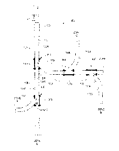
Figure 3 shows the setting of a packer 300 and a whipstock 305 in the
cladding 200. The packer 300 and whipstock 305 may be set by utilizing a
tubular
or wire/slick line-type string as is known in the art for the formation of a
window in
the area 310 of the cladding 200. The whipstock 305 includes a solid face 320
that
is angled in order to deflect the drilling assembly used to drill a to-be-
formed lateral.
The packer 300 and whipstock 305 may both include a through-bore 315 to allow
for production in zones below the packer 300 when the solid face 320 is
drilled out
(after formation of the lateral). The whipstock 305 is used to facilitate
formation of
the window by a milling process in the area 310. The whipstock 305 may be
oriented within the cladding 200 such that the solid face 320 is positioned to
direct
the drilling assembly toward the area 310, The area 310 may be perforated to
assist
in formation of the window. When the area 310 is perforated, the cladding 200
may
be oriented within the primary wellbore 110 prior to expansion of the cladding
200.
Figure 4 shows an open hole junction 400 by the formation of a lateral
wellbore 405. A window 410 may be formed through the cladding 200 using a mill
to form the lateral wellbore 405. Figure 5 shows the further drilling of the
lateral
wellbore 405 that is angled relative to the primary wellbore 110.
Figures 6A-6E show various embodiments of anchor structures 220 that may
be used with the cladding 200 as described herein. Figures 6A-6D are side
cross-
6
CA 02880944 2015-02-05
sectional views of the cladding 200 and the anchor structure 220, and Figure
6E is a
cross-sectional plan view of the cladding 200 showing another embodiment of an
anchor structure 220.
Figure 6A shows an anchor structure 220 comprising a plurality of abrasive
particles 600 disposed on an outer surface of the cladding 200. Figure 6B
shows
an anchor structure 220 comprising a plurality of grip members 605. Each of
the
grip members 605 include an elastomeric portion 610 and an abrasive portion
disposed thereon, such as a plurality of abrasive particles 600. The
elastomeric
portion 610 utilized with the grip members 605 may also provide a sealing
aspect to
the grip members 605. The abrasive particles 600 may include materials that
are
harder than the material of the cladding 200, such as a carbide material.
Figures
6C and 6D show other embodiments of an anchor structure 220 that may include a
carbide inserts 615 having one or more gripping members 617. The one or more
gripping members 617 may be teeth utilized for gripping the cladding 200
and/or the
surrounding formation, and preventing lateral movement of the cladding 200
within
the wellbore. Figure 6E shows another embodiment of an anchor structure 220
comprising one or more longitudinally oriented strips 620 disposed on the
outer
surface of the cladding 200. It is noted that any a combination of the anchor
structures 220 shown in Figures 6A-6E may be combined for use with the
cladding
200. Additionally, seals may be used in combination with any of the anchor
structures 220.
Figure 7 is a side cross-sectional view of another embodiment of a cladding
700 that may be used in place of the cladding 200 shown in Figures 2-5 to form
the
open hole junction 400. The cladding 700 includes multiple tubular sections
shown
as anchor sections 705A and 705B having a window section 705C therebetween,
Each of the sections 705A-705C may be expandable members that are run-in and
set in the primary wellbore 110 using conventional expandable methods. Each of
the sections 705A-705C may include various coupling mechanisms, such as a pin
and box coupler 710 or a pin-pin coupling 715. A lateral wellbore may be
formed in
area 720 of the window section 7050 by the process described in Figures 3-5.
The
7
CA 02880944 2015-02-05
anchor sections 705A and 705B are used to stabilize the window section 7050.
At
least the anchor sections 705A and 705B include contact structures 725 that
may
be one or a combination of anchor structures 220 and seals 225 as described
herein. Depending on the modulus of elasticity of the formation, contact
structures
725 may also be used on the window section 7050.
In one embodiment, the window section 7050 comprises an expanded length
of about 30 feet, or greater, and the anchor sections 705A, 705B comprise an
expanded length of about 10 feet, or greater. The lengths of the sections 705A-
7050 provide enough space to mill a window having a length of about 20 feet in
order to form a lateral wellbore.
Figure 8 is a side cross-sectional view of another embodiment of a cladding
800 expanded in a wellbore 805. The cladding 800 may be one or more joints of
an
expandable tubular. However, a wall 810 of the wellbore 805 is under reamed to
a
first diameter 815A that receives a portion of the cladding 800, and a second
diameter 815B is formed below the first diameter 815A. The second diameter
815B
may be used to accommodate a centering anchor 820. A window may be formed in
an area 825 by milling the cladding 800 to form an open hole junction. While
the
centering anchor 820 is shown below the area 825, an additional centering
anchor
(and second diameter) may be formed above the area 825. The second diameter
815B may be greater than the first diameter 815A. As an example, the first
diameter 815A may be a 9 5/8 inch under-ream while the second diameter 815B
may be a 10 3/4 inch under-ream. In one embodiment, the expanded inner
diameter 830 of the cladding 800 is substantially equal to an inner diameter
835 of
the wellbore 805.
Figure 9 is a top cross-sectional view of another embodiment of a cladding
900 expanded in a wellbore 905. In this embodiment, the cladding 900 is
expanded
into a hex shape to enhance frictional contact between the cladding 900 and
the
wellbore 905. Anchor members and/or seals may be used on the cladding 900 to
further increase frictional contact. The cladding 900 may be used as the
cladding
8
CA 02880944 2015-02-05
200 described in Figures 2-5 or the cladding 700 described in Figure 7.
Figure 10 is a cross-sectional view of an open hole production system 1000.
The open hole production system 1000 includes a plurality of lateral wellbores
1003
branching from a primary wellbore 110. The lateral wellbores 1003 are formed
through windows 1008 provided by a process described in Figures 3 and 4. The
open hole production system 1000 also includes the primary wellbore 110 and a
plurality of open hole sections 105 between sections of cladding 1005. The
cladding 1005 may be the cladding 200 described in Figures 2-5, the cladding
700
described in Figure 7, the cladding 800 described in Figure 8, or the cladding
900
described in Figure 9. Each of the regions comprising the cladding 1005
comprise
an open hole junction 400.
Use of packers 300 and/or whipstocks 305 having through-bores in each
open hole junction 400 allows production from various zones of the formation.
Once a lateral wellbore 1003 is drilled, the cladding 1005 may be run through
the
window 1008. The cladding 1005 may be anchored in the open hole sections 105
beyond the window 1008 (within the lateral wellbore 1003), or somewhere above
the window 1008 (such as in the open hole section 105). In one embodiment, the
whipstock 305 may be retrieved to allow access to open hole sections 105 below
or
beyond the whipstock 305 (e.g., any one or combination of zones A-E). In
another
embodiment, if it is desired to regain access to the open hole sections 105
below or
beyond the whipstock 305 (or provide fluid flow from any one or combination of
zones A-E) a window may be milled through the whipstock 305 to provide access
to
the desired open hole section 105 below or beyond the whipstock 305, In
another
embodiment, if it is desired to regain access to the open hole sections 105
below or
beyond the whipstock 305 (or provide fluid flow from any one or combination of
zones A-E), a window may not be milled. Instead, perforations are shot and
penetrate through the face of the whipstock 305, so allowing fluid to flow
therethroug h.
Seals 1010 may be positioned against the inner diameter of the cladding
9
CA 02880944 2015-02-05
1005 to provide selective production from zone A while zones B-E are isolated.
The
seals 1010 may be removed (e.g., by drilling) and placed in other positions
within
the cladding 1005 to produce from desired zones while isolating other zones.
The
monobore aspect of the open-hole/cladding (substantially the same diameters
between the open hole sections 105 and the cladding 800) provides for the
utilization of standard tools and equipment. The use of standard tools and
equipment lowers production costs.
While the foregoing is directed to embodiments of the invention, other and
further embodiments of the invention may be devised without departing from the
basic scope thereof, and the scope thereof is determined by the claims that
follow.