Note: Descriptions are shown in the official language in which they were submitted.
1
Vessel comprising a mooring connector with a heave compensator
Field of the invention
The invention relates to a vessel having a hull, a contact area for attaching
to a
structure, a lifting device on the vessel and a lifting cable attached to the
lifting device
and extending along a heave compensating member on the vessel and along a
substantially vertical lifting trajectory to a connect position below keel
level for
attaching to the structure, a compensator arm with a pivot end pivotally
connected to a
pivot point on the vessel at a predetermined transverse distance from the
lifting
trajectory, a cable guide element being attached to a free end of the
compensator arm at
or near the lifting trajectory, guiding the lifting cable in the direction of
the pivot point,
the arm being at or near the free end connected to the displacement device.
The
invention also relates to a mooring system comprising a submerged mooring
structure,
and a vessel having a heave compensating system and to a method of mooring
such a
vessel.
Background of the invention
Such a vessel is known from US patent application no. 2003/0005875. This
document
discloses a dynamically positioned vessel moored via a cavity in its hull to a
releasable
submerged mooring buoy. A hoisting device, comprising an A-frame lowers from
the
side of the vessel a light-weight pulling line that can be attached to the
submerged
buoy. At the end of the pulling line a connection unit is attached that can be
coupled to
the buoy, as well as a hawser extending through the moompool of a turret to a
winching device at the top of the turret, on deck of the vessel. When the buoy
is
coupled to the connection device, the pulling line is released and the buoy is
raised by
use of the hawser and the winching device to connect to a cavity at the lower
end of the
turret. The A frame of the hoisting device can be manoeuvred via a hydraulic
cylinder
for proper positioning and the winch carrying the pulling line is heave-
compensated.
During connection, the winching device may be subject to large forces induces
by the
heave motion of the vessel and the buoy. The lifting capacity of the known
winch at the
top of the turret needs to be large, for instance 1000 tons or more, in order
to lift the
buoy to its locking position in the cavity, and will require significant deck
space.
From US patent no. 7,614,927 a floating production storage and offloading
(FPSO)
vessel is known, having in its hull a cavity in which a riser supporting buoy
is
connected to a cylindrical shaft in the vessel. The buoy has positive buoyancy
that, in
CA 2881044 2019-09-13
CA 02881044 2015-02-04
WO 2014/023664 PCT/EP2013/066310
2
the disconnected state of the buoy, keeps it afloat at a depth below the wave
active zone
and is connected to a lifting cable that is attached to a winch on the vessel.
The lifting
cable runs along a pulley and reversing pulley of a hydraulic heave
compensator
comprising a horizontally placed cylinder situated on deck beside the
moonpool. The
heave compensator keeps the lifting rope tight, preventing it from going slack
when the
vessel moves up and down on the waves. The riser supporting buoy is lifted
upwards
via the winch until it locks into position in the moonpool via guiding and
locking arms,
while the vessel is kept in position by a dynamic positioning system. The
known heave
compensator takes up a relatively large deck space. During connecting of the
buoy to
the locking arms, the known heave compensating system will be deactivated to
prevent
relative motion of the buoy and the vessel, which may result in large forces
acting on
the pick up cable and on the winch.
From US patent no. 7,513,208 a disconnectable mooring system for offshore
structures
such as FSO's, FPSO's, LNG regas import terminals or LNG transport vessels is
known comprising disconnectable mooring buoy that is provided with a retrieval
system and an intermediate buoy support equipment for detachably connecting
the
buoy to the bottom of a turret assembly that is rotatably positioned in the
hull. A pull-in
line extends from the buoy to a winch on the vessel, via a hollow bore
hydraulic
cylinder that comprises a rotatable hydraulic chain jack. The lifting cable
near the buoy
is formed by a chain section, which engages, when the buoy is pulled upward
against
the hull, with the hydraulic chain jack. The hydraulic cylinder assembly
supports the
load of the buoy while the turret assembly is rotated such that the piping on
the turret is
brought into proper alignment with the risers on the buoy. After alignment,
the
hydraulic cylinder raises the buoy at least 1 m into a position adjacent to
the keel of the
vessel where it is locked, after which the buoy is dewatered, the turret-buoy
piping is
connected and ropes and chains are stored for future buoy disconnection. The
known
system may during connection of the buoy be subject to large forces acting on
the pull-
in line caused by heave movements of the vessel.
It is an object of the present invention to provide a vessel having a lifting
system, in
particular a mooring system, in which a submerged structure can be rapidly
connected
to the vessel while forces exerted on the lifting cable caused by heave
movements are
reduced. It is in particular an object to provide a lifting system allowing a
transition
from motion compensated lifting to a lifting mode exerting a large force in
the last part
CA 02881044 2015-02-04
WO 2014/023664 PCT/EP2013/066310
3
of the lifting trajectory, for instance when the object is raised near to or
above water
level, or for providing a preload of the structure against the vessel. It is a
further object
to provide a vessel having a heave compensator of improved design that takes
up
relatively little deck space and that allows rapid and controlled connection.
It is another
object of the invention to provide a heave compensator which reduces cable
movements during heave compensation and which has an improved efficiency.
Summary of the invention
Hereto the vessel according to the invention is characterized in that the
lifting trajectory
extends through the contact area, the lifting device and the cable being
adapted for
lifting of the structure to the contact area, the displacement device being
arranged
substantially in line with the lifting trajectory and being adapted for
pivoting the arm up
and down during operation of the lifting device for heave compsensation and
for raising
the arm at a stationary lifting device.
The pivot arm provides a heave compensator by moving upwards or downwards
while
the structure is pulled towards the vessel via the cable by the lifting
device, the lifting
cable running along the cable guide element. In the heave compensating member
according to the invention, no losses occur by the lifting cable passing over
the rope
sheaves during heave compensation, which results in a more efficient and
improved
heave compensation performance. Also, less cycles are made by the rope (which
can
for instance be synthetic or steel wire) during heave compensation, resulting
in an
improved life time of the lifting cable. The pivoting arm provides a compact
heave
compensator and does not require a large transverse stroke of the displacement
device,
hence saving space on the vessel. The small transverse dimensions of the arm
allow it
to be mounted inside the turret column of the vessel, saving space in the
upper turret.
The displacement device according to the invention is attached to the arm near
the free
end thereof, substantially in line the vertical lifting trajectory, so that no
moments are
transferred by the displacement device to the vessel during lifting. The
compensator
arm and guide element can be so dimensioned that during raising and lowering
of the
compensator arm, the rope is stationary relative to the guide member. This
results in
reduced heat generation in the lifting wire during heave compensation in
syntentic
lifting cables, which heat generation is due to multiple bending at the same
location of
a synthetic rope. Furthermore, the specific design of the arm resulting in a
stationary
lifting cable during heave compensation allows in the connecting stage of the
buoy,
CA 02881044 2015-02-04
WO 2014/023664 PCT/EP2013/066310
4
when the upper part of the buoy is situated near the fee end of the heave
compensator
arm, to use the arm for pulling the buoy upwards into its final locking
position.
The lifting device according to the invention can be used to lift heavy subsea
structures
from below water level to the vessel, such as diving bells, blow-out
preventors
(BOP's), templates, manifolds, pumps or other subsea well equipment. In a
preferred
embodiment, the structure is formed by a mooring structure, the contact area
being
arranged at the hull near keel level or externally of the hull for attaching
the vessel to
the mooring structure. The contact area can be formed by a fixed part on the
vessel or
can be situated on a turret around which the vessel can weathervane. The
mooring
structure can be a submereged riser supporting buoy, carrying risers that are
attached to
a subsea hydrocarbon well and anchored to the sea bed via anchor lines
including
chains, steel or synthetic cables or combinations thereof.
During the first stage of lifting of the mooring structure, the heave
compensating force
exerted by the displacement device can be relatively low, as the mooring
structure is
submerged and located at a depth below the wave active zone. When the mooring
structure approaches the vessel, the lifting device can be stopped and the
mooring
structure can be pulled to its final connecting position by pivoting the
compensator arm
to its upward limit by contraction of the displacement device. As the mooring
structure
in the connecting phase supports relatively long lengths of anchor lines and
risers, and
can be situated at least partly above water level, the loads will be
relatively high, which
high loads can be effectively taken up by the compensator arm and the
displacement
device. By means of the high forces exerted by the compensator arm, a large
preload of
the mooring structrure against the hull can be applied.
Preferably the lifting capacity of the displacement device is at least 100
ton, preferably
at least 1000 ton. The same applies for the lifting cable.
In one embodiment, a second cable guide element is situated near the pivot end
of the
compensator arm, the lifting cable being guided from the first cable guide
element to
the second cable guide element.
The vessel according to the invention may comprise an off-shore structure such
as an
FPSO, FSO, FSRU, a barge or any other offshore structure which needs to be
moored
to the sea bed in a disconnectable manner via the mooring structure (e.g. a
disconnectable catenary anchor leg mooring ¨ CALM- system, for example for
arctic or
hurricane area's). The mooring structure according the invention may comprise
a
CA 02881044 2015-02-04
WO 2014/023664 PCT/EP2013/066310
mooring buoy, anchored to the sea bed. The mooring buoy may carry one or more
hydrocarbon product risers, connected to a subsea well. The connect position
on the
vessel may be formed externally on the hull near keel level or may comprise a
cavity in
the hull for receiving the mooring structure. The receiving cavity may be
comprised in
5 a turret around which the vessel can rotate, the mooring structure being
connected to
the turret in a fixed orientation. Alternatively, the mooring structure may
comprise a
central geostationary part connected to the sea bed and a rotating part
attached to the
central part via bearings, the rotating part being fixedly connected to the
hull in the
contact area. The lifting cable may comprise steel or synthetic wire rope, a
chain
section or combinations thereof. The lifting device according to the invention
may
comprise one or more winches, a hydraulic jacking system or combinations
thereof.
The displacement device may comprise one or more hydraulic or pneumatic
cylinders
or an electric displacement device or combinations thereof.
In a preferred embodiment of a vessel according to the invention, a connector
is
attached to the free end of the arm for engaging with a complementary
connector on the
mooring structure when it is pulled upward via the lifting cable. By providing
a
connector at or near the free end of the arm, the weight may be taken off the
lifting
cable in the final connecting stage by engaging the connector with the buoy.
The
mechanical connector allows the arm to exert a large lifting force on the
buoy,
exceeding the maximum load capacity of the lifting cable. The maximum pull-in
load
for a cable may for instance be a few hundreds of tons, whereas the lifting
capacity of
the arm and connector may be over a thousand tons. During transfer of the
weight of
the buoy from the lifting cable to the arm, the heave compensation is still
active, the
arm and the connector being moved upward or downward by the displacement
device.
The guide means and compensator arm are dimensioned in such a way that the
cable
does not move along the guide means on the free end when the arm moves up or
down
for heave compensation, so that no relative movement between the connectors on
the
buoy and on the arm occurs during heave compensation. The connector allows
controlled mechanical connection of the buoy to the heave compensating system
without impact or relative movements.
In a further embodiment of a vessel according to the invention, the
displacement device
is provided with a displacement control unit operating the displacement device
in a
heave compensating mode while the buoy is lifted via the lifting cable
allowing upward
CA 02881044 2015-02-04
WO 2014/023664 PCT/EP2013/066310
6
and downward displacement of the pivot arm at relatively low forces and after
providing a fixed attachment of the buoy to the arm, operating the
displacement device
in a connector mode while the lifting device is stationary, moving the
displacement
device in an upward direction at a relatively large force to move the buoy to
a locking
position. This "ratcheted" mode of the heave compensating member results in
gradual
upwards displacement of the buoy in the final coupling stage utilizing the
upwards
heave movements of the buoy in a controlled manner.
The displacement device may comprise one or more hydraulic cylinders, the rod
side of
which is connected to the free end of the compensator arm, which cylinders may
have a
stroke of for instance 4 typically 5 m. The cylinders are controlled by
selectively
supplying compressed air to the rod side, to have an average position which is
situated
about the mid-point of the cylinders. When the buoy is lifted, its weight
depending
from the cylinders increases, so the control unit commands a pressure increase
on the
cylinders to compensate for the weight increase, for instance by successively
connecting compressed gas reservoirs with increasing pressure to the
cylinders. In the
locking stage, the control unit may command a check valve attached to the rod
side of
the cylinders to allow one way flow of compressed air into the rod side of the
cylinders,
until they are completely retracted and the buoy is raised in its uppermost
position, in
which it is connected. The buoy may be connected in a receiving cavity near
the hull,
for receiving the mooring structure, via a locking device for locking the
mooring
structure into the cavity. The passive heave compensating system according to
the
invention, using accumulators to provide a spring force, can be operated at
reduced
power.
In an embodiment, a connector may be attached at or near the end of the
compensator
arm and may comprise locking jaws for fitting around a clamping rod on a
mooring
structure, the lifting cable passing through the locking jaw to the first
guide means.
Alternatively, a connector comprising a chain stopper may be attached to the
hull, the
lifting cable near the mooring structure being comprised of a chain section
for engaging
with the chain stopper. During the connecting stage, the chain section of
lifting cable is
pulled along the chain stopper by the upward movement of the compensator arm,
which
allows only upward movement, so that the mooring structure is stepwise lifted
to its
connect position.
Brief description of the drawings
CA 02881044 2015-02-04
WO 2014/023664 PCT/EP2013/066310
7
A number of embodiments of a mooring system according to the invention will by
way
of non-limiting example be explained in detail with reference to the
accompanying
drawings.
In the drawings:
.. Fig. 1 schematically shows a mooring system according to the present
invention,
Fig. 2 shows the mooring buoy and heave compensator arm of fig. 1 on an
enlarged
scale,
Fig. 3 shows a detailed view of the displacement device in the form of three
hydraulic
cylinders and a clamp connected near the fee end of the heave compensator arm,
Fig. 4 shows a perspective view of the heave compensating member according to
the
invention in a first lifting stage in which the buoy is situated at larger
water depths,
Fig. 5 shows the heave compensating member of fig. 5 with the mooring buoy
approaching the vessel and the connecting rod in an extended state,
Fig. 6 shows the heave compensator member of fig. 5, the clamping member being
engaged with the connecting rod,
Fig. 7 shows the heave compensator of fig. 6, in the final connect position in
which the
heave compensator arm is moved to its most upward position.
Fig. 8 shows a schematic hydraulic diagram of the heave compensating system
and its
control according to the invention,
Fig. 9 shows an alternative embodiment of locking the buoy to the heave
compensator
member via a chain locker, in the connecting phase,
Fig. 10 shows an embodiment wherein no connector is provided on the free end
of the
heave compensator member, and
Fig. 11 schematically shows an embodiment in which the contact area and the
heave
compensating member are situated outboard from the hull of the vessel.
Detailed description of the invention
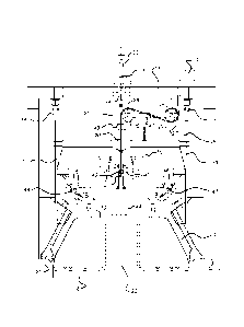
Fig. 1 shows a vessel 1, such as a FSO, a FPSO, a barge or any other vessel
that is to be
anchored to the sea bed 2. In the hull 3 of the vessel 1, a receiving cavity 4
defines a
contact area 5 for engaging with a mooring buoy 6. The contact area 5,that is
situated
near keel level 7, may also comprise a differently shaped section of the hull
3, for
instance a flat section for abutting against a planar connection surface of
the mooring
buoy 6, that may have a truncated conical shape, a cylindrical shape or any
other
suitably shaped contacting interface.
CA 02881044 2015-02-04
WO 2014/023664 PCT/EP2013/066310
8
The mooring buoy 6 is anchored to the sea bed 2 via mooring lines 10, that may
be
formed of catenary chains, synthetic wire ropes, steel cables or combinations
thereof.
Hydrocarbon product risers 11 extend from a subsea well to the mooring buoy 6
and
are to be connected to product piping and a product swivel on the vessel (not
shown).
The subsea well may be situated for instance 2-3 km below water level 17. The
mooring buoy 6 is connected to the vessel via a locking device 12, such as for
instance
hydraulic clamps, that engage with the buoy and fix its position within the
receiving
cavity 4. The mooring buoy 6 may be provided with a central geostationary part
and an
outer rotating part mounted on the central part via bearings, such that the
vessel 1, after
connecting to the buoy 6, can weathervane around the buoy in dependence on the
direction of wind and current. Alternatively, the vessel 1 is provided with a
cylindrical
turret 13, formed in a vertical shaft that extends through the hull of the
vessel, and
provided with axial bearings 14 and radial bearings 15. The turret 13 is
geostationaty,
while the hull 3 weathervanes around the turret. Via a torroidal swivel or a
pipe swivel
assembly, the product piping on the turret is connected to the product piping
on the
vessel, for allowing relative rotation.
When the vessel 1 is decoupled from the buoy 6, for instance when severe
weather
conditions require the vessel to be moved, the buoy 6 sinks to a neutral
buoyancy level
that is below the wave active zone, for instance at a depth of 100 m below
water level
17. For reconnecting the mooring buoy 6 to the vessel, it is attached to a
lifting cable 20
that is wound around a lifting device, such as a winch 21, on the vessel 1.
The lifting
cable 20 is guided along a vertical lifting trajectory via a heave
compensating member
23 that can pay out or take in the lifting cable 20 to vary its length in
dependence of
upward and downward heave movements of the vessel 1, in order to avoid
excessive
loads on the lifting cable 20. A control unit 24, comprising a computer (PLC),
controls
the response of the heave compensating member 23 and controls the stroke and
spring
stiffness of the heave compensating member at various distances of the mooring
buoy 6
from the vessel 1. Upon lifting of the buoy 6, the weight will increase
because of the
increasing length of the anchor lines 10 that are lifted from the sea bed and
of the risers
that arc supported by the buoy 6.
Fig. 2 shows the mooring buoy 6 and heave compensating member 23 on an
enlarged
scale in a connect position The heave compensating member 23 comprises a
compensator aim in the form of a swing frame 25 that is with a pivot end
hingingly
CA 02881044 2015-02-04
WO 2014/023664 PCT/EP2013/066310
9
connected to a wall 26 of the turret 13 in a pivot connection 27. A free end
28 of the
swing frame 25 carries a guide element in the form of a first sheave 30, and
at its pivot
end a second sheave 31, along which sheaves 30, 31 the lifting cable 20 is
guided from
the vertical lifting trajectory 35 to the winch 21. The free end 28 of the
swing frame 25
is connected to a displacement device in the form of a number, for instance
three,
hydraulic cylinders 36, 36', 36" that are with their upper ends 37 connected
to a
support frame 38 that is supported on a deck 39 of the turret 13.
The cylinders 36-36" of the heave compensating member 23 arc, in the
embodiment
shown in fig. 2, also attached to a clamp 40 which engages in the connect
position
shown, with a connecting rod 41 of the mooring buoy 6. The connecting rod 41
is
retractably placed in a conical housing 44 on a top surface 52 of the buoy 6.
The clamp
40 has a hollow core, along the center line of which runs the lifting cable 20
to be
attached to the rod 41 in a cable connecting point 42. The clamp 40 is
connected to the
swing frame 25 via a cardanic hinge 43, so that the buoy can swing in two
perpendicular directions as well as rotate around a vertical axis upon
connection. In its
lifting position, the clamp 40 is engaged with the connecting rod 41, and the
weight of
the buoy 6 is taken off the lifting cable 20. The last upward stroke of the
buoy 6 is
made by pivoting the swing frame 25 to its upward position and engaging the
clamps
47, 48 with the buoy 6 to fix it into the receiving cavity 4. A guiding cage
50 limits the
amplitude of the swinging motion of the buoy 6 hanging on the clamp 40, while
fenders
51, which may comprise metal-reinforced elastomeric pads, guide the buoy 6
into the
receiving cavity 4 at keel level 7.
The swing frame 25 is capable of pivoting upward and downwards around a
substantially horizontal equilibrium position, with a stroke of 2m in each
direction. The
geometry of the swing frame 25 and the two sheaves 30, 31 is designed in such
a way
that during lifting and lowering of the swing frame 25 by pivoting in the
pivot
connection 27, while the winch 21 is stationary, the lifting cable 20 is
stationary on the
lifting sheave 30. This is important for the pull-in phase of the buoy. The
locking of the
buoy can be executed without relative motion between the heave compensated
clamp
40 and the connecting rod 41.
Fig. 3 shows a frontal view of the heave compensating member 23 with the three
cylinders 36, 36', 36" connected to the support frame 38. The clamp 40 is
connected to
the free end 28 of the swing frame 25 via the cardanic hinge 43. The lifting
cable 20
CA 02881044 2015-02-04
WO 2014/023664 PCT/EP2013/066310
passes through the clamp 40 to the connection point 42. The connecting rod 41
is
retracted from the housing 44 that projects from the top surface 52 of the
buoy. A
spherical surface 53 on the end of the connecting rod 41 engages with a
complementary
surface on the housing 44 to provide a spherical bearing allowing a swinging
relative
5 movement of the connecting rod 41 and the clamp 40 on the one hand, and
the conical
housing 44 on the other hand.
Fig. 4 shows the buoy 6 at a depth of 100m below water level, the winch 21
lifting the
buoy at a speed of for instance 2m/min. The static load may be about 0 kN and
gradually increases to for instance 4000 kN when the buoy is raised. The
pressure
10 inside the cylinders 36-36¨ is relatively low (e.g. 8 bar) and the
compensator arm 25 is
maintained on average at a horizontal position with a heave compensation
stroke of
about 1.5 m in an upwards and in a downwards direction.
Fig. 5 shows that at a depth of the buoy 6 of for instance 100-80m, the rod 41
is
released from the housing 44. In Fig. 6 it can be seen that, while the
cylinders 36-36-
are in a heave compensating mode, the locking device of the clamp 40 is
engaged with
the rod 41 and the weight of the buoy 6 is taken off the lifting cable 20. The
control
unit 24 then switches the cylinders 36-36" into a ratchet mode, in which the
arm 25 can
only move upwards relative to the hull 3, by means of a non-return valve in
the
hydraulic circuit of the cylinders 36 (see also fig. 8). In this way, the buoy
6 can only
move upwards and wave action helps raising the buoy 6 to its locking position,
In case
no wave motion is present, the compensator arm 25 will be raised by the
cylinders 36-
36" to its locking position, that is shown in Fig. 7, in which position the
clamps 47,48
are engaged to lock the buoy 6 inside the receiving cavity 4. The lifting
capacity of the
cylinders 36- 36" in the final stage may be about 1500 ton.
Fig. 8 shows a schematic hydraulic diagram of the heave compensating member 23
according to the invention. The three cylinders 36,36' and 36" have for
instance
typically a stroke of about 5 m. The mid cylinder 36 has a mechanical cushion
55 at its
piston 56 for limiting the upward stroke. The hydraulic cylinders 36,36%36"
are loaded
only under tension, the load hanging from the cylinders so that the cylinder
rod
diameter can be relatively small to make the pulling capacity of these
cylinders highly
effective. The upper ends of the cylinders 36-36" are filled with a gas, such
as
nitrogen, and are connected to a small gas vessel 57, for prevention of
moisture
accumulating in the upper cylinder ends. The lower ends of the cylinders 36-
36"
11
comprise a hydraulic fluid such as oil and are connected via a valve 60 to the
outlet of a
piston type medium separator 58. An individual valve 60 may be provided for
each
respective cylinder 36.36',36". The medium separator 58 is connected to a
hydraulic
power unit 61 for filling or emptying the cylinders 36-36" and the medium
separator
58 via the valves 62,63 and for pressurizing the rod section of the cylinders
36-36" via
the valve 62 with a pressure of several hundreds of bars for a final lifting
stroke at the
connection stage of the buoy 6. The valves 62. 63 and hydraulic power unit 61
may be
controlled by the control unit 24.
The gas volume connected to the medium separator 58 is divided into a number
of
reservoirs 65, 66 each connected to a compressor 70 and each provided with a
respective controllable valve 67, 68, which valves 67,68 are connected to the
control
unit 24 via signal line 69 for selectively opening and closing of the valves.
The
reservoirs 65 arc storage vessels at a pressure of for several hundreds of
bars, the
reservoirs 65 being charged at stepwise increasing pressures of for instance a
few bar,
to several tens of bars.
The cylinders 36-36¨ and the medium separator 58 are connected to for the
control unit
24 for determining the cylinder stroke and separator mid position.
At larger depths of the mooring buoy 6, the static load on the cylinders 36-
36" is
relatively low and only the first of reservoirs 65 is connected to the upper
end of the
cylinders to result in a relatively low pressure of for instance 8 bar. The
cylinders 36-
36¨ are in balance and are able to absorb small impact loads required for the
first pull-
in phase. When the buoy 6 is lifted further, the static pressure at the rod
side of the
cylinders is increasing and the gas pressure generated by the reservoirs 65 is
increased
by successive opening of the valves 67 of those reservoirs 65 having
increasing
pressures. As the static load is more or less proportional with the lifting
height of the
buoy, opening of the valves 67 can be carried out by the control unit 24 in a
linear
manner. For any non-linearity in the load function, also the position of the
cylinders
measured by a sensor is used in a position feedback control loop in the
control unit 24.
When the buoy 6 is lifted, the average position of the cylinders 36-36"
changes, and
the cylinders rods will he extended due to compression of the gas spring below
the
piston under higher vertical loads. Every time the average pressure in
cylinders exceeds
a certain threshold limit, the next gas reservoir 65 at a higher pressure is
connected. In
CA 2881044 2019-09-13
CA 02881044 2015-02-04
WO 2014/023664 PCT/EP2013/066310
12
this embodiment, 5 reservoirs are used. Each reservoir is pre-charged at a
predetermined number of bars higher pressure than the preceding reservoir.
The control unit 24 senses this change in average position and opens one or
more of the
valves 67, as a result of which the cylinders 36-36" return to their mid
positions. The
cylinders 36-36" should move around their mid positions. When the hydraulic
pressure
in the rod section of the cylinders 36-36" is larger than a predetermined
threshold
value, the gas pressure in the cylinder top ends is gradually reduced to a few
bar.
The valve 60 is controlled by the control unit 24.When controlled to be in a
closed
position, the valve 60 acts as a check valve allowing only flow from the
medium
separator 58 towards the cylinders 36-36". This "ratchet" function is applied
during the
final pull-in phase of the buoy 6. The induced forces from the buoy due to the
heave
motions of the vessel are then used to allow only upwards movements of the
cylinders
and to lock any downward movement relative to the vessel.
Figure 9 shows an alternative embodiment of a heave compensating member 23
according to the invention, wherein in stead of a clamping connector, a chain
stopper
81 is mounted on the free end of compensator arm 25 and in which the end part
of the
lifting cable 20 is formed by a chain section 80 attached to a connecting
flange 82 that
is fixed to the top 83 of the buoy 6. In the connect position, upon the final
upward
tilting movement of the compensator arm 25, the chain section 80 can pass only
in an
upward direction along the chain stopper 81 so that the buoy 6 is moved
upwards in a
'ratchet' like manner until it can be fixed to the turret 13.
In figure 10 an embodiment is shown in which no connector is mounted on the
free end
of the compensator arm 25, but in which the turret 13 is provided with a chain
stopper
81 that is fixed to the turret 13.
Figure 11 shows an exemplary embodiment of a vessel 1 having at its bow an arm
90
extending beyond the hull the vessel and carrying the contact area 5 for the
buoy 6 and
the heave compensating member 23. Mooring structures for connecting a
disconnectable buoy 6 externally of the hull are for instance described in
detail in US
patent No. Re 32,578.