Note: Descriptions are shown in the official language in which they were submitted.
CA 02881162 2015-02-06
WO 2014/028499
PCT/US2013/054743
INTRAUTERINE CONTRACEPTIVE DEVICE
BACKGROUND
Field of the Invention
[0001] The
invention relates generally to medical devices. More specifically,
the invention relates to an intrauterine device for contraception and method
for use.
Description of the Related Art
[0002] Intrauterine devices (IUDs) are a commonly used form of
contraception. There are two basic types of currently available IUDs¨copper-
releasing
and progesterone-releasing. The copper IUD is a T-shaped device made of
polyethylene
wrapped with copper wire. The device acts as a foreign body within the uterus
and
releases copper to produce a chemical effect on the endometrium of the uterus
and to alter
the production of cervical mucus, thus producing a spermicidal environment.
[0003] Progesterone-
releasing IUDs are also T-shaped devices and include a
cylindrical reservoir containing levonorgestrel, which is released into the
uterus over time.
The levonorgestrel adds to the foreign body effects to create added
spermicidal action and
also thickens cervical mucus to act as a barrier to sperm penetration into the
uterus.
[0004] Although
both copper and progestin-releasing IUDs work well for
contraception, both have common side effects. The most common side effects
with copper
IUDs are abnormal bleeding and pain. The most common side effects with
levonorgestrel
IUDs are hormone-related effects, such as headaches, nausea, breast
tenderness,
depression and cyst formation. When either copper or hormone/levonorgestrel is
used as
an active ingredient, it is typically thought that the larger the surface area
of copper or
hormone exposed in the uterus, the better the contraceptive action of the IUD.
Although a
larger surface area of exposed copper or hormone creates a higher risk of
abnormal
bleeding or other side effects, it is thought to be necessary to achieve
effective birth
control. Thus, for example, currently available copper IUDs typically have an
exposed
copper surface area of 380 mm squared. Past scientific studies of similarly
configured
IUDs, but with a reduced copper surface area of 200 mm squared, showed higher
failure
rates (undesirable pregnancies) in the range of 3%-10%.
-1-
CA 02881162 2015-02-06
WO 2014/028499
PCT/US2013/054743
[0005] In addition
to the above shortcomings, many currently available IUDs
are at least slightly uncomfortable and/or challenging to deliver into the
uterus. All IUDs
are delivered through the cervix using a delivery sheath. Although this
delivery method
works well in many cases, the required size of the currently available IUDs
typically
requires a sheath having an outer diameter that can cause pain or discomfort
upon
insertion into a cervix. In some cases, the pain can even be significant.
Thus, the size of
currently available IUDs and their delivery sheaths is another shortcoming.
[0006] Therefore,
although existing IUDs work relatively well for their
purpose of contraception, there is still a need for improved IUDs. Ideally,
such improved
IUDs would provide reliable, long-acting contraception with relatively few,
minor side
effects. At least some of these objectives are met by the embodiments
described in this
application.
BRIEF SUMMARY
[0007] Based on the
various drawbacks of currently available IUDs, various
embodiments of IUDs described herein provide contraception without the use of
copper,
levonorgestrel, other hormones or other substances. These IUDs provide
contraception by
providing an effective foreign body response within the uterus and in some
cases by
applying pressure against the uterine wall. The IUDs described herein are
generally made
at least in part of shape memory material, such as but not limited to Nitinol.
[0008] In other
embodiments described herein, an IUD may deliver copper
and/or another spermicide in a targeted fashion to one or more targeted areas
within the
uterus. For example, in one embodiment, copper may be focally delivered by at
IUD at or
near openings of the fallopian tubes and at or near the cervical os. By
delivering a
substance more selectively (or "focally"), these IUD embodiments provide
effective
contraception with smaller doses of copper (or other substance) than currently
available
IUDs. Generally, the limited, focal delivery of a substance such as copper is
augmented by
the IUD acting as a foreign body within the uterus, thus providing effective
contraception.
[0009] In one
aspect, a method for promoting contraception by placing a
contraceptive device within a uterus without blocking fallopian tubes may
include
advancing a distal end of a delivery device through a cervix, advancing the
contraceptive
device comprising an elongate shape memory member out of the distal end of the
delivery
device and into the uterus, and limiting inferior migration of the
contraceptive device
-2-
CA 02881162 2015-02-06
WO 2014/028499
PCT/US2013/054743
within the uterus. Advancing the contraceptive device out of the distal end of
the delivery
device may cause the device to expand from a first, compressed shape within
the delivery
device to a second, expanded shape within the uterus. In the expanded shape,
two tissue
contact surfaces at opposite ends of the shape memory member may contact the
inner wall
of the uterus, and each of the tissue contact members, when the contraceptive
device is
delivered, may be positioned near, but not within, an opening of one of the
two fallopian
tubes branching from the uterus. Inferior migration may be limited by allowing
the
contraceptive device to assume a third shape, when subjected to pressure that
tends to
cause a downward migration of the device within the uterus, in which the
tissue contact
members are closer together than in the second shape and in which an
expandable middle
portion of the device is expanded to contact the inner wall of the uterus and
thus limit the
downward migration of the device.
[0010] In some
embodiments, each of the tissue contact surfaces, when the
device is delivered, may be positioned within approximately 2 cm of an opening
of one of
the fallopian tubes. Optionally, some embodiments of the method further
involve delivering
a substance within the uterus via the contraceptive device, where the
substance may
include but is not limited to one or more hormones, spermicides, copper and/or
therapeutic
agents. In one embodiment, delivering the substance may involve delivering
copper to at
least one selected area of the uterus in a more concentrated dose than to at
least one other
area of the uterus via at least one substance delivery member disposed on the
contraceptive device in at least one location configured to provide the
substance at the at
least one selected area. In some of such embodiments, a total exposed surface
area of the
substance delivery member(s) may equal no more than about 200 square
millimeters. In
some embodiments, the substance delivery member(s) may include at least two
substance
delivery members, and each of the at least two substance delivery members may
be
positioned on the contraceptive device so that it will be located at or near
an ostium of one
of the fallopian tubes when the contraceptive device is delivered to the
uterus. Optionally,
the substance delivery member(s) may further include at least one additional
substance
delivery member positioned on the contraceptive device so that it will be
located at or near
an internal cervical os when the contraceptive device is delivered to the
uterus.
[0011] In some
embodiments, the method may further include removing the
contraceptive device through the cervix by pulling on a thread connected to
the
-3-
CA 02881162 2015-02-06
WO 2014/028499
PCT/US2013/054743
contraceptive device. In some embodiments, the distal end of the delivery
device may be
tapered, and the contraceptive device may be completely contained within the
delivery
device during advancement of the delivery device through the cervix. In some
embodiments, advancing the contraceptive device out of the delivery device may
involve
delivering the contraceptive device to a first, inferior location in the
uterus, and the method
may further include allowing the contraceptive device to migrate superiorly to
a second
location in the uterus after delivery. In some embodiments, the method may
further involve
applying sufficient pressure against the wall of the uterus with the tissue
contact surfaces
to promote contraception.
[0012] In another
aspect, a method for promoting contraception may involve
delivering a substance to one or more targeted areas in a uterus in a more
concentrated
dose than to at least one other area in the uterus via a contraceptive device
having at least
one substance delivery member located thereon. In such a method, a total
exposed
substance delivery surface area of the substance delivery member(s) may equal
no more
than about 200 square millimeters.
[0013] In some
embodiments, the method may also involve, before delivering
the substance, advancing a distal end of a delivery device through a cervix,
and advancing
the contraceptive device comprising an elongate shape memory member out of the
distal
end of the delivery device and into the uterus, thus causing the contraceptive
device to
expand from a first, compressed shape within the delivery device to a second,
expanded
shape within the uterus, where two tissue contact surfaces at opposite ends of
the shape
memory member contact the inner wall of the uterus when the contraceptive
device is in
the second shape, and where each of the tissue contact members, when the
contraceptive
device is delivered, is positioned near, but not within, an opening of one of
the two
fallopian tubes branching from the uterus.
[0014] In some
embodiments, the substance is copper, and the substance
delivery member(s) include at least a first substance delivery member
positioned on the
elongate member at or near a first one of the tissue contact surfaces, a
second substance
delivery member positioned on the elongate member at or near a second one of
the tissue
contact surfaces, and a third substance delivery member positioned on the
elongate
member at or near a middle portion configured to be located at or near a
cervical os when
the contraceptive device is located within the uterus. In some embodiments,
the method
-4-
CA 02881162 2015-02-06
WO 2014/028499
PCT/US2013/054743
may further include limiting inferior migration of the contraceptive device
within the uterus
by allowing the contraceptive device to assume a third shape when subjected to
pressure
that tends to cause a downward migration of the device within the uterus, in
which the
tissue contact members are closer together than in the second shape and in
which an
expandable middle portion of the device is expanded to contact the inner wall
of the uterus
and thus limit the downward migration of the device. In some embodiments, the
method
may further include applying sufficient pressure against the wall of the
uterus with the
tissue contact surfaces to promote contraception.
[0015] In some
embodiments, the substance is copper, and the the substance
delivery member(s) include at least three substance delivery members, two of
which are
positioned on the contraceptive device so that they will be located at or near
an ostium of
a fallopian tube and one of which is positioned on the contraceptive device so
that it will
be located at or near a cervical os when the contraceptive device is delivered
to the uterus.
In alternative embodiments, the substance may be one of any number of
spermicidal agents
other than copper. In some embodiments, the method may further include
delivering an
additional substance to the uterus, where the additional substance may include
but is not
limited to Levonorgestrel, other hormones and/or therapeutic agents. In
various
embodiment, the total exposed surface area of the substance delivery members
may equal
no more than about 200 square millimeters.
[0016] In another
aspect, a method for promoting contraception by focally
delivering a substance within a uterus may first involve advancing a
contraceptive device
out of a distal end of a delivery device and into the uterus, thus causing the
contraceptive
device to expand from a first, compressed shape within the delivery device to
a second,
expanded shape within the uterus, where two tissue contact surfaces at
opposite ends of
the contraceptive device contact an inner wall of the uterus when the
contraceptive device
is in the second shape, and where each of the tissue contact surfaces, when
the
contraceptive device is delivered, is positioned near, but not within, one of
two fallopian
tube openings. Next, the method may involve delivering the substance to at
least one
targeted area of the uterus over time, via the contraceptive device, where the
at least one
targeted area includes areas at or near both of the fallopian tube openings,
and where the
contraceptive device includes at least one substance delivery member located
at or near
each of the tissue contact surfaces to deliver the substance at or near the
fallopian tube
-5-
CA 02881162 2015-02-06
WO 2014/028499
PCT/US2013/054743
openings. Finally, the method may also involve allowing the contraceptive
device to
partially collapse within the uterus such that the at least one substance
delivery member
forms a continuous line across the uterus from one side to an opposite side of
the inner
wall of the uterus.
[0017] In some
embodiments, the contraceptive device may include at least
three substance delivery members, and advancing the contraceptive device may
cause at
least one of the substance delivery members to be positioned at or near each
of the
openings of the fallopian tubes and one of the substance delivery members to
be positioned
at or near a cervical os. In some embodiments, delivering the substance
comprises
delivering copper, and a total exposed surface area of the substance delivery
members is
no more than about 200 square millimeters. In some embodiments, the
contraceptive
device may include an elongate shape memory member, the substance delivery
member(s)
may be formed as sleeves disposed around the shape memory member, and allowing
the
contraceptive device to partially collapse causes the substance delivery
members to move
together to form an approximately continuous cylinder.
[0018] In another
aspect, a method for approximating contractility of a uterus
may first involve advancing a contraceptive device comprising a shape memory
member
out of the distal end of a delivery device and into the uterus, thus causing
the contraceptive
device to expand from a first, compressed shape within the delivery device to
a second,
expanded shape within the uterus, where two tissue contact surfaces at
opposite ends of
the contraceptive device contact the inner wall of the uterus when the
contraceptive device
is in the second, expanded shape, and where each of the tissue contact
surfaces, when the
contraceptive device is delivered, is positioned near, but not within, an
opening of a
fallopian tube. The method may then involve visualizing, using a visualization
device, the
contraceptive device in the second shape in which a middle portion of the
device is
expanded. The method may then involve approximating contractility of the
uterus by
comparing an amount of expansion of the middle portion of the device with a
known
amount of expansion of the middle portion when the device is completely
unconstrained.
In some embodiments, visualizing the contraceptive device may involve using a
radiographic visualization device positioned outside the uterus and at least a
portion of the
middle portion of the contraceptive device may be radiopaque.
-6-
CA 02881162 2015-02-06
WO 2014/028499
PCT/US2013/054743
[0019] In another
aspect, a shape memory, intrauterine, contraceptive device
may include two tissue contact surfaces at or near opposing ends of the
device, an
expandable middle portion between the tissue contact surfaces, and a spring
portion at or
near a midpoint of the elongate member. The contraceptive device may be
configured to
move from a first, default configuration when unconstrained to a second,
partially
collapsed configuration when the two tissue contact surfaces are forced toward
one
another by an inner wall of a uterus. The expandable middle portion is
expanded in the
second shape such that it contacts the inner wall of the uterus to help
prevent migration of
the contraceptive device out of the uterus.
[0020] In some
embodiments, the two tissue contact surfaces, the middle
portion and the spring portion comprise one shape memory wire. In some
embodiments,
the spring portion, the middle portion, and two arms extending from the middle
portion
comprise a shape memory wire, and the device further includes two tissue
contact
members, each of which is coupled with one of the opposing ends of the shape
memory
wire to form the tissue contact surfaces. In some embodiments, the
contraceptive device
may include a shape memory wire made of a material such as but not limited to
Nitiniol,
other shape memory metal alloys and/or shape memory polymers. In one
embodiment, the
shape memory wire may have a diameter of between about 0.015 inch and about
0.017
inch. In one embodiment, the middle portion may be expandable, in the second
shape, to a
width approximately equal to a distance between the two tissue contact
surfaces. In one
embodiment, the device may be compressible into a third, fully collapsed
configuration for
positioning within a delivery sheath having an inner diameter of between about
2.70 mm
and about 2.90 min.
[0021] Some
embodiments may further include a substance coupled with the
device for delivery to the uterus, such as but not limited to one or more
hormones,
spermicides, copper, zinc and/or therapeutic agents. In some embodiments, the
substance
may be coupled with the device via at least one substance delivery member
attached to the
device. In some embodiments, the substance may be copper, and a total exposed
surface
area of the substance delivery member(s) is no more than approximately 200
square
millimeters. In some embodiments, the contraceptive device may include a shape
memory
wire, and the substance delivery member(s) may include a first copper sleeve
disposed over
the shape memory wire at or near a first one of the tissue contact surfaces, a
second
-7-
CA 02881162 2015-02-06
WO 2014/028499
PCT/US2013/054743
copper sleeve disposed over the shape memory wire at or near a second one of
the tissue
contact surfaces, and a third copper sleeve disposed over the shape memory
wire at or
near the spring portion.
[0022] In some
embodiments, a contraceptive device for focally delivering a
substance in a uterus may include an elongate shape memory member haying two
opposing
ends and a spring portion between the opposing ends and at least one substance
delivery
member disposed along a minority of a length of the shape memory member at a
location
to locally deliver the substance, when the contraceptive device is placed in
the uterus, to at
least one of an area near a fallopian tube or an area near a cervical os.
[0023] In some
embodiments, the substance delivery member(s) may include
two substance delivery sleeves, where each of the sleeves is disposed over the
shape
memory member at or near one of the opposing ends. In some embodiments, the
substance
delivery member(s) may include a substance delivery sleeve disposed over the
shape
memory member at or near the spring portion. In some embodiments, the
substance
delivery member(s) may include at least one substance delivery sleeve disposed
over the
shape memory member at or near each of the opposing ends and at least one
substance
delivery sleeve disposed over the shape memory member at or near the spring
portion. In
some embodiments, the substance may include copper or any of a number of other
spermicidal agents. In one embodiment, the substance is copper, and the
substance delivery
members have a total surface area no more than about 200 square millimeters.
Optionally,
the device may further include a hormone delivery member disposed at a
different location
along the shape memory member from a location of the substance delivery
member.
[0024] In another
aspect, an intrauterine device for promoting contraception
without blocking the fallopian tubes may include an elongate shape memory
member
having two opposing ends, a spring portion at approximately a midpoint between
the two
ends, a default configuration when released from constraint, and a collapsed
configuration
when constrained. The device may further include least one copper delivery
member
coupled with the shape memory member at or near each of the two ends for
focally
delivering a substance to a uterus in an area at or near openings of the
fallopian tubes,
where a total exposed surface area of the substance delivery members is no
more than 200
square millimeters.
-8-
CA 02881162 2015-02-06
WO 2014/028499
PCT/US2013/054743
[0025] In some
embodiments, the shape memory member may further include
an expandable middle portion that expands when the two opposing ends are
forced toward
one another by an inner wall of the uterus, wherein the expanded middle
portion may
contact the wall of the uterus to help prevent migration of the device out of
the uterus. In
some embodiments, the substance delivery members, when pushed together by the
inner
wall of the uterus pushing together the opposing ends, form an approximately
continuous
line across the uterus. In some embodiments, the elongate member is made of a
shape
memory material, such as but not limited to Nitinol, other shape memory metal
alloys
and/or shape memory polymers.
[0026] In some
embodiments, the two opposing ends may be looped portions
of the elongate member, and the elongate member may be made of Nitinol. In
some
embodiments, the spring portion may be a spring having at least one coil
formed in the
elongate member. In some embodiments, the device in the collapsed
configuration may be
sufficiently small to fit within a delivery sheath having an inner diameter of
between about
2.70 mm and about 2.90 mm. In some embodiments, the elongate member may have a
diameter of between about 0.015 inch and about 0.017 inch. In some
embodiments, the
substance delivery member(s) may include multiple substance delivery sleeves
disposed
over the shape memory member. In some embodiments, the sleeves may include at
least
one sleeve at or near one of the ends, one sleeve at or near an opposite end,
and one sleeve
at or near the spring portion.
[0027] In another
aspect, a contraceptive device that may also be used for
approximating contractility of a uterus may include an elongate shape memory
member
having two opposing ends, a spring portion at a midpoint of the elongate
member, a
default expanded configuration, and a collapsed configuration. The device may
also
include two tissue contact surfaces, each of which is disposed at one of the
opposing ends
of the elongate member and a middle portion of the elongate member that
expands in
direct proportion to compression pressures acting upon the two tissue contact
surfaces
such that a separation distance of the middle portion of the elongate member
may be used
to approximate contractility of the uterus. Optionally, the device may also
include at least
one radiopaque marker or material on the middle portion of the elongate member
to
facilitate visualization of the middle portion using a radiographic
visualization device.
-9-
CA 02881162 2015-02-06
WO 2014/028499
PCT/US2013/054743
[0028] In another
aspect, a contraceptive system may include a shape memory,
intrauterine, contraceptive device and a delivery device for housing and
delivering the
contraceptive device into the uterus through a cervix. The contraceptive
device may
include two tissue contact surfaces at or near opposing ends of the device and
an
expandable middle portion between the tissue contact surfaces. The
contraceptive device
may be configured to move from a first, default configuration when
unconstrained to a
second, partially collapsed configuration when the two tissue contact surfaces
are forced
toward one another by an inner wall of a uterus, where the expandable middle
portion is
expanded in the second shape such that it contacts the inner wall of the
uterus to help
prevent migration of the contraceptive device out of the uterus. The delivery
device may
include a shaft having a tapered distal tip and a pusher member disposed
inside the shaft
for at least one of advancing the contraceptive device out of the distal tip
or maintaining a
position of the contraceptive device within the shaft while the shaft is
retracted.
[0029] In some
embodiments, the contraceptive device may be preloaded into
the shaft of the delivery device before providing the system to a customer.
For example, in
some embodiments, the contraceptive device may be preloaded through a proximal
end of
the shaft of the delivery device. In some embodiments, the shaft of the
delivery device may
have an inner diameter of no more than about 3.00 mm and an outer diameter of
no more
than about 3.40 mm. In some embodiments, the contraceptive device may include
a Nitinol
wire. In some embodiments, the shaft of the delivery device may include an
inner surface
having at least one slot for directing advancement of the contraceptive device
out of the
distal tip. Optionally, the contraceptive device may further include at least
one substance
delivery member for delivering a substance within the uterus. In some
embodiments, the
substance is copper, the substance delivery member(s) include at least one
substance
delivery member at or near each of the tissue contact surfaces, and a total
exposed surface
area of the substance delivery member(s) is no more than about 200 square
millimeters.
[0030] In another
aspect, A contraceptive device for focally delivery a
substance in a uterus comprises an elongate shape memory member having two
opposing
ends located at each end of a pair of arms, a portion between the opposing
ends
comprising a portion of the pair of arms that cross each other in a series of
twists, wherein
the arms exit the series of twists to form the opposing ends, and at least one
substance
delivery member disposed along a portion of the elongate shape memory member
at a
-10-
CA 02881162 2015-02-06
WO 2014/028499
PCT/US2013/054743
location to locally deliver the substance, when the contraceptive device is
placed in the
uterus, to at least one of an area near a fallopian tube or an area near a
cervical os, or both.
The length, placement, or number of turns of the series of twists may at least
in part define
the device stiffness.
[0031] In another
aspect, an intrauterine contraceptive device comprises two
tissue contact surfaces at or near opposing ends of the device. The
contraceptive device is
configured to move from a first, default configuration when unconstrained to a
second,
partially collapsed configuration when the two tissue contact surfaces are
forced toward
one another by an inner wall of a uterus. Furthermore, the contraceptive
device is
configured such that at least one compressive load of 0.02 to 0.035 pounds-
force partially
collapses the device at least one displacement amount between 0.2 and 0.3
inches from the
default configuration. The device may be further configured such that at least
one
compressive load of 0.015 to 0.025 pounds-force partially collapses the device
at least one
displacement amount between 0.1 and 0.2 inches from the default configuration
or may be
further configured such that at least one compressive load of 0.005 to 0.015
pounds-force
partially collapses the device at least one displacement amount between 0.05
and 0.1
inches from the default configuration. In some implementations of this device
the device
may be configured such that at least one compressive load of 0.015 to 0.025
pounds-force
partially collapses the device at least one displacement amount between 0.1
and 0.2 inches
from the default configuration or may is configured such that at least one
compressive load
of 0.005 to 0.015 pounds-force partially collapses the device at least one
displacement
amount between 0.05 and 0.1 inches from the default configuration.
[0032] In another
aspect, an intrauterine contraceptive device comprises two
tissue contact surfaces at or near opposing ends of the device. The
contraceptive device is
configured to move from a first, default configuration when unconstrained to a
second,
partially collapsed configuration when the two tissue contact surfaces are
forced toward
one another by an inner wall of a uterus. The device is configured such that
at least one
compressive load of 0.015 to 0.025 pounds-force partially collapses the device
at least one
displacement amount between 0.1 and 0.2 inches from the default configuration.
[0033] In another
aspect, an intrauterine contraceptive device comprises two
arms and a middle portion forming an overall T shape, the device having a
height defined
by the perpendicular distance between the bottom of the middle portion of the
device at
-11-
81785807
the base of the T and a line joining the two outermost ends of the two arms
across the top
of the T, and having a width defined by the linear distance between the two
outermost
ends of the two 2XITIS across the top of the T. One or more retrieval strings
are attached to
the contraceptive device with one or more free ends. The length of the one or
more
retrieval strings and the location at which the one or more retrieval strings
are attached to
the device are such that when the one or more free ends are fully extended
perpendicular
to the line joining the two outermost ends of the arms across the top of the
T, the
perpendicular distance between the farthest free end and the line joining the
two outermost
ends of the arms across the top of the T is between about 10 cm and about 11
cm. The
height of the device may be 2.8 Co 3.2 cm and wherein the one or more
retrieval strings are
attached to the middle portion at or near the bottom of the middle portion. In
this
implementation, the length of the farthest string extension measured from the
bottom of
the middle portion to the farthest free end may be about 7.5 cm.
100341 In another
aspect, an intrauterine contraceptive device comprises two
arms and a middle portion forming an overall T,shape, the device having a
height defined
by the perpendicular distance between the bottom of the middle portion of the
device at
the base of the T and a line joining the two outermost ends of the two arms
across the top
of the T, and having a width defined by the linear distance between the two
outermost
ends of the two arms across the top of the T, two tissue contact surfaces at
or near the
outermost ends of the two arms, and copper coupled to the device having a
total exposed
surface area of no more than about 200 square mm. The contraceptive device is
configured to move from a first, default configuration when unconstrained to a
second,
partially collapsed configuration when the two tissue contact surfaces are
forced toward
one another by an inner wall of a uterus. The width of the device when the
device is in the
first default configuration is between 3.0 and 3.4 cm. In addition, at least
one compressive
load of 0.02 to 0.035 pounds-force partially collapses the device at least one
displacement
amount between 0.2 and 0.3 inches from the default configuration.
- 12 -
CA 2881162 2019-07-18
81785807
[0034a] In another aspect, there is provided a contraceptive device for
localized
delivery of a substance in a uterus, the contraceptive device comprising: an
elongate shape
memory member, comprising; a loop portion disposed at a bottom of the
contraceptive device;
a middle portion extending upward from the loop portion; multiple twists in
the middle
portion configured to act as a spring portion; two bends in the elongate shape
memory
member at a location above the multiple twists where the elongate shape memory
member
crosses over itself; two arms extending from the bends, wherein one of the
arms extends from
one of the bends and the other arm extends from the other of the bends; and
two tissue contact
surfaces at two ends of the two arms; and multiple substance delivery sleeves
coupled with the
elongate shape memory member at locations to locally deliver the substance to
the uterus in
an area near a fallopian tube and an area near a cervical os, the multiple
substance delivery
sleeves comprising; a first sleeve disposed at least partially around the
elongate shape memory
member on a first of the two arms near a first of the two tissue contact
surfaces; a second
sleeve disposed at least partially around the elongate shape memory member on
a second of
the two arms near a second of the two tissue contact surfaces; and a third
sleeve disposed at
least partially around the elongate shape memory member below the twists.
[0035] These and other aspects and embodiments of the invention are described
in
greater detail below, with reference to the drawing figures.
BRIEF DESCRIPTION OF THE DRAWINGS
[0036] Fig. 1 is a front view of an intrauterine device (IUD), according to
one
embodiment;
- 12a -
CA 2881162 2020-02-14
CA 02881162 2015-02-06
WO 2014/028499
PCT/US2013/054743
[0037] Figs. 2A-2F show a cross-sectional view of a uterus, cervix and
fallopian tubes, illustrating a method for delivering an intrauterine device
(IUD) into a
uterus, according to one embodiment;
[0038] Fig. 3 is a front view of an IUD, according to an alternative
embodiment;
[0039] Figs. 4A and 4B illustrate a method for using the IUD of Fig.
3,
according to one embodiment;
[0040] Fig. 5 is a front view of an IUD including copper sleeves for
focal
copper delivery, according to one embodiment;
[0041] Figs. 6A and 6B are front and perspective views, respectively,
of an
IUD including copper sleeves for focal copper delivery, according to an
alternative
embodiment;
[0042] Figs. 7A and 7B are cross-sectional views of a uterus, showing
an
insertion location and a migrated location of an IUD such as that shown in
Figs. 6A and
6B, according to one embodiment;
[0043] Figs. 8A and 8B are cross-sectional views of a uterus, showing
expanded and partially contracted views of an IUD including copper sleeves for
focal
copper delivery, according to one embodiment;
[0044] Figs. 9A-9D are front, bottom, side and perspective views,
respectively,
of an IUD including copper sleeves for focal copper delivery, according to
another
alternative embodiment; and
[0045] Fig. 10 is a front view of an IUD including a twisted middle
portion and
copper sleeves for focal copper delivery, according to one embodiment;
[0046] Fig. 11 is a graph illustrating advantageous force-displacement
characteristics for an IUD;
[0047] Fig. 12 is a front view of an IUD with an optimized retrieval
string; and
[0048] Fig. 13 is a perspective view of an IUD delivery device,
according to
one embodiment.
DETAILED DESCRIPTION
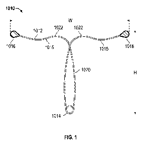
[0049] Referring to Figure 1, in one embodiment, a contraceptive
intrauterine
device (IUD) 1010 may include a shape memory, elongate member 1012 and two
tissue
-13-
CA 02881162 2015-02-06
WO 2014/028499
PCT/US2013/054743
contact members 1016, 1018 disposed at opposite ends of elongate member 1012.
Elongate member 1012 may include a spring portion 1014, typically but not
necessarily
disposed approximately at a midpoint between the opposite ends of elongate
member
1012, an expandable middle portion 1020, two arms 1015 extending from middle
portion
1020, and bends 1022 between middle portion 1020 and arms 1015. All or a part
of each
tissue contact member 1016, 1018 may comprise a tissue contact surface, in
other words,
a surface that typically contacts an inner wall of a uterus when IUD 1010 is
deployed in
the uterus.
[0050] Elongate
member 1012 is manufactured from a resilient, shape memory
material, such as but not limited to Nitinol (nickel titanium alloy), spring
stainless steel,
other shape memory metal alloys, shape memory polymers, or the like, and has a
default
(or -predetermined") expanded configuration as shown in Figure 1. Elongate
member
1012 may be compressed into a low profile, collapsed configuration, to
facilitate
preloading of IUD 1010 into a delivery sheath and delivery of IUD 1010 through
a cervix
via the sheath. When released from compression within the uterus, IUD 1010
springs back
into its default expanded configuration to allow tissue contact members 1016,
1018 to
contact the uterine wall and, by the force inherent in its shape memory
material, apply
sufficient pressure against the inner wall of the uterus either when seated in
its proper
position, when pushed downward in the uterus, or both, to maintain IUD 1010 in
position
within the uterus. In many cases, IUD 1010 may not spring back into its fully
expanded,
default configuration when delivered into the uterus, due to force applied
upon it by the
uterine wall. Thus, it is possible to discuss an "expanded configuration" of
IUD 1010
without necessarily meaning that it is fully expanded to its default
configuration.
[0051] In some
embodiments, IUD 1010 may be configured to assume a
partially collapsed configuration, in which the uterine wall has pushed the
two tissue
contact members 1016, 1018 together to cause middle portion 1020 to expand
laterally.
This partially collapsed configuration is described in further detail below.
Generally, this
configuration may occur when forces applied by the uterine wall cause IUD 1010
to
migrate slightly in an inferior direction (i.e., toward the cervical os). As
middle portion
1020 expands, it may help prevent further inferior migration by contacting the
inner uterine
wall and thus acting as a stop mechanism.
-14-
CA 02881162 2015-02-06
WO 2014/028499
PCT/US2013/054743
[0052] In its fully
expanded configuration, such as in Figure 1, (or when
partially expanded) IUD 1010 in some embodiments applies outwardly directed
pressure
against the uterine wall that is sufficient only to help maintain IUD 1010 in
a desired
location in the uterus and prevent or at least limit inferior migration. In
alternative
embodiments. IUD 1010 may apply a greater amount of pressure against the
uterine wall,
such that the applied pressure helps facilitate or enhance the contraceptive
effect. Various
embodiments of IUD 1010 described herein may thus be "pressure-applying" or
"non-
pressure-applying," when they are seated at their proper position, but in
either case they
will be configured to provide effective contraception. Thus, any particular
embodiment
described herein should not be interpreted to limit the claims to a particular
amount of
pressure applied to a uterus, unless such limitation is specifically set forth
in a claim. It
will further be appreciated that the amount of pressure applied by the device
against the
uterine wall will depend on the amount of device compression caused by the
uterine wall,
which will change depending on the width of the default expanded configuration
of the
device and the normal width of the uterine cavity at the location where the
device is
positioned. As explained further below, this outward pressure may be at or
near zero
when the device is properly positioned, and may increase if the device
migrates downward
to a narrower portion of the uterine cavity. This increase in compression as
the device
moves downward can help maintain the device in its proper position, even when
little to no
pressure is applied by the device when properly positioned, because the lowest
energy
state for the device corresponds to the less expanded configuration (or
completely
expanded default configuration) associated with proper placement. This can
also help the
device migrate to the proper position even if placed lower in the uterine
cavity upon initial
insertion.
[0053] As
illustrated in Figure 1, in one embodiment, spring portion 1014 is
disposed at the vertex (or bottom) of elongate member 1012, middle portion
1020 extends
upward from spring portion 1014 in approximately an elongate oval shape,
elongate
member 1012 crosses over itself and forms bends 1022, and then it extends into
arms
1015. Although this configuration is described in reference to this
embodiment, IUD 1010
may have any of a number of different expanded configurations in alternative
embodiments. Furthermore, although the term "spring portion" is used to
describe a
portion of elongate member 1012 that helps confer laterally directed pressure
to tissue
-15-
CA 02881162 2015-02-06
WO 2014/028499
PCT/US2013/054743
contact members 1016, 1018, spring portion 1014 is not necessarily a spring.
In many of
the embodiments, for example, spring portion 1014 is simply a midpoint of
elongate
member 1012 that is formed as a loop. In other embodiments, spring portion
1014 may
have any of a number of different shapes.
[0054] IUD 1010 may
be said to have a wingspan (or "width") W, as measured
from a tip of one tissue contact member 1016 to a tip of the other tissue
contact member
1018. IUD 1010 may also be said to have a height (or "length") H. as measured
from the
bottom of spring portion 1014 to the tops of tissue contact members 1016,
1018.
Wingspan W and height H are generally selected to provide IUD 1010 with a
desired
amount of laterally directed pressure at tissue contact members 1016, 1018, so
that IUD
1010 will maintain itself in a given location within the uterus and exert
sufficient pressure
to promote contraception. In one embodiment, for example, IUD 1010 may have a
height
H of between about 10 to 50 mm, with about 28 mm and about 32 mm being
advantageous, and a wingspan W of between about 18 mm and about 54 mm, with
about
30 to about 34 mm being found advantageous in some implementations.
Alternative sizes
may be provided to enhance the effectiveness of IUD 1010 in different female
anatomies,
but because IUD 1010 is sufficiently resilient and the uterus is typically a
closed space,
IUD 1010 is generally a "one size fits all- device.
[0055] As just
mentioned, the uterus (or "uterine cavity-) is generally not an
open space. Even though the uterus is typically illustrated as an open space,
such as in
Figures 2A-2F, this is simply a schematic illustration, because the uterus
itself is a closed
space. IUD 1010 should, therefore, have sufficient laterally directed pressure
when
released from a delivery device within the uterus to expand within the closed
uterine
cavity. The uterus is also typically a moist environment, so IUD 1010 should
have
sufficient resiliency to overcome any surface tension that might hold the
opposed surfaces
of the inner wall of the uterus together. In embodiments in which substances
(copper,
hormone, etc.) are not included, the IUD 1010 may be configured to apply
sufficient
laterally directed pressure when seated in its proper position to promote
contraception
without the presence of any additional contraceptive substances. It is
believed that
pressure applied to the inner uterine wall by tissue contact members 1016,
1018 in these
implementations may by itself disrupt the uterine environment in such a way to
cause a
spermicidal effect, thus preventing conception. The pressure exerted against
the uterine
-16-
CA 02881162 2015-02-06
WO 2014/028499
PCT/US2013/054743
wall by IUD 1010 may cause an inflammatory response, ischemia, compression of
the
spiral artery and/or a combination thereof, and any or all of these may help
promote
contraception. Devices which include no
additional contraceptive substances are
illustrated in Figures 1 through 4. Devices which include additional
contraceptive
substances are illustrated in Figures 5 through 10 and 12. Depending on
whether such
additional substances are provided, the optimal size and compression
characteristics may
be different.
[0056] Finally, IUD 1010 should
have sufficient laterally directed pressure to
inhibit inferior migration of the device within the uterus or expulsion of the
device from the
uterus. As is described in greater detail below, IUD 1010 likely has the
greatest
contraceptive effect when it resides in a certain portion of the uterus, so
ideally IUD 1010
will have sufficient outwardly directed pressure at at least some positions
within the
uterine cavity to prevent inferior migration or expulsion of the device. In
some
embodiments. IUD 1010 also has a configuration and applies sufficient force to
promote
superior migration of the device after delivery. At the same time, another
objective of
IUD 1010 is to prevent perforation of the uterine wall, so IUD 1010 should not
have an
excessive amount of outwardly directed pressure.
[0057] IUD 1010 generates
laterally directed, expansile pressure due to the
nature of its resilient, shape memory material (typically but not necessarily
Nitinol), the
diameter of its material, and its default, expanded shape and size, including
spring portion
1014. Spring portion 1014 may in some embodiments be an actual spring or
looped
portion of elongate member 1012, while in alternative embodiments it may be
any of a
number of other suitable shapes that help confer laterally directed pressure
to elongate
member 1012. This laterally directed pressure pushes tissue contact members
1016, 1018
against the uterine wall with sufficient pressure that they first move along
the wall to a
desired location for promoting contraception and then maintain their position
on (or
"adhere to") the wall at that location. IUD 1010 may also have a shape, size,
lateral
pressure, and size and shape of tissue contact members 1016, 1018 that help
prevent tissue
contact members 1016, 1018 from advancing (or "migrating") into the fallopian
tubes. It
may be advantageous for IUD 1010 to avoid entering the fallopian tubes,
because this may
facilitate removal of IUD 1010 when desired. Delivery, adherence to the
uterine wall and
other characteristics of IUD 1010 are described in further detail below. As
mentioned, in
-17-
CA 02881162 2015-02-06
WO 2014/028499
PCT/US2013/054743
one embodiment, elongate member 1012 is made of Nitinol. In various
embodiments, the
diameter of elongate member 1012 may be selected to help provide a desired
amount of
lateral pressure generation when the device is in the default expanded
configuration of
Figure 1. For example, in some embodiments, elongate member 1012 may be a
Nitinol
wire with a diameter of between about 0.010" and about 0.025", between .015"
and .017"
or between about 0.014" and about 0.015".
[0058] In
alternative embodiments, resilient materials other than Nitinol may be
used, such as other shape memory metal alloys, spring stainless steel or the
like. Nitinol is
typically preferred, however, due to its ability to remain in a compressed
configuration
(such as in a delivery catheter) for long periods of time, fully spring back
into its expanded
configuration, and maintain a constant but gentle pressure against the uterine
wall for
many years of useful life of IUD 1010. The material properties of a Nitinol
IUD 1010
allow it to be compressed into a collapsed or low profile configuration for
storage in a
delivery device, stored in that configuration for long periods of time, and
then delivered
out of the delivery device to assume its default, expanded configuration.
Other resilient
materials typically do not retain their full resilient properties over time in
this way,
although to the extent other materials would serve this purpose they may be
used in
alternative embodiments. Storing and/or packaging IUD 1010 within a delivery
device
makes its use easier, because the end user (typically a physician or
physician's assistant) is
not required to load the device into the delivery device. By contrast,
currently available
IUDs typically must be loaded into their delivery devices by a physician or
physician's
assistant before use. Initiation and/or increase in compression from inferior
migration can
produce gentle lateral pressure along the inner uterine wall inhibiting
expulsion of IUD
1010 out of the uterus, which is one of the potential complications of
currently available
IUDs.
[0059] Tissue
contact members 1016, 1018 may be comprised of any of a
number of suitable materials and may have a number of different sizes and
shapes. In some
embodiments. IUD 1010 may include tissue contact members 1016, 1018 made of
different or the same material as elongate member 1012. Alternatively, an IUD
may
include "tissue contact surfaces" that are part of elongate member 1012. These
tissue
contact surfaces may also be referred to as "tissue contact points" or "end
points." Tissue
contact members 1016, 1018 also generally include tissue contact surfaces
(i.e., a portion
-18-
CA 02881162 2015-02-06
WO 2014/028499
PCT/US2013/054743
of each tissue contact member 1016, 1018 that contacts the uterine wall).
Thus, the
phrases -tissue contact members,- 'tissue contact surfaces," -tissue contact
points" and
"end points" may sometimes be used herein interchangeably and should not be
interpreted
to limit the scope of the invention as set forth in the claims.
[0060] Generally,
the material, size and shape of tissue contact members 1016,
1018 are selected to prevent, or at least reduce the tendency for, tissue in-
growth of tissue
contact members 1016, 1018 into uterine wall tissue while also preventing
inferior
migration or expulsion of IUD 1010. Tissue in-growth prevention is important
for
facilitating later removal of IUD 1010 from the uterus if and when desired.
This prevention
of tissue in-growth is in direct contrast to a number of prior art permanent
contraception
or sterilization devices that purposely try to promote tissue in-growth, for
example to
permanently attach a device within the fallopian tubes. IUD 1010, in contrast,
is usually
easily removed and does not permanently adhere to the uterine wall. In one
embodiment,
tissue contact members 1016, 1018 may be made of a high density polyethylene.
In
alternative embodiments, tissue contact members 1016, 1018 may be made of any
of a
number of alternative, typically non-porous materials, such as but not limited
to metals,
plastics, elastomers such as silicone, or combinations thereof Furthermore,
tissue contact
members 1016, 1018 may be coated, such as with a coating to prevent tissue in-
growth, or
may be impregnated with various medications or other substances, such as but
not limited
to hormone, spermicide or the like. Tissue contact members 1016, 1018 may also
be made
of (or coated with) an echogenic material to facilitate visualization of IUD
1010 using
transvaginal ultrasound or other visualization techniques.
[0061] Tissue
contact members 1016, 1018 may have any suitable size and
shape but are generally configured to apply a desired amount of pressure to
the uterine
wall to maintain the position of IUD 1010, in some embodiments to promote
contraception, and to prevent tissue in-growth, without causing pain or
uterine wall
perforation, a well known risk of currently available intrauterine devices.
Tissue contact
members 1016, 1018 may also be sized so that they can be effectively delivered
through a
low profile delivery device without pain to the patient. To achieve these
goals, tissue
contact members 1016, 1018 according to one embodiment have a diameter of
between
about 1 mm and about 8 mm, and preferably between about 2 mm and about 4 mm,
and
even more preferably between about 2.5 mm and about 3.5 mm. Tissue contact
members
-19-
CA 02881162 2015-02-06
WO 2014/028499
PCT/US2013/054743
1016, 1018 according to this embodiment may have a length of between about 3.0
mm and
about 5.0 mm, and preferably between about 3.5 mm and about 3.6 mm. Also
according to
one embodiment, each tissue contact member 1016, 1018 has a surface area of
between
about 30 mm squared and about 45 mm squared, and preferably between about 31
mm
squared and about 32 mm squared. Providing tissue contact members 1016, 1018
with a
relatively large surface area (while keeping them small enough to fit within a
delivery
device) may help prevent uterine wall perforation and in-growth, while still
allowing for
the application of a desired amount of laterally directed pressure against the
uterine wall.
[0062] Referring
now to Figures 2A-2F, a portion of the female reproductive
anatomy is shown in schematic form in cross-section, and a method for
delivering IUD
1010 to a uterus U is illustrated. As shown in Fig. 2A, the vagina V leads
into the cervix
C, which in turn leads into the uterus U (illustrated schematically as an open
cavity). The
uterus U has an inner wall W, which in this application is referred to simply
as the uterine
wall. Two fallopian tubes F branch off of the uterus U. During the natural
reproductive
cycle, eggs travel down the fallopian tubes F to be fertilized by sperm
(typically within a
fallopian tube F), and the fertilized egg then implants on the uterine wall W
to grow into a
fetus. IUD 1010 works primarily or exclusively by producing a "hostile
environment" in
the uterus U for sperm and thus preventing fertilization, or secondarily, if
fertilization
occurs, by blocking implantation.
[0063] With
reference to Figure 2B, as a first step in a method for IUD
delivery, an IUD delivery device 1020 containing IUD 1010 (not visible in
Figure 2B) may
be advanced through the cervix C into the uterus U. While housed in delivery
device 1020,
IUD 1010 is in a collapsed, low profile configuration to facilitate its
passage through the
cervix C. In some embodiments, such as the one pictured, IUD 1010 may be
completely
contained within delivery device 1020 during advancement of delivery device
1020
through the cervix C. As will be described further below, IUD 1010 may be
preloaded into
a proximal end of delivery device 1020, due to its shape memory material. This
proximal
preloading allows delivery device 1020 to have a tapered distal tip 1021,
which facilitates
advancement of delivery device 1020 through the cervix C with little or no
pain or
discomfort. Proximal preloading of IUD 1010 into delivery device 1020 also
makes the
process easier for a user, since currently available IUDs must be pulled into
the distal end
of a delivery device by the physician or physician's assistant prior to use.
Delivery device
-20-
CA 02881162 2015-02-06
WO 2014/028499
PCT/US2013/054743
1020 may take any of a number of suitable forms, typically including an outer
sheath and
an inner pusher member. One embodiment of a delivery device is described is
described in
further detail below with reference to Figure 10.
[0064] Figures 2C
and 2D show the next steps in an IUD delivery process,
according to one embodiment. Figure 2C illustrates IUD 1010 partially expelled
from
delivery device 1020 into the uterus U. In Figure 2D, IUD 1010 has been
completely
expelled from delivery device 1020 but is still in contact with a pusher
member 1022 of
delivery device 1020. At this point, tissue contact members 1016, 1018 are
contacting the
uterine wall W. In various embodiments, IUD 1010 may be expelled from delivery
device
1020 using any of a number of different techniques and mechanisms. In one
embodiment,
for example, pusher member 1022 may be held in a stable position, and a sheath
on
delivery device 1020 may be retracted to expose IUD 1010. Alternatively, a
sheath may be
held in a stable position and pusher member 1022 may be advanced to push IUD
1010 out
of the distal end of delivery device 1020. In another embodiment, pusher
member 1022
may be advanced while a sheath is retracted. In other alternative embodiments,
other
suitable means for expelling IUD 1010 from delivery device 1020 may be used.
100651 Comparing
the position of IUD 1010 in Figures 2C and 2D shows that
IUD 1010 may advance along the uterine wall W toward the fallopian tubes F
during
and/or after delivery to eventually seat (or "adhere") in an area just below
(or "inferior to-)
the fallopian tube openings. Alternatively, IUD 1010 may simply be delivered
directly to
the desired location within the uterus U rather than delivering it to an
initial location and
having it ride along the uterine wall W before seating at its final location.
The words "seat"
and "adhere" do not mean that IUD 1010 permanently attaches to the uterine
wall. In fact,
as previously mentioned, tissue contact members 1016, 1018 and IUD 1010 are
designed
to prevent tissue in-growth and permanent attachment to the uterine wall.
"Seating" and
"adhering" are thus generally used to simply mean maintaining a relative
position along the
uterine wall. Ideally, but not necessarily, each tissue contact member 1016,
1018 will seat
in an area of the uterine wall W within approximately 2 cm inferior of a
fallopian tube
opening, and preferably within approximately 1 cm inferior of a fallopian tube
opening.
This is believed to be an ideal area for IUD 1010 to reside for contraception,
although an
exact location for IUD 1010 within the uterus is not required.
-21-
CA 02881162 2015-02-06
WO 2014/028499
PCT/US2013/054743
[0066] Movement of
IUD 1010 along the uterine wall and adherence of IUD
1010 at a given location are caused by a combination of the amount of outward
pressure
produced inherently by IUD 1010, the size and shape of IUD 1010, the size,
shape and
physical characteristics of tissue contact members 1016, 1018, and the size
and shape of
the uterus U. IUD 1010 is configured to have enough outwardly directed
pressure and
other characteristics to make IUD 1010 adhere to the uterine wall W, typically
near the
fallopian tube orifices, without actually entering the fallopian tubes F. In
some
implementations, pressure applied to the uterine wall W by the IUD 1010 when
in its
proper position is believed to be at least one reason that IUD 1010 prevents
pregnancy.
The constant, gentle pressure applied to the uterine wall W is believed to
disrupt the
natural uterine environment. In alternative embodiments, described further
below, an IUD
may simply contact the uterine wall and not apply any significant amount of
pressure to the
wall. In these embodiments, in other words, the IUD contacts the uterine wall
with
sufficient force only to maintain positioning of the IUD, in which case the
IUD may
advantageously include some form of substance delivery mechanism (copper,
hormone,
etc.) to provide contraceptive effect.
[0067] In its fully
expanded, default configuration, IUD 1010 may have a
wingspan or width W (described previously), of between about 18 mm and about
54 mm,
depending upon the anatomical characteristics of the patient. The wingspan W
of IUD
1010 may be selected at least in part due to the distance between the uterine
wall W just
inferior to one fallopian tube F and the uterine wall W just inferior to the
opposite fallopian
tube F. For example, the average intra-ostial distance in nulliparous women is
29.2 mm,
and the average intra-ostial distance in parous women is 30.0 mm, so the IUD
wingspan
may in some embodiments be based at least in part on these measurements.
("Assessment
Of The Uterine Cavity And The Intraostial Distance Using
Hysterosalpingography",
Fertility and Sterility, Volume 88, Supplement 1, September 2007, Page S202,
J. G.
Bromer, F. Sanguinetti, M. Tal, P. Patrizio. Obstetrics, Gynecology, and
Reproductive
Sciences, Yale University School of Medicine, New Haven, Conn.; Department of
Radiology, Yale University School of Medicine, New Haven, Conn.).
[0068] As described
previously, when expanded, one embodiment of IUD 1010
applies laterally directed pressure against the uterine wall W via tissue
contact members
1016, 1018 to cause irritation/inflammation, ischemia, compression of arterial
structures,
-22-
CA 02881162 2015-02-06
WO 2014/028499
PCT/US2013/054743
and/or other effects that promote contraception. Additionally, IUD 1010 may
apply
sufficient pressure to slightly distort the shape of the uterine wall W, which
is believed to
further promote contraception. The amount of laterally directed pressure
applied to the
uterine wall W is important for proper functioning of IUD 1010, both for
adherence (and
thus migration and expulsion prevention), and also for the added effect of
uterine wall
distortion (at least in some embodiments with no additional contraceptive
substances). In
various embodiments, a range of the pressure applied by tissue contact members
1016,
1018 to the uterine wall is between about 0.002 pounds-pressure and about
0.025 pounds-
pressure, and may advantageously be between about 0.002 pounds-pressure and
about
0.015 pounds-pressure.
[0069] Referring to
Figure 2E, IUD 1010 is shown in place in the uterus U,
completely disconnected from delivery device 1020. At this point, delivery
device 1020
may be removed through the cervix C, leaving IUD 1010 in place, as shown in
Figure 2F.
IUD 1010 then remains in the uterus U for as long as desired to promote
contraception.
[0070] IUD 1010 may
be left in the uterus U permanently or may be removed
at any time. Because IUD 1010 is easily delivered and removed, it allows for
nonsurgical
contraception as an office procedure and without the need for surgery or the
necessity for
visualization either radiologically, ultrasonically, or with a hysteroscope.
IUD 1010 uses
radial pressure and inherent properties in its construction to promote
contraception, thus
eliminating the need for hormones or copper in the device. IUD 1010 also uses
radial
pressure prevent inferior migration or expulsion. As such, IUD 1010 may be
used for
permanent or temporary contraception. As described further below, although IUD
1010
does not require the use of hormones, copper or other substances, in
alternative
embodiments it may also be adapted for local delivery of these or other
therapeutic agents.
In other alternative embodiments, IUD 1020 may be configured to provide
contraceptive
effect primarily or exclusively via delivery of a substance (copper, hormone,
etc.) and not
via application of pressure. IUD 1010 may also be used, in some embodiments,
for
treatment of one or more conditions such as abnormal uterine bleeding and/or
pelvic pain,
in addition to providing contraception.
100711 Referring
now to Figure 3, in another embodiment, a contraceptive
device (or -IUD") 2100 may have a similar configuration to that described
above, but may
have an elongate shape memory member 2102 formed into loops at opposite ends
to
-23-
CA 02881162 2015-02-06
WO 2014/028499
PCT/US2013/054743
provide tissue contact surfaces (or "end points-) 2108a, 2108b, rather than
having tissue
contact members attached to elongate member 2102. In all other aspects, the
embodiment
of IUD 2100 in Figure 3 is the same as the embodiment of IUD 1010 in Figure 1.
As with
the previously described embodiment, contraceptive device 2100 may include
elongate
member 2102, an expandable middle portion 2104, a spring portion 2106, two
bends 2110
and two arms 2112. In various embodiments, elongate member 2102 may have a
predominantly flat (or "two-dimensional") configuration, as shown.
Alternatively, elongate
member 2102 may have a more three-dimensional configuration (not shown). For
example,
one or more portions of elongate member 2102 may be curved or bent, which in
some
embodiments may help elongate member 2102 conform to a curved shape of a
uterus.
[0072]
Contraceptive device 2100 is shown, in Figure 3, in its fully expanded,
unconstrained, default configuration. Contraceptive device 2100 may also be
compressed
into a long, thin configuration for placement within a delivery device (not
shown), such as
a delivery catheter or sheath, by pulling/pushing tissue contact surfaces
2108a, 2108b
upward, away from spring portion 2106. The delivery device may be sufficiently
small so
that it can be passed through a cervix without causing pain or discomfort and
without
requiring mechanical dilation, anesthesia (topical, local or general) or
expansion of the
cervix, cervical canal or internal or external cervical os. In some
embodiments, for
example, contraceptive device 2100 may be compressible/collapsible to a
diameter that fits
within a delivery sheath having an inner diameter of between about 2.50 mm and
about
3.00 mm and more preferably between about 2.70 mm and about 2.90 mm, and an
outer
diameter of between about 2.80 mm and about 3.40 mm and more preferably
between
about 2.95 mm and about 3.20 mm.
[0073] When
contraceptive device 2100 is released from its delivery catheter
into the uterus, it expands to a configuration approximately like the
configuration shown in
Figure 3. Typically, tissue contact surfaces 2108a, 2108b will help device
2100 adhere to
uterine wall tissue to remain in place near but not in the fallopian tubes.
However, if
contraceptive device 2100 begins to migrate down (or out of) the uterus, the
uterine wall
will pressure tissue contact members 2108a, 2108b together, thus pushing out
the sides of
middle portion 2104. The expanded sides of middle portion 2104 will then
provide
increased mechanical resistance, including but not limited to, contacting the
uterine wall
and helping to prevent or resist migration. The expansion of middle portion
2104 is
-24-
CA 02881162 2015-02-06
WO 2014/028499
PCT/US2013/054743
directly proportional to the amount of compression placed on tissue contact
surfaces
2108a and 2108b by the uterine wall, and thus the relative amount of
contractility of the
uterine wall. Thus, in some embodiments, the separation distance of middle
portion 2104
(and/of tissue contact surfaces 2108a, 2108b) may be used as a measurement of
uterine
contractility. This is described further with reference to Figures 4A and 4B.
[0074] Elongate
member 2102 may be made of any suitable shape memory
material, such as but not limited to Nitinol, other shape memory metal alloys
or shape
memory polymers. Tissue contact surfaces 2108a, 2108b may be made of the same
material or a different material as elongate member 2102. Typically, tissue
contact surfaces
2108a, 2108b will be made of a material that resists slipping on the
intrauterine wall but
that also resists tissue ingrowth, as described previously. In some
embodiments, tissue
contact surfaces 2108a, 2108b may comprise balls of formed material, such as a
polymer,
deposited on the ends of elongate member 2102. In other embodiments, such as
the one in
Figure 3, tissue contact surfaces 2108a, 2108b are simply portions of elongate
member
2102. Generally, the term "end points" or "tissue contact members" or "tissue
contact
surfaces" or other similar terms are used herein to refer to portions of an
IUD that contact
the uterine wall when the IUD is in place. In many embodiments, the "tissue
contact
members- are at the ends of an elongate member and are the primary contact
points of the
IUD with the uterus. In some embodiments, however, such as the embodiment just
described, IUD 2100 may include additional tissue contact surfaces or portions
(for
example expandable middle portion 2104), as will be described further below.
Whether the
term used in relation to a particular embodiment is "end points" or "tissue
contact
members" or "tissue contact surfaces" or some other similar term should not be
interpreted
to limit the scope of the invention as it is defined by the claims.
[0075] Forming
tissue contact surfaces 2108a, 2108b as loops of elongate
member 2102, as in the embodiment shown in Figure 3, may be advantageous for a
number of reasons. One reason is that such a configuration will allow IUD 2100
to be
collapsed down to a very small cross-sectional diameter for insertion into a
delivery
device, because the loops of elongate member 2102 can easily overlap. In some
embodiments, for example, contraceptive device 2100 may be
compressible/collapsible to a
diameter that fits within a delivery sheath having an inner diameter of
between about 2.50
mm and about 3.00 mm and more preferably between about 2.70 mm and about 2.90
mm,
-25-
CA 02881162 2015-02-06
WO 2014/028499
PCT/US2013/054743
and an outer diameter of between about 2.80 mm and about 3.40 mm and more
preferably
between about 2.95 mm and about 3.20 mm.
[0076] Referring
now to Figures 4A and 4B, contraceptive device 2100 is
shown immediately after being delivered into a uterus (Figure 4A) and after
slight
migration down the uterine wall (Figure 4B). In Figure 4A, device 2100 has
been
delivered, and tissue contact surfaces 2108a, 2108b are contacting the inner
uterine wall U
near but not within the fallopian tubes. In this position, tissue contact
surfaces 2108a,
2108b may apply pressure to the uterine wall U and are in an optimal position
to prevent
conception. In most cases, IUD 2100 will remain in this position or very close
to it. In
many cases, in fact, IUD 2100 may be delivered inferiorly and migrate
superiorly,
sometimes contacting the fundus of the uterus U, as will be described in
further detail
below. In some cases, however, and with reference now to Figure 4B,
contraceptive
device 2100 may be subject to contractile pressures of the uterus which may
cause the
device to slide (or "migrate") down the uterine wall U while remaining within
the uterine
cavity. Significant migration of any intrauterine device or ultimate expulsion
of the device
out of the uterus is obviously not desirable. Therefore, device 2100 is
configured such that
when end points 2108a, 2108b are forced closer together, middle portion 2104
expands or
bows outward to contact the uterine wall U along secondary contact surfaces
2112.
Secondary contact surfaces 2112 are simply lengths of middle portion 2104 that
may
contact the uterine wall upon expansion of middle portion 2104. Secondary
contact
surfaces 2112 and end points 2108a, 2108b thus act together to contact the
uterine wall U
and prevent inferior migration (or further inferior migration) of
contraceptive device 2100.
In this way, contraceptive device 2100 is configured to prevent its own
inferior migration
and/or expulsion out of the uterus.
[0077]
Additionally, the amount of separation distance of secondary contact
surfaces 2112 of middle portion 2104 is directly proportional to the amount of
compression of end points 2108a and 2108b, and thus proportional to a relative
amount of
uterine wall contractility. This separation or expansion of middle portion
2104 may thus be
used as a measurement tool for measuring approximate contractility of a
uterus. In one
embodiment, middle portion 2104 (or part of middle portion 2104) may be marked
with
one or more radiopaque markers or may be made radiopaque. to enhance
visualization and
thus facilitate measurement of uterine contractility. In other embodiments,
end points
-26-
CA 02881162 2015-02-06
WO 2014/028499
PCT/US2013/054743
2108a, 2108b may have enhanced radiopacity for the same purpose. In still
other
embodiments, both middle portion 2104 and end points 2008a, 2008b may be made
radiopaque or include radiopaque markers. A method may include visualizing the
separation of middle portion 2104 and approximating an amount of uterine
contractility
from the separation.
[0078] The IUD
embodiments described above may provide effective
contraception without the use of copper, Levonogestrel, other hormones or
other drugs or
substances. This may be advantageous in many circumstances, because any side
effects
potentially caused by such substances will be avoided by using a "substance-
free" IUD. In
some embodiments, however, it may be equally or even more advantageous to
provide an
IUD that delivers copper, hormone and/or one or more other substances in a
limited dose
to the uterus. For example, a focal substance delivery IUD according to one
embodiment
may deliver copper to a targeted area at or near each of the openings of the
fallopian tubes
and/or at or near a cervical os. Although some amount of copper will typically
permeate
most or all of the rest of the interior of the uterus, it may remain
concentrated in the
targeted areas of focal delivery. Thus, a lower dose of substance may be
delivered while
still providing effective contraception, since the delivery is targeted toward
areas of
enhanced contraceptive efficacy. In this way, a focal substance delivery IUD
may provide
contraception that is equal to or better than currently available devices
while reducing or
eliminating the side effects typically caused by such devices.
[0079] The IUD
embodiments described below employ shape memory material
to maintain contact with a uterine wall and also provide selective delivery of
copper to
targeted areas within the uterus. In alternative embodiments, any of the IUDs
described
above may be altered to include delivery of copper and/or one or more
alternative
substances. In some embodiments, an IUD may provide selective or targeted
delivery of
copper and application of uterine wall pressure to provide contraception. The
delivery of
lower dose copper or other substances described below may be generally
referred to as
"selective," -targeted," -focal," -localized" or the like. These terms
generally mean that a
substance is purposely delivered to one or more areas within the uterus in a
greater
concentration than it is delivered to other parts of the uterus. In summary,
the IUDs
described herein may provide contraception by the application of pressure, by
targeted
delivery of copper or other substance, or by both. Therefore, although a
number of IUD
-27-
CA 02881162 2015-02-06
WO 2014/028499
PCT/US2013/054743
embodiments are described herein as having a particular mechanism of
contraceptive
action, in alternative embodiments they may be modified to have additional or
other
mechanisms also described herein.
[0080] Referring
now to Figure 5, in another embodiment, a contraceptive
device (or "IUD") 2200 similar to the one shown in Figure 3 may include an
elongate
shape memory member 2202 having two tissue contact surfaces (or "end points")
2208a,
2208b. Elongate member 2202 may have a two-dimensional (i.e., predominantly
flat)
configuration, as shown, or alternatively may have a more three dimensional
(i.e., slightly
bent out of plane) configuration, as discussed above. Elongate member 2202 may
include a
middle portion 2204, a spring portion 2206, and bends 2210 between the middle
portion
2204 and the tissue contact surfaces 2208a, 2208b. Spring portion 2206 is
generally
located at an approximate midpoint of the length of elongate member 2202
i.e., at the
bottom of IUD 2200. Middle portion 2204 is capable of expanding to contact the
uterine
wall and limit inferior migration and expulsion. as described previously.
[0081] In this
embodiment, four focal substance delivery members in the form
of copper sleeves 2212 are disposed over elongate member 2202 close to tissue
contact
surfaces 2208a, 2208b. Copper sleeves 2212 may deliver a small amount of
copper to the
uterine wall near one of the ideal locations for contraceptive effect¨i.e.,
near and just
below the fallopian tubes. By providing focal delivery of copper,
contraceptive device
2200 may provide the beneficial contraceptive effect of copper without the
side effects
often seen with currently available copper IUDs¨i.e., excessive and/or non-
menstrual
bleeding. Such focal delivery may also be described as "concentrated,"
"selective,"
"localized," "targeted" or the like, as mentioned above. Copper sleeves 2212
generally
cover only a minority of elongate member 2202, and focal delivery of copper
thus achieves
the desired contraceptive effect while delivering a lower overall dose of
copper to the
uterus, compared with currently available IUDs. For example, copper sleeves
2212 of
contraceptive device 2200 may have an exposed surface area of no more than
about 200
square millimeters, and more ideally no more than about 150 square
millimeters, and even
more ideally no more than about 125 square millimeters. In the embodiment
shown in
Figure 5, for example, the copper sleeves 2212 have a surface area of about
125 square
millimeters. By comparison, currently available IUDs typically have copper
measurements
of about 380 square millimeters _________________________________ i.e., over
three times as much as the surface area of
-28-
CA 02881162 2015-02-06
WO 2014/028499
PCT/US2013/054743
copper sleeves 2212. By delivering copper locally, near an ideal location
within the uterus,
contraceptive device 2200 may accomplish the objective of copper without as
many
bleeding side effects.
[0082] In an
alternative embodiment, copper may also be attached to
contraceptive device 2200 at or near spring portion 2206. Such copper may be
attached,
for example, in the form of one or more sleeves or one or more wires wrapped
around
elongate member 2202. Copper located in this area on contraceptive device 2200
may be
advantageous, because when contraceptive device 2200 is implanted, that
portion of the
copper will be located near to the cervical os (the opening of the cervix into
the uterus).
Copper disposed in this area will help stop sperm from proceeding farther into
the uterus.
In another alternative embodiment (not shown), copper may be included at or
near spring
portion 2206 and not near end points 2208a, 2208b. In alternative embodiments,
sleeves
2212 may be replaced by any other suitable substance delivery device(s), such
as but not
limited to copper wire(s), drug delivery depot(s), drug coatings, drug eluting
carriers, or
the like.
[0083] In yet other
alternative embodiments (also not shown), copper sleeves
2212 may be used along with one or more hormone delivery devices, which may
contain
or be coated or impregnated with Levonorgestrel or any other suitable hormone,
which
may be released over time into the uterus. When a combination of copper and
hormone is
used, it may be possible to lower the doses of both the copper and the hormone
to very
low levels while still providing the desired contraceptive effect. In various
embodiments,
any suitable hormone delivery device (or devices) may be attached to elongate
member
2202, as desired.
[0084] Referring
now to Figures 6A and 6B, another alternative embodiment
of a focal substance delivery contraceptive device (or "IUD") 2300 is shown,
in front and
perspective views, respectively. In this embodiment, IUD 2300 may again
include an
elongate shape memory member 2302 having two tissue contact surfaces (or "end
points")
2308a, 2308b. Elongate member 2302 may have a two-dimensional (i.e.,
predominantly
flat) configuration, as shown, or alternatively may have a more three
dimensional (i.e.,
slightly bent out of plane) configuration. Elongate member 2302 may include a
middle
portion 2304, a spring portion 2306, and bends 2310 between middle portion
2304 and
tissue contact surfaces 2308a, 2308b. Again, spring portion 2306 is generally
located at an
-29-
CA 02881162 2015-02-06
WO 2014/028499
PCT/US2013/054743
approximate midpoint of the length of elongate member 2302¨i.e., at the bottom
of IUD
2300. Attached to spring portion 2306 is a retrieval string 2305, which may be
a suture
material or the like for retrieving the device 2300 from the uterus.
[0085] This
embodiment includes copper sleeves 2312 near each of tissue
contact surfaces 2308a, 2308b and additional copper sleeves 2314 near spring
portion
2306. Thus, the IUD 2300 may provide focal delivery of copper to areas of the
uterus at
or near openings of the fallopian tubes as well as at or near the cervical os.
In one
embodiment, the total surface area of copper sleeves 2312, 2314 may be no more
than
about 200 square millimeters and even more ideally no more than about 150
square
millimeters. This embodiment includes four substance delivery sleeves 2312
near tissue
contact surfaces 2308a, 2308b and two sleeves 2314 near spring portion 2306.
In
alternative embodiments, any other suitable number of sleeves may be included,
such as
between 1 and 20 sleeves. In other alternative embodiments, sleeves 2312, 2314
may be
replaced with some other form of substance delivery device or mechanism, such
as but not
limited to wires, coatings, apertures in elongate member 2302 that leak a
substance,
permeable materials, beads coated or impregnated with a substance, or the
like.
Additionally, in various embodiments, sleeves 2312, 2314 may be either loosely
or tightly
affixed to elongate member 2302, so that they may be free to move in some
embodiments
and may be fixedly attached in others.
[0086] With
reference now to Figures 7A and 7B, as described previously, the
various embodiments of the IUD described herein are configured to resist
and/or limit
inferior migration and expulsion of the IUD from a uterus. Some or all of the
embodiments
may also have a tendency, due to their configuration and shape memory
material, to
migrate superiorly within a uterus (i.e., toward the top or "fundus" of the
uterus). For
example, as shown in Figure 7A, the IUD 2300 may be delivered into a uterus U
in a
relatively inferior location (for example, just beyond the cervical os 0). In
this location, the
device 2300 and its substance delivery members may be located relatively far
from the
openings of the fallopian tubes F. As shown in Figure 7B, however, the device
2300 may
tend to expand and move superiorly up the uterus U to a position closer to the
fallopian
tube F openings. This second, migrated position may be more effective for
contraception.
However, in either location, the copper sleeves 2312, 2314 are located near
the openings
of the fallopian tubes F and the cervical os 0, thus providing focal substance
delivery in
-30-
CA 02881162 2015-02-06
WO 2014/028499
PCT/US2013/054743
those areas. Thus, the embodiments described herein may facilitate delivery of
an IUD,
because it is possible to simply place the device just within the uterus and
allow it to
migrate to a more desirable location within the uterus. This will likely be
easier than trying
to position a device in an ideal location during initial delivery, which may
require
visualization, increased manipulation and potentially discomfort to the
patient.
[0087] With
reference now to Figures 8A and 8B, in some embodiments, IUD
2300 may be delivered to (or may migrate to) a first, relatively superior
location in the
uterus, as shown in Figure 8A. At this location IUD 2300 may assume is fully
expanded
(or nearly fully expanded) configuration. At some later point, IUD 2300 may
migrate
slightly inferiorly, as shown in Figure 8B, thus causing copper sleeves 2312
(or other
substance delivery devices) to move together to form a continuous line
approximately
horizontally across the uterus U. This approximately horizontal line of copper
sleeves 2312
may act as an approximately horizontal, linear blockade to help block sperm
from traveling
through the uterus U toward the fallopian tubes F. At the same time, the other
copper
sleeves 2314 are still located at or near the cervical os 0 to further enhance
contraception.
[0088] Referring
now to Figures 9A-9D, another alternative embodiment of a
focal substance delivery contraceptive device (or "IUD") 2500 is shown, in
front, bottom,
side and perspective views, respectively. In this embodiment, IUD 2500 has all
the features
of the embodiment of Figures 6A and 6B, but also includes additional copper
sleeves.
Thus, IUD 2500 includes elongate shape memory member 2502 having two tissue
contact
surfaces (or "end points") 2508a, 2508b. Elongate member 2502 includes a
middle portion
2504, a spring portion 2506, and bends between middle portion 2504 and tissue
contact
surfaces 2508a, 2508b. Again, spring portion 2506 is generally located at an
approximate
midpoint of the length of elongate member 2502¨i.e., at the bottom of IUD
2500.
Attached to spring portion 2506 is a retrieval string 2505, which may be a
suture material
or the like for retrieving the device 2500 from the uterus.
[0089] In the
embodiment shown, IUD 2500 includes copper sleeves 2512 near
each of the tissue contact surfaces 2508a, 2508b and additional copper sleeves
2514 near
spring portion 2506, as in Figures 6A and 6B. In this embodiment, however,
there are four
additional copper sleeves 2514 near spring portion 2506, rather than two.
Additionally,
there are two added copper sleeves 2513, positioned on the loop formed at the
opposite
ends of elongate member 2502. Thus, the IUD 2500 may provide focal delivery of
copper
-31-
CA 02881162 2015-02-06
WO 2014/028499
PCT/US2013/054743
to areas of the uterus at or near openings of the fallopian tubes as well as
at or near the
cervical os via a total of ten copper sleeves 2512, 2513, 2514. In one
embodiment, the
total exposed surface area of the copper sleeves 2512, 2513, 2514 may be no
more than
about 200 square millimeters and even more ideally no more than about 150
square
millimeters.
[0090] With
reference now to Figure 10, another alternative embodiment of a
focal substance delivery contraceptive device (or "IUD") 2600 similar to the
one shown in
Figures 6A and 613, and also including some of the extra copper sleeves of
Figures 9A-9D
is illustrated. This embodiment may include an elongate shape memory member
2602
having two tissue contact surfaces (or "end points") 2608a, 2608b. Elongate
member
2602 may have a two-dimensional (i.e., predominantly flat) configuration, as
shown, or
may have a more three dimensional (i.e., slightly bent out of plane)
configuration.
Elongate member 2602 may include a middle portion 2604, a loop portion 2606
disposed
at the vertex (or bottom ) of elongate member 2602, and bends 2610 between
middle
portion 2604 and tissue contact surfaces 2608a, 2608b. Attached to loop
portion 2606 is
a retrieval string 2605, which may be a suture material or the like for
retrieving the device
2600 from the uterus. The device 2600 includes copper sleeves 2612 near each
of the
tissue contact surfaces 2608a, 2608b and additional copper sleeves 2614 near
loop portion
2606, as described with respect to the device 2300 depicted in Figures 6A and
6B.
[0091] In this
embodiment, the bottom loop portion does not form any turns of
a spring structure. Instead, to generate the resilience in the arms of the
device as in the
other embodiments described herein, this embodiment includes twists 2616 along
the
middle portion 2604 of the arms as they extend from the tissue contact
surfaces toward the
loop portion 2606. Twists may be formed when the two arms of the elongate
member
2602 cross each other more than once in a longitudinally extending helix
containing
multiple turns that run in series from closer to the loop portion 2606 outward
along the
arms until the arms diverge again from the twisted portion to form the
opposing ends of
the elongate member. Figure 10 shows three twists 2616, where each twist of
Figure 10
corresponds to an additional 180 degree rotation of wire orientation around
the other.
However, other numbers of twists (e.g., 1-5, 6-10, greater than 10) are also
possible. In
this embodiment, the twists 2616 act as the "spring portion" to confer
laterally directed
pressure to tissue contact surfaces 2608a, 2608b.
-32-
CA 02881162 2015-02-06
WO 2014/028499
PCT/US2013/054743
[0092] It may be
desirable to be able to easily modify the properties of the
elongate member 2602. For example, the anatomical dimensions or
characteristics of the
uterus or medical conditions of a patient may call for adjustments to the
outward force
produced by the device 2600. In such applications, the location of the twists
along the
middle portion 2604, the number of the twists 2616, and the tightness of the
twists 2616
may be used to provide variability in the properties of the device 2600. For
example,
increasing the number of twists 2616 may increase the stiffness of the
elongate member
2602; and decreasing the number of twists 2616 may decrease the stiffness of
the elongate
member 2602. For another example, increasing the tightness of the twists 2616
may
increase the stiffness of the elongate member 2602. Decreasing the tightness
of the twists
2616 may decrease the stiffness of the elongate member 2602. Moving the twists
2616 up
along the middle portion 2604 may increase the stiffness of the elongate
member 2602; and
moving the twists down along the middle portion 2604 may decrease the
stiffness of the
elongate member 2602. With the device of Figure 10, a variety of differently
configured
devices can be made available to physicians to apply in the appropriate
circumstances. The
variability provided by the twists also allows much easier and more continuous
customization of properties by merely modifying the nature of the twists,
rather than the
thickness or material of the wire itself to produce similar variations in
properties. Wires
come in standard sizes and materials, and if some intermediate is desired, the
expense can
make producing such a modified device impractical. Controlling properties of
the device
with the properties of the twists 2616 resolves this issue.
[0093] Figure 11
illustrates force vs. displacement curves for exemplary
contraceptive devices such as shown in the above Figures that have high rates
of stable
proper placement in the uterus. Lines 2714 and 2716 on Figure 11 show measured
force
at various displacements between 0.0 and 0.3 inches of displacement for two
different
devices manufactured with the same wire diameter and device configuration
which has
been found to have desirable stability characteristics. The measure of
displacement here is
the reduction in the distance between the ends of the two arms. To make the
measurement
illustrated in Figure 11, a device may have the end of one arm placed against
a solid
unmoving support, and the other arm may be pushed (or pulled) toward the
supported arm
with a force gauge. The applied force as a function of movement from the
default
unconstrained configuration is recorded. The solid line 2712 is a mean of the
force as a
-33-
CA 02881162 2015-02-06
WO 2014/028499
PCT/US2013/054743
function of displacement for measurements over many devices of the same
configuration as
lines 2714 and 2716. The waviness of the lines is generally due to noise in
the
measurement.
[0094] The general
steepness of the slope of the force-displacement curve is a
measure of the stiffness of the "spring" that pushes the ends of the two arms
outward
against a compressing force such as the uterine wall. Through testing a
variety of designs,
the applicant's clinical experience has shown that devices with a stiffness
requiring
relatively large forces for relatively small displacements, wherein the force-
displacement
curve for the device enters region 2720 on the upper left of the graph of
Figure 11, tend to
become embedded in the uterine wall after implantation with an excessive
frequency. This
is not desirable as it interferes with later device extraction. In addition,
devices with
relatively large displacement at relatively low compression forces, wherein
the force-
displacement curve for the device enters region 2730 on the lower right of the
graph of
Figure 11, tend to migrate downward after implantation with an excessive
frequency. This
is not desirable as the device is no longer properly positioned after such
migration and may
be expelled completely.
[0095] There is of
course no bright line between devices that do or don't
become embedded, or devices that do or don't migrate downward after
implantation.
However, it has been concluded from clinical and laboratory device testing
that for devices
having high likelihood for stable and/or slightly upwardly mobile implantation
characteristics and with low likelihood of becoming embedded in the uterine
wall, the
force-displacement curve of an intrauterine contraceptiNe device with opposed
compressible tissue contact surfaces should pass through at least one of
regions 2706 and
2708 of Figure 11, preferably both regions 2706 and 2708 of Figure 11 or both
regions
2706 and 2710 of Figure 11, and more preferably all three regions 2706, 2708
and 2710 of
Figure 11.
[0096] Region 2706
is defined by the area of force between 0.02 and 0.035
pounds and displacement between 0.2 and 0.3 inches. To pass through this
region, the
force-displacement curve of a device should be such that at least one
compressive load of
0.02 to 0.035 pounds-force partially collapses the device at least one
displacement amount
between 0.2 and 0.3 inches from the default configuration.
-34-
CA 02881162 2015-02-06
WO 2014/028499
PCT/US2013/054743
[0097] Region 2708
is defined by the area of force between 0.015 to 0.025
pounds and displacement between 0.1 and 0.2 inches from the default
configuration. To
pass through this region, the force-displacement curve of a device should be
such that at
least one compressive load of 0.015 to 0.025 pounds-force partially collapses
the device at
least one displacement amount between 0.1 and 0.2 inches from the default
configuration.
[0098] Region 2710
is defined by the area of force between 0.005 to 0.015
pounds and displacement between 0.05 and 0.1 inches from the default
configuration. To
pass through this region, the force-displacement curve of a device should be
such that at
least one compressive load of 0.005 to 0.015 pounds-force partially collapses
the device at
least one displacement amount between 0.05 and 0.1 inches from the default
configuration.
[0099] As described
above, devices with a variety of stiffness characteristics
can be created by adjusting wire thickness, wire shape, number of twists in
the middle
portion, and possibly other parameters of device configuration. These features
can be
adjusted to produce intrauterine contraceptive devices conforming to these
parameters.
The spring stiffness characteristics defined by Figure 11 may advantageously
be utilized in
a device having a width between tissue contact surfaces of between 3.0 and 3.4
cm in the
default unconstrained configuration, and that may include sleeves of
contraceptive
substances as described above.
[0100] When first
installed, the intrauterine device is collapsed, and upon
release will initially expand to the width of the uterine cavity at the point
of release. which
may be somewhat less than 30 mm. If the device is 30 to 34 mm wide in its
unconstrained
default configuration, the compressive displacement (corresponding to the x-
axis of Figure
11) may cause the device to migrate upwards to the wider portion of the
uterine cavity
proximate to the fallopian tubes. The device may expand further with this
migration until
seated at the proper location for effective contraceptive effect. Depending on
the anatomy
of the subject with respect to the actual size of the uterine cavity (average
intra-ostial
distance of about 30 mm for parous women as noted above), the uterine wall
characteristics, and the like, the final compression of the device after it is
properly
positioned may be from zero to a few millimeters. Clinical experience
indicates that the
above parameters define a device with desirable implantation properties when
implanted in
the uterus.
-35-
CA 02881162 2015-02-06
WO 2014/028499
PCT/US2013/054743
[0101] The spring
formed by the device may be linear or non-linear. A linear
spring has a substantially straight force-displacement curve with
substantially constant
slope. The force-displacement curve for a non-linear spring has an overall
curve, with a
slope that varies with displacement. Devices having a non-linear force-
displacement curve
wherein the spring constant decreases with increasing displacement can be
beneficial to
limit the larger forces present when the device is initially released, and can
be beneficial to
increase the energy put into the spring with small displacements from an
expanded
configuration if the device begins to migrate downward after it is inserted
and seated
properly. For example, with a device characterized by the force-displacement
curves 2714
or 2716 of Figure 11, the difference between the compressive force at 0.05
inches
compressive displacement and 0.1 inches compressive displacement is greater
than the
difference between the compressive force at 0.15 inches compressive
displacement and 0.2
inches compressive displacement. The slope of the curve thus trends lower as
the
displacement increases.
[0102] Figure 12
illustrates another enhancement to the intrauterine
contraceptive devices described herein. As noted above, intrauterine
contraceptive devices
typically include onr or more retrieval strings 2616. These retrieval strings
have one or
more free ends that may extend through the cervix and into the vagina so the
device can be
easily retrieved with forceps when necessary or desired. Conventionally, these
strings are
10-12 cm long from the bottom of the device, and are cut at the end of an
implantation
procedure so 2-3 cm of the string extend into the vagina. In embodiments in
accordance
with Figure 12, the string and device lengths are controlled so that this
cutting procedure
is not necessary in almost all implantation procedures.
[0103] As shown in
Figure 12, an intrauterine contraceptive device 2600 may
include two arms and a middle portion forming an overall T shape. The device
has a
height H defined by the perpendicular distance between the bottom of the
middle portion
of the device at the base of the T and a line joining the two outermost ends
of the two
arms across the top of the T. The device also has a width W defined by the
linear distance
between the two outermost ends of the two arms across the top of the T.
[0104] One or more
retrieval strings 2616 are attached to the contraceptive
device. This may be multiple strings or a single string attached at one end or
in a central
region. This string or strings will have one or more free ends, and the length
of the one or
-36-
CA 02881162 2015-02-06
WO 2014/028499
PCT/US2013/054743
more retrieval strings and the location at which the one or more retrieval
strings are
attached to the device are such that when the one or more free ends are fully
extended
perpendicular to the line joining the two outermost ends of the arms across
the top of the
T, the perpendicular distance between the farthest free end and the line
joining the two
outermost ends of the arms across the top of the T, which is H plus L in
Figure 12, is
between about 10 cm and about 11 cm, or between exactly 10 cm and exactly 11
cm. If
the device height H is 2.8 to 3.2 cm, for example, the string extension L from
the bottom
of the middle portion of the device 2600 to the farthest free end of the
string 2616 may be
about 7.5 cm or exactly 7.5 cm. The term -about" in this context is not
intended to imply
a specific numerical range, but is intended to include those lengths for the
device, the
string, and the combination thereof, that provide a significant reduction in
the need to cut
the free end or ends of the string(s) at the end of an implantation procedure.
[0105] It has been
found that for a properly positioned device, this length
produces an extension of the string ends into the vagina by an amount that
requires no
cutting in the vast majority of cases. This results in one less procedural
step, no need for
the use of sterile scissors in the procedure, one less possible source for
infection, and is
simpler from a training perspective, appealing to a broader user base.
Conventionally, no
thought has been given to these factors, and no attempts have been made to
optimize the
length of the string(s) and/or the device length to reduce or remove the need
to trim the
string(s). Although this controlled string/device length is especially useful
for the
compressible devices described herein, it is also applicable to other
intrauterine
contraceptive devices that are not compressible.
[0106] Referring
now to Figure 13, as mentioned above, one drawback with
current IUDs is that delivery of the IUD through the cervix into the uterus
can be
uncomfortable or even painful. Additionally, currently available TUDs
typically require a
physician or assistant to load the IUD into the delivery device in the clinic,
because
preloading the IUD will typical deform the material it is made of and thus
adversely affect
its ability to stay in the uterus. In one embodiment, an IUD delivery device
2400 may be
configured to address at least some of these drawbacks. Delivery device 2400
may include
a tubular shaft 2402 (or "sheath"), a tapered distal tip 2404, a pusher member
2410
disposed at least partially within shaft 2402, and a handle 2406. A retrieval
string 2405,
which is part of the IUD, may extend out the proximal end of the delivery
device 2400.
-37-
CA 02881162 2015-02-06
WO 2014/028499
PCT/US2013/054743
[0107] Delivery
device 2400 and its combination with the IUD embodiments
described above may have a number of advantages over currently available
devices. First,
the shape memory IUDs described herein may typically be preloaded into shaft
2402
without causing permanent deformation of the IUDs. This enhances ease of use,
since
currently available devices typically must be loaded by the physician. Second,
the IUDs
described herein may be preloaded by advancing the IUD into a proximal end of
delivery
device 2400, rather than by pulling the IUD into the distal end of a delivery
device, as
currently available devices work. Since delivery device 2400 is preloaded
proximally, it
may include tapered distal tip 2404, which will likely be more comfortable
when advanced
through the cervix. In contrast, when the physician has to load the IUD by
pulling it into
the distal end of a delivery device in the clinic, such a tapered distal tip
2404 is not feasible.
101081 Third, the
outer diameter of the shaft 2402 may be made smaller than
currently available devices, because the shape memory IUDs described above are
generally
collapsible to fit in a smaller inner diameter. In some embodiments, for
example, an IUD
such as those described above may be collapsible to a diameter that permits
shaft 2402 to
have an outer diameter of between about 2.80 mm and about 3.40 mm, and more
preferably between about 2.95 mm and about 3.20 mm. Fourth, although not
visible in
Figure 13, an inner wall of the shaft 2402 may have slots for
guiding/orienting an IUD
within the delivery device 2400. Such slots may help with delivery of the IUD,
because the
physician will know, based on the position of the delivery device 2400
relative to the
patient, what the orientation of the IUD is. Again, this is not a feature of
currently
available IUD delivery devices, and such guiding/orienting with slots would
not generally
be possible when the physician must load the IUD into the delivery device in
the clinic. In
some embodiments, the pusher member 2410 may also have one or more
guiding/orienting
features, such as protrusions to fit within the slots of the inner wall of the
shaft 2402. in
some embodiments, one or more markings may also be included on the shaft 2402,
pusher
member 2410 and/or handle 2406 for helping guide/orient an IUD for
facilitating delivery.
[0109] Various
embodiments of a contraceptive intrauterine device and
methods for using it have been disclosed above. These various embodiments may
be used
alone or in combination, and various changes to individual features of the
embodiments
may be altered, without departing from the scope of the invention. For
example, the order
of various method steps may in some instances be changed, and/or one or more
optional
-38-
CA 02881162 2015-02-06
WO 2014/028499
PCT/US2013/054743
features may be added to or eliminated from a described device. Therefore, the
description
of the embodiments provided above should not be interpreted as unduly limiting
the scope
of the invention as it is set forth in the claims.
-39-