Note: Descriptions are shown in the official language in which they were submitted.
CA 02881659 2015-02-12
75998-189D1
1
Description
Title of Invention: EXTENDING PHYSICAL DOWNLINK
CONTROL CHANNELS
This application is a divisional of Canadian Patent Application No. 2,771,150
filed
September 28, 2010.
Technical Field
[1] The present invention is directed to wireless communication systems
and, more
specifically, to extending a Physical Downlink Control CHannel (PDCCH) from
supporting communication in a single cell to supporting communication in
multiple
cells.
Background Art
[2] A communication system includes a DownLink (DL) that supports the
transmissions
of signals from a Base Station (BS) (or Node B) to User Equipments (UEs), and
an
UpLink (UL) that supports transmissions of signals from UEs to the Node B. A
UE,
also commonly referred to as a terminal or a mobile station, may be fixed or
mobile
and may be a wireless device, a cellular phone, a personal computer device,
etc. A
Node B is generally a fixed station and may also be referred to as a Base
Transceiver
System (BTS), an access point, or some other similar terminology.
[3] The DL signals include data signals that carry information content,
control signals,
and Reference Signals (RS), which are also known as pilot signals. The Node B
transmits data information to a UE through a Physical Downlink Shared CHannel
(PDSCH) and transmits control information to a UE through a PDCCH.
[4] The UL signals also include data signals, control signals, and RSs. A
UE transmits
data information to the Node B through a Physical Uplink Shared CHannel
(PUSCH)
and transmits contml information through a Physical Uplink Control CHannel
(PUCCH). It is also possible for UEs to transmit control information through
the
PUSCH.
151 Downlink Control Information (DCI) serves several purposes and is
transmitted in
DCI formats through the PDCCH. For example, DCI formats are used to provide-
DL
Scheduling Assignments (SAS) for PDSCH receptions by the UEs, UL SAs for
PUSCH transmissions by the UEs, or Transmission Power Control (TPC) commands
for PUSCH receptions or PUCCH transmissions from the UEs. DCI formats also "
provide scheduling information for a Paging CHannel (PCH), for a response by
the
Node B to Random Access CHannels (RACH) transmitted by the UEs, and for
Secondary Information Blocks (SIBS) providing broadcast control information
from
the Node B. The DCI format for transmitting the TPC commands will be referred
to as
DCI format 3 and the DCI format for transmitting the scheduling information
for the
transmission of either PCH, RACH response, or SIBs will be referred to as DCI
format
CA 02881659 2015-02-12
2
WO 2011/037439 PCT/1CR2010/006597
1C.
[6] Typically, the PDCCH is a major part of the total DL overhead and
directly impacts
the achievable DL cell throughput. A conventional method for reducing PDCCH
overhead is to scale its size according to the resources required to transmit
the DCI
formats during a DL Transmission Time Interval (TTI). Assuming Orthogonal
Frequency Division Multiple Access (OFDMA) as the DL transmission method, a
Control Channel Format Indicator (CCFI) parameter transmitted through the
Physical
Control Format Indicator CHannel (PCFICH) can be used to indicate the number
of
OFDM symbols occupied by the PDCCH.
FIG. 1 is a diagram illustrating a structure for the PDCCH transmission in the
DL
TT1, which for simplicity includes one sub-frame having M OFDM symbols.
[8] Referring to FIG. 1, the PDCCH occupies the first N symbols 110. The
remaining M-
N symbols of the sub-frame are assumed to be primarily used for PDSCH
transmission
120. The PCFICH 130 is transmitted in some sub-carriers, also referred to as
Resource
Elements (REs), of the first symbol. The PCFICH includes 2 bits indicating a
PDCCH
size of M=1, M=2, or M=3 OFDM symbols. Additionally, some sub-frame symbols
include RS REs, 140 and 150, which are common to all UEs for each of the Node
B
transmitter antennas, which in FIG. 1 are assumed to be two. The RSs enable a
UE to
obtain a channel estimate for its DL channel medium and to perform various
other
measurements and functions. The PDSCH typically occupies the remaining REs
160.
[91 Additional control channels may be transmitted in the PDCCH region but,
for
brevity, they are not illustrated in FIG. 1. For example, to support Hybrid
Automatic
Repeat reQuest (HARQ) for PUSCH transmissions, a Physical Hybrid-HARQ
Indicator CHannel (PHICH) may be transmitted by the Node B, in a similar
manner as
the PCFICH, to indicate to groups of UEs whether or not their previous PUSCH
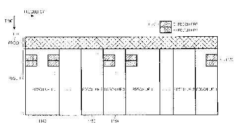
transmission was received by the Node B.
[10] The Node B separately codes and transmits each DCI format through a
PDCCH.
[11] FIG. 2 is a block diagram illustrating a conventional processing chain
for
transmitting a DCI format.
[12] Referring to FIG. 2, the Medium Access Control (MAC) layer IDentity of
the UE (or
UE ID), for which a DCI format is intended, masks the Cyclic Redundancy Check
(CRC) of the DCI format codeword in order to enable the reference UE to
identify that
the particular DCI format is intended for the reference UE. The CRC 220 of the
(non-coded) DCI format bits 210 is computed and is subsequently masked 230
using
the eXclusive OR (XOR) operation between CRC bits and the UE ID 240, i.e.,
X0R(0,0) = 0, X0R(0,1) = 1, X0R(1,0) = 1, and X0R(1,1) = O.
[13] The masked CRC is then appended to the DCI format bits 250, channel
coding 260 is
performed, for example, using a convolutional code, followed by rate matching
270 to
CA 02881659 2015-02-12
3
WO 2011/037439 PCT/ICR2010/006597
the allocated PDCCH resources, and then interleaving and modulation 280.
Thereafter,
a control signal 290 is transmitted.
[14] A UE receiver performs the reverse operations of the Node B
transmitter to
determine whether a DCI format in the PDCCH was intended for the UE.
[15] FIG. 3 is a block diagram illustrating a conventional processing chain
for receiving a
DCI format.
[16] Referring to FIG. 3, a received control signal, i.e., a PDCCH, 310 is
demodulated
and the resulting bits are de-interleaved 320. Rate matching applied in the
Node B
transmitter is restored 330, and the output is subsequently decoded 340. After
decoding, the DCI format bits 360 are obtained, after extracting the CRC bits
350,
which are then de-masked 370 by applying the XOR operation with the UE ID 380.
Thereafter, the UE performs a CRC test 390. If the CRC test passes, the UE
considers
the DCI format as being valid and determines the parameters for PDSCH
reception
(DL DCI format) or PUSCH transmission (UL DCI format). If the CRC test does
not
pass, the UE disregards the DCI format.
[17] The information bits of the DCI format correspond to several
Information Elements
(IEs) such as, for example, the Resource Allocation (RA) IE indicating the
part of the
operating BandWidth (BW) allocated to a UE for PDSCH reception or PUSCH
transmission, the Modulation and Coding Scheme (MCS) IE, the IE related to the
HARQ operation, etc. The BW unit for PDSCH or PUSCH transmissions is assumed
to consist of several REs, e.g., 12 REs, and will be referred to as a Physical
Resource
Block (PRB).
[18] PDCCHs for a UE are not transmitted at fixed and predetermined
locations and do
not have predetermined coding rate. Consequently, a UE performs multiple PDCCH
decoding operations in each sub-frame to determine whether any of the PDCCHs
transmitted by the Node B is intended for the UE. In order to assist UEs with
the
multiple PDCCH decoding operations, the PDCCH REs are grouped into Control
Channel Elements (CCEs) in the logical domain. For a given number of DCI
format
bits as illustrated in FIG. 2, the number of CCEs for the respective PDCCH
transmission depends on the channel coding rate. For UEs experiencing low or
high
Signal-to-Interference and Noise Ratio (SINR) in the DL, the Node B may
respectively
use a low or high channel coding rate in order to achieve a desired PDCCH
BLock
Error Rate (BLER). Therefore, a PDCCH transmission to a UE experiencing low DL
SINR typically requires more CCEs that a PDCCH transmission to a UE
experiencing
high DL SINR. Alternatively, different power boosting of CCE REs may also be
used
in order to achieve a target BLER. Typical CCE aggregation levels for PDCCH
trans-
missions are assumed to follow a "tree-based" structure, for example, 1, 2, 4,
and 8
CCEs.
CA 02881659 2015-02-12
4
WO 2011/037439 PCT/1CR2010/006597
[19] For the PDCCH decoding process, a UE may determine a search space for
a
candidate PDCCH, after it restores the CCEs in the logical domain, according
to a
common set of CCEs for all UEs in a UE-Common Search Space (UE-CSS) and
according to a UE-specific set of CCEs in a UE-Dedicated Search Space (UE-
DSS).
The UE-CSS includes the first C CCEs in the logical domain. The UE-DSS may be
de-
termined according to a pseudo-random function having UE-common parameters as
inputs, such as the sub-frame number or the total number of PDCCH CCEs in the
sub-
frame, and UE-specific parameters such as the identity assigned to a UE
(UE_ID).
[20] For example, for CCE aggregation levels LE { 1, 2, 4, 81, the CCEs
corresponding to
PDCCH candidate m can be given by Equation (1).
[21]
L {(Yk + m) mod LNccE,k / + = (1)
[22] In Equaton (1), NCCE,k is a total number of CCEs in sub-frame k, i=1,
..., L-1,
m=0,...,M(L)-1, and M(L)is a number of PDCCH candidates for the respective CCE
ag-
gregation levels. Exemplary values of MU-) for LE{ 1, 2, 4, 8} are,
respectively, {6, 6, 2,
21. For the UE-CSS, Yk=0. For the UE-DSS, Yk=(A=Yk_i) mod D where, for
example,
Y_I=UE_ID#0, A=39827 and D=65537.
[23] DCI formats conveying information to multiple UEs, such as DCI format
3 or DCI
format 1C, are transmitted in the UE-CSS. If enough CCEs remain after
transmitting
DCI formats 3 and 1C, the UE-CSS may also convey some DCI formats for PDSCH
receptions or PUSCH transmissions by UEs. The UE-DSS exclusively conveys DCI
formats for PDSCH receptions or PUSCH transmissions. In an exemplary setup,
the
UE-CSS includes 16 CCEs and supports 2 PDCCH with CCEs, or 4 PDCCH with
CCEs, or 1 PDCCH with CCEs and 2 PDCCH with CCEs. The CCEs for the UE-CSS
are placed first in the logical domain (prior to interleaving).
[24] FIG. 4 illustrates a conventional PDCCH transmission process. After
channel coding
and rate matching, as illustrated in FIG. 2, the encoded DCI format bits are
mapped to
CCEs in the logical domain.
[25] Referring to FIG. 4, the first 4 CCEs (L=4), CCE1 401, CCE2 402, CCE3
403, and
CCE4 404 are used for DCI format transmission to UEl. The next 2 CCEs (L=2),
CCE5 411 and CCE6 412, are used for DCI format transmission to UE2. The next 2
CCEs (L=2), CCE7 421 and CCE8 422, are used for DCI format transmission to
UE3.
The last CCE (L=1), CCE9 431, is used for DCI format transmission to UE4.
[26] The DCI format bits may be scrambled 440 using a binary scrambling
code, which is
typically cell-specific, and are subsequently modulated 450. Each CCE is
further
divided into mini-CCEs. For example, a CCE including 36 REs can be divided
into 9
mini-CCEs, each having 4 REs.
[27] Interleaving 460 is applied among mini-CCEs (blocks of 4 QPSK
symbols). For
CA 02881659 2015-02-12
WO 2011/037439 PCT/ICR2010/006597
example, a block interleaver may be used where the interleaving is performed
on
symbol-quadruplets (4 Quadrature Phase Shift Keying (QPSK) symbols
corresponding
to the 4 REs of a mini-CCE) instead of on individual bits. After interleaving
the mini-
CCEs, the resulting series of QPSK symbols may be shifted by J symbols 470,
and
then each QPSK symbol is mapped to an RE 480 in the PDCCH region of the DL sub-
frame. Therefore, in addition to the RS from the Node B transmitter antennas,
491 and
492, and other control channels such as the PCFICH 493 and the PHICH (not
shown),
the REs in the PDCCH include QPSK symbols corresponding to DCI format for UE1
494, UE2 495, UE3 496, and UE4 497.
[281 In order to support higher data rates and signal transmission in BWs
larger than the
BWs of individual carriers (or cells) supporting legacy communications,
aggregation
of multiple carriers (or cells) can be used. For example, to support
communication over
100 MHz, aggregation of five 20 MHz carriers (or cells) can be used. For ease
of de-
scription, UEs that can only operate over a single carrier (or cell) will be
refeiTed to
herein as Legacy-UEs (L-UEs) while UEs that can operate over multiple carriers
(or
cells) will be referred to herein as Advanced-UEs (A-UEs).
[29] FIG. 5 illustrates a principle of carrier aggregation. An operating BW
of 100 MHz
includes the aggregation of 5 (contiguous, for simplicity) carriers, 521, 522,
523, 524,
and 525, each having a BW of 20 MHz. Similarly to the sub-frame structure for
com-
munication over a single carrier in FIG. 1, the sub-frame structure for
communication
over multiple carriers includes a PDCCH region, for example, 531 through 535,
and a
PDSCH region, for example, 541 and 545.
[30] FIG. 6 is a diagram illustrating a conventional heterogeneous network
deployment.
[31] Referring to FIG. 6, an area covered by a macro-Node B 610 encompasses
areas
covered by micro-Node Bs 620 and 630. Because the macro-Node B covers a larger
area than a micro-Node B, its transmission power is substantially larger than
the
transmission power of a micro-Node B. Consequently, for topologies such as il-
lustrated in FIG. 6, the signals transmitted by a macro-Node B can cause
severe in-
terference to the signals transmitted by a micro-Node B. Interference
coordination
techniques can be applied to PDSCH transmissions to mitigate macro-to-micro in-
terference using different PRBs between PDSCH signal transmissions from the
macro-
Node B and a micro-Node B. However, such interference coordination is not
possible
for the PDCCH because the CCEs are pseudo-randomly distributed over the entire
operating BW, as was previously described.
[32] To avoid interference to PDCCH transmissions in a micro-cell, all
PDCCH trans-
missions can be in the macro-cell and a Carrier Indicator, or Cell Indicator,
(CI) IE can
be introduced in the DCI formats to indicate whether the DCI format is for the
macro-
cell or for the micro-cell. For example, a CI TE of 2 bits can indicate
whether the DCI
CA 02881659 2015-02-12
6
WO 2011/037439 PCT/ICR2010/006597
format is for the macro-cell or for any of a maximum of three micro-cells.
[33] In addition to providing PDCCH interference avoidance, PDCCH
transmission in
certain cells may be avoided for practical reasons. For example, it is
desirable to avoid
PDCCH transmissions in cells with small BW as they are inefficient and lead to
large
respective overhead. Also, PDSCH transmissions in a cell can be optimized to
occur
over all DL sub-frame symbols if transmissions of PDCCH and of other
supporting
signals such as UE-common RS, are avoided.
[34] The CI functionality can accommodate:
[35] PUSCH scheduling in the UL of multiple cells through PDCCH
transmission in a
single cell;
[36] PDSCH scheduling in the DL of multiple cells through PDCCH
transmission in a
single cell; and
[37] PDCCH transmission in a first cell (macro-cell) and in a second cell
(micro-cell).
[38] FIG. 7 is a diagram illustrating a conventional PUSCH scheduling in
the UL of
multiple cells through PDCCH transmission in a single cell.
[39] Referring to FIG. 7, a PDCCH in a single cell 710 is associated with
the UL of two
cells, 720 and 730. Consequently, PDCCHs scheduling PUSCH transmissions from
Cell 1 and Cell 2 are transmitted in a single cell and the cell of PUSCH
transmission
can be identified by a CI IE consisting of 1 bit.
[40] FIG. 8 is a diagram illustrating a conventional PDSCH scheduling in a
DL of
multiple cells through PDCCH transmission in a single cell.
[41] Referring to FIG. 8, only Cell 1 810 and Ce113 830 transmit PDCCH.
Scheduling for
Ce112 820 is performed through PDCCH transmission in Cell 1 and scheduling for
Ce114 840 and Ce115 850 is performed through PDCCH transmissions in Ce113.
[42] FIG. 9 is a diagram illustrating a conventional PDCCH transmission in
a first cell
(macro-cell) and in a second cell (micro-cell), which may occur to avoid
interference
in PDCCH transmissions between a macro-cell and a micro-cell.
[43] Referring to FIG. 9, although both macro-cell and micro-cell may have
PDSCH
transmissions in Celli 910 and Ce112 920, the macro-cell transmits PDCCH only
in
Cell 1 and the micro-cell transmit PDCCH only in Ce112.
[44] One issue for supporting PDCCH transmissions using a CI is the PDCCH
size. In
communication systems having a single cell, the PDCCH is assumed to be limited
to a
maximum number of M OFDM symbols. In communication systems having multiple
cells and having PDCCH transmission in a single cell, this limitation of the
PDCCH
size may cause scheduling restrictions. In general, the PDCCH size may need to
be
increased if the PDCCH in one cell performs scheduling in multiple cells.
[45] For the UE-CSS, which is assumed to include a fixed number of CCEs, it
may not be
possible to transmit additional PDCCH corresponding to additional cells.
CA 02881659 2015-02-12
7
WO 2011/037439 PCT/1CR2010/006597
[46] For the UE-DSS, modification and expansion is needed in order to
transmit multiple
DCI formats to a UE in the PDCCH region of a single cell.
[47] For the blind decoding operations a UE needs to perform, their number
may scale
linearly with the number of cells for which PDCCH is transmitted in a single
cell. It is
desirable to avoid such an increase in order to avoid the associated impact on
the UE
receiver complexity.
[48] Therefore, there is a need to expand the PDCCH region in a single cell
to support
PDCCH transmissions for scheduling in multiple cells.
[49] There is a further need to expand the UE-CSS in a single cell to
enable PDCCH
transmission conveying UE-common information for multiple cells.
[50] There is another need to expand the capacity of the UE-DSS in a single
cell for
scheduling over multiple cells.
[51] Additionally, there is another need to reduce the number of blind
decoding op-
erations a UE needs to perform.
Disclosure of Invention
Technical Problem
[52] Accordingly, the present invention has been designed to solve at least
the afore-
mentioned limitations and problems in the prior art and to provide the
following ad-
vantages. An aspect of the present invention is to provide methods and
apparatus for
expanding a control region in a single cell from supporting transmission of
DCI to a
UE for communication over the single cell to supporting transmission of DCI to
the
UE for communication over multiple cells.
Solution to Problem
[53] In accordance with an aspect of the present invention, a conventional
control region
in a single cell, including a UE-CSS and a UE-DSS and supporting DCI
transmission
for the single cell, is expanded to support DCI transmission for multiple
cells by
including either multiple UE-CSS, each multiple UE-CSS corresponding to each
of the
multiple cells, or multiple UE-DSS, each multiple UE-DSS corresponding to each
of
the multiple cells, or both.
[54] In accordance with another aspect of the present invention, support of
DCI
transmission for multiple cells, each having a Cell Identity (Ce11_ID),
through a control
region in a single cell is provided by informing the UE of the Cell_ID for
each of the
multiple cells and then defining a distinct UE-DSS for each of the multiple
cells in the
control region of the single cell, where each distinct UE-DSS has the same
structure 'as
the UE-DSS for DCI transmission over only the single cell and its location
additionally
depends only on the respective Cell_ID. The DCI is conveyed through DCI
formats
and DCI formats in each UE-DSS may include a CI IE that is derived from the
CA 02881659 2016-05-13
75998-189D1
8
Cell_ID.
[55] In accordance with another aspect of the present invention,
support of DCI
transmission for multiple cells through a control region in a primary cell is
provided by
defining a first control region for DCI transmission corresponding to a first
set of cells that
includes the primary cell, and a second control region for DCI transmission
corresponding to a
second set of cells including the multiple cells that are not in the first set
of cells. The first
control region includes the same resources as the control region for DCI
transmission only in
the primary cell. The second control region includes resources that would
otherwise be used
for data transmission in the primary cell.
[55a] According to one aspect of the present invention, there is provided a
method
for receipt of downlink control information (DCI) in a communication system,
the method
comprising the steps of: receiving information representative of presence of
carrier indicator
on higher layer signaling from a Node B; receiving information representative
of at least one
cell index on higher layer signaling from the Node B; defining a UE specific
search space
based on an aggregation level, a UE ID, and at least one carrier indicator
value, where the UE
specific search space comprises a set of physical downlink control channel
(PDCCH)
candidates based on the aggregation level; and decoding at least one PDCCH
including at
least one DCI respectively based on the UE ID; wherein the at least one
carrier indicator value
is based on the at least one cell index.
[55b] According to another aspect of the present invention, there is
provided an
apparatus for receipt of downlink control information (DCI) in a communication
system, the
apparatus comprising: a receiver configured to receive information
representative of presence
of carrier indicator on higher layer signaling from a Node B, and to receive
information
representative of at least one cell index on higher layer signaling from the
Node B; and a
controller configured to define a UE specific search space based on an
aggregation level, a
UE ID, and at least one carrier indicator value, where the UE specific search
space comprises
a set of physical downlink control channel (PDCCH) candidates based on the
aggregation
level, and to decode at least one PDCCH including at least one DCI
respectively based on the
CA 02881659 2016-05-13
75998-189D1
8a
UE ID; wherein the at least one carrier indicator value is based on the at
least one cell index.
[55c] According to still another aspect of the present invention, there is
provided a
method for transmission of downlink control information (DCI) in a
communication system, the
method comprising the steps of: transmitting information representative of
presence of carrier
indicator on higher layer signaling to a user equipment (UE); and transmitting
information
representative of at least one cell index on higher layer signaling to the UE;
wherein a UE specific
search space is defined based on an aggregation level, a UE ID, and at least
one carrier indicator
value, where the UE specific search space comprises a set of physical downlink
control channel
(PDCCH) candidates based on the aggregation level; and wherein at least one
PDCCH comprises
at least one DCI respectively based on the UE ID; and wherein the at least one
carrier indicator
value is based on the at least one cell index.
[55d] According to yet another aspect of the present invention, there is
provided an
apparatus for transmission of downlink control information (DCI) in a
communication system, the
apparatus comprising: a transmitter configured to transmit information
representative of presence
of carrier indicator on higher layer signaling to a user equipment (UE), and
to transmit
information representative of at least one cell index on higher layer
signaling to the UE; and a
controller configured to control the transmitter to transmit, to the UE, at
least one DCI to the UE
within a UE specific search space is defined based on an aggregation level, a
UE ID, and at least
one carrier indicator value, where the UE specific search space comprises a
set of physical
downlink control channel (PDCCH) candidates based on the aggregation level;
and wherein at
least one PDCCH comprises the at least one DCI respectively based on the UE
ID; and wherein
the at least one carrier indicator value is based on the at least one cell
index.
Advantageous Effects of Invention
[56] As described above, exemplary embodiments of the present
invention provide
methods and apparatus for expanding a control region in a single cell from
supporting
transmission of DCI to a UE for communication over the single cell to
supporting transmission of
DCI to the UE for communication over multiple cells.
CA 02881659 2015-02-12
75998-189D1
8b
Brief Description of Drawings
[571 The above and other aspects, features, and advantages of the
present invention will
be more apparent from the following detailed description taken in conjunction
with the
accompanying drawings, in which:
[58] FIG. 1 is a diagram illustrating a conventional structure for PDCCH
transmission;
[59] FIG. 2 is a block diagram illustrating a conventional processing chain
for
transmitting a DCI format;
[60] FIG. 3 is a block diagram illustrating a conventional processing chain
for receiving a
DCI format;
[61] FIG. 4 is a diagram illustrating a conventional PDCCH transmission
process;
[62] FIG. 5 is a diagram illustrating a principle of carrier aggregation;
[63] FIG. 6 is a diagram illustrating a conventional heterogeneous network
deployment;
[64] FIG. 7 is a diagram illustrating a conventional PUSCH scheduling in a
UL of
multiple cells through PDCCH transmission in a single cell;
[65] FIG. 8 is a diagram illustrating a conventional PDSCH scheduling in a
DL of
multiple cells through PDCCH transmission in a single cell;
[66] FIG. 9 is a diagram illustrating a conventional PDCCH transmission in
a first cell
= (macro-cell) and in a second cell (micro-cell);
[67] FIG. 10 is a diagram illustrating a method of informing an A-UE
whether a CI IE is
included in DCI formats in a UE-specific manner, according to an embodiment of
the
present invention;
[68] FIG. 11 is a diagram illustrating an E-PDCCH multiplexing structure
where A-UEs
assume a maximum PDCCH size to determine a first E-PDCCH symbol, according to
CA 02881659 2015-02-12
9
WO 2011/037439
PCT/1CR2010/006597
=
an embodiment of the present invention;
[69] FIG. 12 is a diagram illustrating an E-PDCCH multiplexing structure
where A-UEs
decode a PCFICH to determine an actual PDCCH size and a first E-PDCCH symbol,
according to an embodiment of the present invention;
[70] FIG. 13 is a diagram illustrating an assignment of different CI values
to different
cells, according to an embodiment of the present invention;
[71] FIG. 14 is a diagram illustrating placement of CCEs for multiple UE-
CSS, according
to an embodiment of the present invention;
[72] FIG. 15 is a diagram illustrating an operation for generating a
distinct UE-DSS for
each cell through a respective distinct initialization of a variable
determining the
location of a UE-DSS, according to an embodiment of the present invention;
[73] FIG. 16 is a diagram illustrating an extension of a PDCCH size by
configuring a set
of possible values and using a PCFICH to indicate one value in the set,
according to an
embodiment of the present invention; and
[74] FIG. 17 is a diagram illustrating a combination of explicit and
implicit indication by
a Node B of a UE-CSS size, according to an embodiment of the present
invention.
Mode for the Invention
[75] Various embodiments of the present invention will now be described in
detail with
reference to the accompanying drawings. This invention may, however, be
embodied
in many different forms and should not be construed as limited to the
embodiments set
forth herein. Rather, these embodiments are provided so that this disclosure
will be
thorough and complete and will fully convey the scope of the invention to
those skilled
in the art.
[76] Additionally, although the present invention is described in relation
to an Orthogonal
Frequency Division Multiple Access (OFDMA) communication system, it also
applies
to Frequency Division Multiplexing (FDM) systems and to Single-Carrier
Frequency
Division Multiple Access (SC-FDMA), OFDM, FDMA, Discrete Fourier Transform
(DFT)-spread OFDM, DFT-spread OFDMA, SC?OFDMA, and SC-OFDM.
[77] In accordance with an embodiment of the present invention, an A-UE is
semi-
statically configured, for example, through Radio Resource Control (RRC)
signaling,
the cells over which it may have PDSCH reception or PUSCH transmission. A link
between the DL and the UL in those cells may also be configured. The inclusion
of the
CI IE in DCI formats can be either UE-specific or cell-specific. When the CI
IE in DCI
formats is UE-specific, each A-UE is informed through higher layer signaling
(MAC
or RRC signaling) whether its assigned DCI formats in a cell include a CI IE.
When
the CI IE in DCI formats is cell-specific, the Node B may broadcast whether a
CI IE is
included in the DCI formats. In both cases, the values of the CI to be
monitored by an
CA 02881659 2015-02-12
WO 2011/037439 PCT/ICR2010/006597
A-UE are also included. The DCI formats having the CI IE may be all DCI
formats or
a predetermined subset of DCI formats. For example, DCI formats in the UE-CSS
may
not contain CI while DCI formats in the UE-DSS may contain CI.
[78] FIG. 10 is a diagram illustrating a method of informing an A-UE
whether a CI 1E is
included in DCI formats in a UE-specific manner, according to an embodiment of
the
present invention.
[79] Referring to FIG. 10, an A-UE is configured in the DL of Cell] 1010,
Ce112 1020,
and Ce113 1030 for PDSCH reception and in the UL of Cell 1 1040 and Ce112 1050
for
PUSCH transmission. The cells of PDCCH transmission are also informed to the A-
UE through higher layer signaling.
[80] In FIG. 10, a PDCCH is transmitted only in Cell 1 1060. For example,
the DL and UL
for Celli may correspond to a macro-cell, while the DL and UL of Ce112 may
correspond to a first micro-cell and the DL of Ce113, and the UL of Ce112 can
correspond to a second micro-cell. DCI formats associated with PUSCH
transmissions
or with TPC for PUSCH or PUCCH transmissions (DCI format 3) will be referred
to
as UL DCI formats. The remaining DCI formats are associated with PDSCH re-
ceptions and will be referred to as DL DCI formats.
[81] For the setup in FIG. 10, DL DCI formats to the UE include a CI IE
having 2 bits.
For example, for the DL, the CI values of '00', '01", and "10" can correspond
to Celli,
Ce112, and Ce113, respectively, while the CI value "11" is unused. Similarly,
for the
UL, the CI values of '0' and "1" can correspond to Celli and Ce112,
respectively. In
general, the number of bits for the CI IE can be different between DL DCI
formats and
UL DCI formats (including, for example, not having any CI IE bits in UL DCI
formats
while having CI IE bits in DL DCI formats). The association between CI values
and
Cells may also be implicitly determined. For example, ascending CI values of
"00",
"01", "10", and "11" can be mapped to Cells in order of increasing carrier
frequency.
[82] The use of CI to indicate the cell for which a DCI format is intended
may not be
necessary for cells with different BWs because the respective DCI formats may
have
different sizes. For example, for 2 cells, where the PDCCH is transmitted only
in one
cell, the CI inclusion in the DL DCI formats is not necessary if, for example,
one cell
has a BW of 20 MHz and the other cell has a BW of 5 MHz. In general, the
primary
reason for having a different DC1 format size for different BWs is the
Resource Al-
location (RA) IE in the DCI formats, which should have a larger size for cells
with
larger BWs, as it addresses a larger number of PRBs.
[83] The transmission of DCI formats to L-UEs is supported with the
conventional
PDCCH structure. The PDCCH transmission to A-UEs having PDSCH reception or
PUSCH transmission in the same cell is also supported with the conventional
PDCCH
structure. There is no differentiation between these A-UEs and the L-UEs with
respect
CA 02881659 2015-02-12
11
WO 2011/037439 PCT/KR2010/006597
to the PDCCH transmission, although different DCI formats may be used. For
ease of
reference, such A-UEs will be referred to as Primary-UEs (P-UEs) and the cell
with the
PDCCH transmission as Primary-cell (Pcell). Conversely, A-UEs having PDSCH
reception or PUSCH transmission in a cell other than the Pcell will be
referred to as
=
Secondary-UEs (S-UEs) and the corresponding cells as Secondary-cells (Scells).
[84] For example, in FIG. 10, UEs receiving PDSCH in Ce111 are P-UEs and
Cell 1 is the
Pce11, while UEs receiving PDSCH in Ce112 are S-UEs and Ce112 is a Scell. An A-
UE
can be both a P-UE and an S-UE depending on the cell (Pcell or Scell,
respectively).
Therefore, the classification of an A-UE as a P-UE or an S-UE is unique for
each cell
and may be different among cells as an A-UE can be a P-UE in the Pcell and the
S-UE
in an Scell.
[85] For the PDCCH transmission to S-UEs in Scells, the conventional PDCCH
structure
or a separate PDCCH structure may be used. For example, for lightly loaded
systems
for which the capacity (first M OFDM symbols of the DL sub-frame) of the con-
ventional PDCCH structure is not reached for scheduling P-UEs, it is also
possible to
support the transmission of DCI formats to S-UEs while, for heavily loaded
systems,
an additional PDCCH structure may be needed to support the PDCCH transmission
to
S-UEs.
[86] Whether the conventional PDCCH structure or an Extended PDCCH (E-
PDCCH)
structure is used can be predetermined or be informed by the Node B through
broadcast signaling or through UE-specific higher layer signaling. The PDCCH
CCEs
for an A-UE can be either in the PDCCH or in the E-PDCCH, but not in both.
Whether
an A-UE monitors the PDCCH or the E-PDCCH for scheduling a PDSCH or a PUSCH
in a specific cell can be semi-statically configured either through higher
layer signaling
or through broadcast signaling.
[87] If the E-PDCCH in the Pcell is used for scheduling a PDSCH or a PUSCH
in Scells,
the following is considered, in accordance with an embodiment of the present
invention:
[88] E-PDCCH Contents
[89] The E-PDCCH provides an extension to the PDCCH and therefore, conveys
in-
formation of the same nature. In addition to DCI formats for S-UEs, the E-
PDCCH
may include a respective PCFICH (referred to as an E-PCFICH) and a PHICH
(referred to as an E-PHICH) for PUSCH transmissions in Scells served by the E-
PDCCH. The E-PCFICH and the E-PHICH have the same structure as the PCFICH
and the PHICH, respectively.
[90] Frequency resources for E-PDCCH
[91] The DCI formats in the E-PDCCH are transmitted in CCEs, but the CCE
allocation is
in PRBs as the E-PDCCH is orthogonally multiplexed with the PDSCH. The PRBs
for
CA 02881659 2015-02-12
12
WO 2011/037439 PCT/KR2010/006597
the E-PDCCH can be semi-statically or dynamically configured. A semi-static
con-
figuration of E-PDCCH PRBs ensures adequate separation in the frequency domain
in
order to obtain frequency diversity or that the PRBs are selected according to
an in-
terference co-ordination technique minimizing interference from adjacent
cells.
[92] Time Resources for E-PDCCH
[93] The first E-PDCCH symbol can be the first OFDM symbol after the last
actual
PDCCH OFDM symbol or the first symbol after the last PDCCH OFDM symbol,
assuming the maximum number of PDCCH OFDM symbols. When the first E-PDCCH
symbol is the first OFDM symbol after the last actual PDCCH OFDM symbol, S-UEs
decode the PCFICH to determine the E-PDCCH start. When the first E-PDCCH
symbol is the first symbol after the last PDCCH OFDM symbol assuming the
maximum number of PDCCH OFDM symbols, maximum E-PDCCH decoding latency
results, but errors from incorrect PCFICH detection, which will lead in PDCCH
decoding failure, are avoided.
[94] The last E-PDCCH symbol can be statically, semi-statically, or
dynamically
configured. With static configuration, the last E-PDCCH symbol can be, for
example,
the seventh symbol of the DL sub-frame. With semi-static configuration, the
last E-
PDCCH symbol can be informed by the Node B through a broadcast channel. With
dynamic configuration, the last E-PDCCH symbol can be informed through the E-
PCFICH.
[95] The range of OFDM symbols indicated by the E-PCFICH for the E-PDCCH
can be
different than the range of OFDM symbols indicated by the PCFICH for the
PDCCH.
For example, the E-PCFICH may also indicate 0 OFDM symbols for the E-PDCCH in
which case the E-PCFICH and the E-PHICH may be transmitted in the PDCCH.
[96] FIG. 11 illustrates an E-PDCCH multiplexing structure where A-UEs
assume a
maximum PDCCH size to determine a first E-PDCCH symbol, according to an em-
bodiment of the present invention.
[97] Referring to FIG. 11, the PDCCH transmission 1110 has 2 OFDM symbols,
out of a
maximum of 3 PDCCH OFDM symbols. The first E-PDCCH symbol is the first
OFDM symbol after the PDCCH transmission, assuming the maximum of 3 OFDM
symbols. Therefore, the first E-PDCCH symbol is the fourth OFDM symbol of the
DL
sub-frame. The E-PCFICH transmission (not shown) is always in the first E-
PDCCH
symbol and, for the structure of FIG. 11, it indicates that the E-PDCCH is
transmitted
in 2 OFDM symbols 1120. The E-PDCCH transmission PRBs 1130 are semi-statically
configured through broadcast signaling by the Node B (for example, in an SIB).
The E-
PDCCH transmission is multiplexed with PDSCH transmissions to various UEs,
1140,
1150, and 1160. PDSCH transmissions to L-UEs may or may not occur in PRBs used
for E-PDCCH transmission. As an L-UE cannot be aware of the E-PDCCH existence,
CA 02881659 2015-02-12
13
WO 2011/037439 PCT/KR2010/006597
if it is assigned PDSCH reception in E-PDCCH PRBs, it will treat such PRBs as
PRBs
that include a PDSCH. Although this will degrade the PDSCH reception quality
for the
L-UEs, it is up to the Node B to determine whether or not perform such
scheduling. A-
UEs can be aware of the E-PDCCH PRBs and apply the appropriate rate matching
for
their respective PDSCH receptions.
[98] FIG. 12 illustrates an E-PDCCH multiplexing structure where A-UEs
decode a
PCFICH to determine an actual PDCCH size and a first E-PDCCH symbol, according
to an embodiment of the present invention.
[99] Referring to FIG. 12, a PDCCH transmission 1210 has 2 OFDM symbols.
The first
E-PDCCH symbol is the third OFDM symbol, which is the first OFDM symbol after
the PDCCH transmission. The E-PCFICH transmission (not shown) is always in the
first E-PDCCH symbol and, in the structure illustrated in FIG. 12, it
indicates that the
E-PDCCH is transmitted in 2 OFDM symbols 1220. The E-PDCCH transmission
PRBs 1230 are predetermined.
[100] If the transmission of DCI formats for multiple Scells is conveyed
through the E-
PDCCH, in accordance with an embodiment of the present invention, all E-PDCCH
CCEs are jointly considered for all Scells, instead of having a separate set
of CCEs for
each Scell. Therefore, there is only a single set of CCEs in the E-PDCCH,
where each
S-UE may have its UE-CSS and its UE-DSS. This also enables the transmission of
a
single E-PCFICH, instead of multiple E-PCFICH with each one corresponding to a
different Scell in the E-PDCCH.
[101] UE-CSS
[102] In a first alternative, the UE-CSS for S-UEs is separately configured
and its size, in
number of CCEs, may be broadcasted by the Node B. For example, the UE-CSS size
may take one of four predetermined values and the Node B broadcasts 2 bits to
indicate that value (for example, through an SIB in the Pcell) or to indicate
that the
UE-CSS size is either 1, 2, 3, or 4 times a basic size of K CCEs. The CCEs for
the UE-
CSS in the E-PDCCH are placed first, i.e., before the CCEs for the UE-DSS.
Once an
S-UE is informed of the UE-CSS size, it needs to determine the CCEs
corresponding
to each Scell.
[1031 In a first option for the first alternative, the S-UE is informed of
the order of Scells
either through higher layer signaling, for UE-specific CI configuration, or as
part of the
system information for cell-specific CI configuration. This is equivalent to
an S-UE
being informed of the CI value for its DCI formats. In case a CI may not
exist, such as,
for example, when the cells have unequal BWs, the order may be in terms of de-
creasing BWs, e.g., the larger BWs are ordered first.
[104] FIG. 13 is a diagram illustrating an assignment of different CI
values to different
cells, according to an embodiment of the present invention.
CA 02881659 2015-02-12
14
WO 2011/037439 PCT/1CR2010/006597
[1051 Referring to FIG. 13, the CCEs for the UE-CSS of the macro-cell 1310
are placed in
the PDCCH. The CCEs for the UE-CSS for micro-cell 1 1320 are ordered first in
the
E-PDCCH (CI = 1) and the CCEs for the UE-CSS for micro-cell 2 1330 are ordered
second in the E-PDCCH (CI = 2). Once the CI values have been assigned to
Scells, the
CCEs of the UE-CSS of S-UEs are placed in the same order in the logical
domain.
[106] FIG. 14 is a diagram illustrating placement of CCEs for multiple UE-
CSS, according
to an embodiment of the present invention.
[107] Referring to FIG. 14, the Ll CCEs for a first UE-CSS of S-UEs (micro-
cell 1 or for a
first set of S-UEs, CI = 1) are placed first 1410, followed by the L2 CCEs for
a second
UE-CSS of S-UEs (micro-cell 2 or for a second set of S-UEs, CI = 2) 1420. The
placement of the CCEs for the UE-DSS 1430 occurs after the placement of the
CCEs
for the UE-CSS in the logical domain. The number of CCEs of the UE-CSS for S-
UEs
for the different CI values, denoted by Ll and L2 in FIG. 14, may be
implicitly de-
termined from the total UE-CSS size or may be informed by the Node B through
broadcast signaling. Alternatively, the number of CCEs for the UE-CSS of S-UEs
can
be the same for all CI values, regardless of the DL or UL operating BW in each
Scell
(that is, L1 = L2 in FIG. 14).
[108] The CCEs for the UE-CSS of S-UEs are ordered as illustrated in FIG.
14 to reduce
the associated number of Blind Decoding Operations (BD0s) because, for each UE-
CSS, an S-UE searches a sub-set of the total set of CCEs allocated to the
total UE-
CSS. Moreover, by ordering the UE-CSSs for S-UEs, it is not necessary to
include the
CI IE in DCI formats transmitted in each UE-CSS.
[109] In a second option for the first alternative, the ordering of
individual UE-CSS for S-
UEs is not applied and the respective CCEs may be distributed over the entire
set of
CCEs for the total UE-CSS. Thereafter, CI inclusion in the DCI formats is
performed
and the UE search process for DCI formats can be performed for the UE-DSS of S-
UEs as will be described below.
[110] In a second alternative, the UE-CSS remains unchanged, the S-UEs are
treated as P-
UEs with respect to the transmission of DCI format 3 and DC' format 1C in
Scells, and
there is no differentiation of UEs into different categories with respect to
the UE-CSS.
[111] The PCH can be transmitted to all S-UEs in the cell with the PDCCH
transmission
(Pcell).
[112] Assuming no transmission of synchronization signals from cells (such
as micro-cells)
without PDCCH transmission (Scells), S-UEs acquire the synchronization signal
of the
cell (such as a macro-cell) with PDCCH transmission (Pcell). Thereafter, the
RACH
process is completed through the Pcell and no additional RACH response
signaling,
corresponding to cells without PDCCH transmission (Scells), is necessary.
[113] The SIBs for cells (such as micro-cells) without PDCCH transmission
(Scells) can
CA 02881659 2015-02-12
WO 2011/037439 PCT/KR2010/006597
also be transmitted from the cell (such as macro-cell) with PDCCH transmission
(Pcell) using different CRC masks in DCI format 1C to indicate the cell
corresponding
to the SIB transmission.
[114] DCI format 3 multiplexes TPC commands corresponding to UEs in the
cell (such as
a macro-cell) with PDCCH transmission (Pcell) and to UEs in the cells (such as
micro-
cells) without PDCCH transmission (Scells).
[115] Accordingly, P-UEs have their UE-CSS for DCI format transmission in
the PDCCH
as in a backward compatible system including a single cell. For S-UEs, either
a new
UE-CSS is defined in the E-PDCCH, as described above in the first alternative,
or no
additional UE-CSS is defined and all UEs (P-UEs and S-UEs) use the same UE-CSS
in
the PDCCH, as described above in the second alternative.
[116] UE-DSS
[117] For the UE-DSS and single-cell operation, using the previously
defined notation, the
CCEs corresponding to a PDCCH candidate m are given by Equation (2).
[118] ... (2)
=LSk = frk + m)modlyCCE L .1) + i
A
[119] In Equation (2), NCCE,k is the total number of CCEs in sub-frame k,
m=0,...M(L)-1, and M(L) is the number of candidates in the UE-DSS.
[120] The above UE-DSS structure leads to identical UE-DSSs for different
cells (Pcell or
Scells) as they are assumed to share the same UE-DSS in the E-PDCCH (or in the
PDCCH when it supports the transmission of DCI formats for multiple cells).
[121] In order to provide distinct UE-DSS, in addition to the UE_ID, in
accordance with an
embodiment of the present invention, the UE-DSS also depends on the Cell_ID.
This
can substantially decrease the probability that a DCI format transmission is
blocked
due to the unavailability of CCEs in the UE-DSS. Reducing this blocking
probability
increases the probability that a PDSCH or PUSCH scheduling occurs and
therefore,
improves the respective DL or UL system throughput and enhances operating
quality
and reliability.
[122] The Cell_ID may be the CI value allocated to each cell. For example,
the UE may be
inforined of the Cell_ID through higher layer signaling. At least when the
cells have
equal BWs (and a respective CI is defined), the Cell_ID may be the same as the
re-
spective CI. The UE may obtain the Cell_ID during initial synchronization with
the re-
spective cell, or if the cell does not transmit synchronization signals, the
UE may
obtain the respective Cell_ID through higher layer signaling from the cell
transmitting
synchronization signals after synchronization. Additionally, the Cell_ID may
be UE-
specific and informed to each UE through higher layer signaling. For example,
for 3
cells, instead of having three different respective Cell_IDs, the Cell_ID for
each UE
can depend on the number of cells the UE is configured for. If UE1 is
configured for
CA 02881659 2015-02-12
16
WO 2011/037439 PCT/ICR2010/006597
Cell 1 and Ce112, the respective Cell_IDs can be Cell_ID1 and Cell_ID2. If UE2
is
configured for Ce112 and Ce113, the respective Cell_IDs can also be Cell_ID1
and
[123] The following example further demonstrates the occurrence of
transmission blocking
for a DCI format. Assuming that DCI formats to a UE are transmitted with 4
CCEs,
then, as there are only 2 candidates in the UE-DSS for this CCE aggregation
level,
transmission of DCI formats for at most 2 cells can be supported (or one cell,
for both
PDSCH reception and PUSCH transmission). Also, due to randomization through in-
terleaving, the UE-DSSs for different UEs may have overlapping CCEs, and for
this
reason it will often be likely that the transmission of a DCI format for only
a single cell
can be supported.
[124] An embodiment of the invention to construct separate UE-DSS for each
cell
considers that the initialization of the variable Yk includes the Cell_ID.
When 0$0=0,
00.1=1, 1$0=1, 10.1=0, where e denotes the binary modulo add operation, an A-
UE
receives multiple PDSCH or transmits multiple PUSCH in multiple cells while
the re-
spective DCI formats are transmitted in a single cell, and Y_1 =
(UE_ID)0(Cell_ID)*()
for the UE-DSS of the respective cell.
[125] FIG. 15 illustrates an initialization of a variable Yk with a Cell_ID
according to an
embodiment of the present invention.
[126] Referring to FIG. 15, the binary UE_ID 1510 and the binary Cell_ID
1520 are added
by a binary adder 1530 to provide the initial value Yk.i 1540 of the variable
Yk, ran-
domizing the CCEs in the UE-DSS in sub-frame k for DCI formats corresponding
to
the respective cell. Assuming a 16-bit UE ID, the requirement Y_1#0 prevents
the use
of a small number of UE_IDs, which has only a minor impact on the total number
of 2
16=65536 available UE Ids, considering that the total number of cells for
which the DCI
formats are transmitted in a single cell is less than 10. Also, as the
variable Yk depends
on the Cell_ID, it should be denoted as Ykc with c=0,1,...,N,-1, where N. is
the number
of cells for which the respective DCI formats are conveyed in a single cell
(Pcell).
[127] In another embodiment of the invention to construct separate UE-DSS
for each cell,
denoting as f(c) a function of the CI or of the Cell_ID for cell c, each UE-
DSS can be
obtained by Equation (3).
[128](3)
4') = L = + m + f (c))1modly
,c CCE ,k 11` i
[129] One condition for (L) may be that the UE-DSS corresponding to
PDSCH/
ke
PUSCH scheduling in the Pcell should be defined as for L-UEs. This is useful
for
maintaining the legacy operation when all cells, other than the Pcell, are
deactivated.
CA 02881659 2015-02-12
17
WO 2011/037439
PCT/KR2010/006597
Therefore, if cp is the CI or Cell_ID for the Pcell, then f(cp)=0.
[130] For CI or Cell_ID values c other than cp, f(c) may be determined as
f(c)=1,2,...,7
(assuming a 3-bit CI), which can be ranked in ascending order based on the
assigned
CI values. Only active cells are considered in order to reduce the self-
blocking
probability for the UE-DSS of an A-UE. The exact values for Scells (excluding
the
Pcell) are not material as long as they are consecutive and the condition
f(c)=0 is
satisfied for the Pcell. For example, for CI or Cell_ID values c other than
cp, the
function f(c) may be determined as f(c)=-3,-2,-1,1,2,3, or in general, by
alternating as-
signments of positive and negative integer values in a consecutive manner
around ficp
)=0 (starting from 1, and continuing with -1, 2, -2, and so on).
[131] The transmission of DCI formats for scheduling in multiple Scells
increases the
number of BDOs an A-UE performs. Without any restrictions in the locations of
these
possible DCI formats, this increase in the number of BDOs is linear with the
number of
Scells. This increases the UE receiver complexity and also increases the
probability of
a false CRC test (resulting to a UE incorrectly considering a DCI format as
intended
for it).
[132] Several alternative designs exist for reducing the number of BDOs.
All consider that
the possible locations of DCI formats in the multiple UE-DSSs for a reference
UE are
= mutually dependent. In addition to reducing the number of BDOs and CRC
tests, these
designs maintain the same receiver architecture (bank of decoders) for the
basic single-
cell UE-DSS decoding process regardless of the number of cells a UE is
configured.
[133] A first design uses the same aggregation level L for all DCI formats
to a reference
UE. If for the reference cell c1 a candidate m is identified by the UE in
position
L = kJ"' + m)modlyCCE IL j+ i , m = 0,- = = , M (14 -1, i = 0, = = = ,L -1
,k
an additional cell c, can have a potential candidate n in position
L = KY:2 + n)modly.CCE k IL _4+ i , n = 0, , M (L) ¨1
Therefore, after the UE identifies a DCI format for cell cl, it performs an
additional
BDOs (for n=0,...,M(L)-1) to determine if it also has one for cell c,.
[134] A second design enables different aggregation levels to be used for
the PDCCH, but
imposes a restriction in the possible candidates for each aggregation level.
If for cell cl
a PDCCH is identified for candidate m in position
m)modLN.,k
i m 0,¨ ,M (L) ¨1, = 0, , L1 ¨1,an ad-
ditional cell ci can have a potential PDCCH candidate in position
L2 = PP -I- in = MOd(rnin (Li , L2 ))MOCILNccE iL 2
j = 0, = = = , L2 ¨1
CA 02881659 2015-02-12
18
WO 2011/037439 PCT/1CR2010/006597
. Therefore, after the UE identifies a PDCCH for cell ci, it performs a number
ad-
ditional BDOs equal to the number of possible aggregation levels to determine
if it also
has a PDCCH for cell c,. In accordance with an embodiment of the present
invention,
this number of additional BDOs is 4, as the possible aggregation levels are
{1,2,4,8}.
This process can directly extend to additional cells.
[135] A third design is a combination of the first and second designs,
where the ag-
gregation level used for the PDCCH in a reference cell (Pce11) affects the
possible ag-
gregation levels for the PDCCH for the remaining cells (Sce11s) for which a UE
is
configured. For example, the aggregation levels used for the PDCCH for the
remaining
cells may only have the same or the next larger value relative to the one used
for the
PDCCH for the reference cell (if L=8 is used in the reference cell, then L=8
is also
used in the remaining cells). Additionally, the position of the PDCCH for the
reference
cell affects the possible PDCCH positions for the remaining cells. For
example, if the
PDCCH position for the reference cell is odd or even numbered, then the
position of
the potential PDCCH for the remaining cells is also odd or even numbered, re-
spectively. Therefore, for the third design, if for the cell cl a PDCCH is
identified for
candidate m in position , with
= M)M04NcrE i
L1 E
an additional cell c, can
e {1,2,4,8),m = 0, M (4) 1 i - 0
. = . , -
1 - , _ ,
have a potential PDCCH candidate in position
, 2L1) if L1
L, = 01":2 2n + mod(nt,2)))modly crs 1L2 j
<8, 1_2=LI if L1=8, n=0,...5m(L2)/2_15j=0,...,L2-1. This process can directly
extend to ad-
ditional cells.
{1361 Additional restrictions for the third design are possible, for
example, by requiring the
same CCE aggregation level to be used in all cells. The potential combinations
are
covered by combinations of the principles for the first and second designs as
described
by the third design.
[137] The previously described PDCCH extension was compatible with existing
single-cell
communications. However, PDCCH extension may also be supported in a non-
compatible manner. For this case, in accordance with an embodiment of the
present
invention, a different interpretation of the PCFICH values and a different
configuration
of the UE-CSS and UE-DSS may apply. Unlike legacy systems for which the PCFICH
conveys 3 predetermined values for the PDCCH size, such as for example 1, 2,
or 3
OFDM symbols, the PCFICH for non-compatible PDCCH extension can convey more
values, which are not predetermined but can semi-statically vary. The Node B
may
CA 02881659 2015-02-12
19
WO 2011/037439 PCT/1CR2010/006597
broadcast a configuration of PDCCH sizes, from a set of possible
configurations, and
the PCFICH may then simply indicate one size from the broadcasted
configuration of
PDCCH sizes. For example, the Node B may indicate one of the {1, 2, 3, 4}, {2,
3, 4,
5}, {3, 4, 5, 6} and {4, 5, 6, 7}, in number of OFDM symbols, for the PDCCH
size
configuration. The 2 bits in the PCFICH can then be used to inform the UEs of
the
PDCCH size within the configuration broadcasted by the Node B.
[138] FIG. 16 illustrates a PDCCH size extension by configuring a set of
possible values
and using a PCF1CH to indicate one value in the set, according to an
embodiment of
the present invention.
[139] Referring to FIG. 16, the Node B broadcasts 2 bits, for example,
"10", to indicate the
PDCCH size configuration of {3, 4, 5, 6} symbols 1610. The PDCCH size con-
figuration may take effect at a predetermined sub-frame after the Node B
broadcasts it,
such as, for example, in the first sub-frame S, such that modulo(S, 40) = 0.
The
PCFICH transmitted in each sub-frame indicates an element from the PDCCH size
configuration set, such as, for example, the third element 1620. The UE
determines the
PDCCH size based on both the broadcasted PDCCH size configuration and the
PCFICH value 1630.
[140] In addition to configuring a total PDCCH size, an individual size of
the UE-CSS or
UE-DSS can also be configured. For example, the Node B may broadcast the UE-
CSS
size. Consequently, A-UEs can know that the UE-CSS size may have one of four
pre-
determined values and the Node B simply broadcasts 2 bits to indicate that
value or to
indicate that the UE-CSS size is 1, 2, 3, or 4 times the basic UE-CSS size of
16 CCEs.
The indication of the UE-CSS size may also be implicit based on the PDCCH con-
figuration size. For example, if the Node B broadcasts the third PDCCH
configuration
size in FIG. 16, A-UEs can identify that the UE-CSS is 3 times the basic UE-
CSS size
of 16-CCEs, i.e., the UE-CSS size is 48 CCEs or it is determined by the third
element
in a configured set of UE-CSS sizes such as, for example, a set of {16, 28,
36, 44}
CCEs.
[141] FIG. 17 illustrates explicit and implicit indication by the Node B of
a UE-CSS size to
A-UEs, according to an embodiment of the present invention.
[142] Referring to FIG. 17, for explicit indication, the Node B informs A-
UEs of the UE-
CSS size through a broadcast channel, e.g., an SIB transmission. For example,
the
Node B transmits 2 bits with a value "10" to indicate 36 CCEs, which is the
third
element in a set of 4 possible UE-CSS sizes 1710. A-UEs, upon reception of
that
broadcast information, determine the UE-CSS for each cell 1720, as described
above,
for PDCCH extension compatible with legacy systems. For implicit indication,
the
Node B broadcasts the PDCCH size configuration (for example, in an SIB), as
described in FIG. 17, and based on this configuration, A-UEs determine the UE-
CSS
CA 02881659 2015-02-12
= 20 ,
WO 2011/037439 PCT/KR2010/006597
size and the UE-CSS for each cell. For example, the Node B may broadcast the
third
PDCCH size configuration 1730 and the then A-UEs determine the UE-CSS size to
be
36 CCEs 1740.
[143] While the present invention has been shown and described with
reference to certain
embodiments thereof, it will be understood by those skilled in the art that
various
changes in form and details may be made therein without departing from the
scope of the present invention as defined by the appended claims, and any
equivalents
thereof.