Note: Descriptions are shown in the official language in which they were submitted.
CA 02881971 2015-02-12
CA Application
Blakes Ref: 12035/00001
ELECTRIC VALVE AND REFRIGERATION SYSTEM COMPRISING SAME
FIELD OF THE INVENTION
[0001] The present invention relates to an electric valve and a refrigerating
system
comprising the same.
BACKGROUND OF THE INVENTION
[0002] Most of the ordinary domestic refrigerators belong to vapour
compression-type
refrigerating systems, which realize a control on the temperature in the
refrigerators by
controlling the on and off of a compressor. However, when the compressor stops
working, the
pressures in the condenser and the evaporator tend to be balanced, and during
the balancing
process, the hot-state refrigerant flows into the evaporator via capillary
tubes, which causes a
part of meaningless energy dissipation to the refrigerator. When the
compressor is started, a
part of energy will be lost during the process that the condenser and the
evaporator reestablish
a pressure difference, and the more frequently the refrigerator is turned on
and turned off, the
more energy will be dissipated. This part of energy dissipation caused by the
on and off of the
compressor will cause the power consumption of the refrigerator to rise.
[0003] Chinese patent application No. 03112681.2, titled "condenser pressure
maintaining
and energy saving-type refrigerating system for refrigerator" disclose a
condenser pressure
maintaining and energy saving technology, which closes the outlet of the
condenser
instantaneously by an electric valve at the time the compressor stops, so that
the pressure
difference between the condenser and the evaporator is maintained, and the hot-
state
refrigerant is prevented from flowing into the evaporator to influence the
refrigeration effect.
When the compressor is started again, the process of reestablishing a pressure
difference may
be omitted, and the refrigeration of the refrigerator may be realized rapidly.
In order to help the
compressor to start and lower the pressure in the exhaust pipe, a "pressure
relief" loop including
a one-way valve further needs to be designed at the inlet position of the
condenser for the
above "condenser pressure maintaining and energy saving-type refrigerating
system for
refrigerator". For such a traditional condenser pressure maintaining and
energy saving
technology, the electric valve used belongs to a "two-position and two-way"
bistable pulse
solenoid valve, of which the movement switching mode of the valve core is
straight line back
and forth impulse mode. Such a solenoid valve has a biggest defect of large
action noise, and it
1
22680275.1
CA 02881971 2015-02-12
CA Application
Blakes Ref: 12035/00001
cannot realize the "pressure relief" function by itself, so that a dedicated
"pressure relief capillary
tube" with a condensation function needs to be designed specially or a "two-
position and
two-way" pressure relief solenoid valve needs to be added, thereby problems of
"slow response"
of the pressure relief loop, poor close performance of the one-way valve, a
large number of
parts and components and unstable energy saving effect of the refrigerator
will be caused.
SUMMARY OF THE INVENTION
[0004] To avoid the above defects of the prior art, the present invention
provides an electric
valve and a refrigerating system comprising the same, thereby a plurality of
functions, for
example, refrigerant bifurcation, pressure maintaining and pressure relief,
may be realized.
[0005] The invention employs the following technical solutions to solve the
above technical
problems.
[0006] An electric valve, which includes a valve seat, an electric motor and a
valve cap;
wherein, an inlet, a pressure relief port and a plurality of outlets are set
on the valve seat, the
pressure relief port and the outlets being located on the upper surface of the
valve seat; the
valve cap is covered above the valve seat; the electric motor is fixedly set
on the valve cap, and
the electric motor includes a stator and a rotor, wherein the stator is set on
the outer surface of
the valve cap, and the rotor is set in the intracavity of the valve cap; the
central part of the rotor
is provided with a mandrel, and the rotor may rotate around the axis of the
mandrel; the lower
end of the mandrel is fixedly provided with a valve core that is opened with a
pressure-relief
diversion slot and a through slot, and the lower surface of the valve core
contacts the upper
surface of the valve seat, wherein the pressure-relief diversion slot is
opened on the lower
surface of the valve core, and the through slot penetrates through the valve
core along the
thickness direction of the valve core.
[0007] The electric valve of the invention further has the following
structural features:
[0008] A lug is set under the rotor, and a stopper is further set on the valve
seat.
[0009] The pressure-relief diversion slot and the through slot are both kidney-
shaped slots;
the pressure-relief diversion slot is a straight-line slot, and the through
slot is an arc slot.
[0010] The number of the outlets is one, two or three.
[0011] The invention further provides a single-cycle refrigerating system, a
dual-cycle
refrigerating system and a triple-cycle refrigerating system comprising the
above electric valve.
2
22680275.1
CA 02881971 2015-02-12
CA Application
Blakes Ref: 12035/00001
[0012] The single-cycle refrigerating system provided with the above electric
valve according
to the claims includes a compressor, a one-way valve, a condenser, an electric
valve, a capillary
tube and an evaporator; wherein, the compressor, the one-way valve, the
condenser, the
electric valve, the capillary tube and the evaporator are connected in turn,
one end of the
evaporator is connected with the capillary tube, and the other end of the
evaporator is
connected with the compressor; the electric valve is connected with an exhaust
port of the
compressor via the pressure relief channel.
[0013] The dual-cycle refrigerating system provided with the above electric
valve includes a
compressor, a one-way valve, a condenser, an electric valve, a capillary tube
and an evaporator;
wherein, the compressor, the one-way valve, the condenser and the electric
valve are
connected in turn; the capillary tube includes a first capillary tube and a
second capillary tube,
and the evaporator includes a first evaporator and a second evaporator; the
electric valve is
connected with the first evaporator via the first capillary tube, and the
electric valve is connected
with the second evaporator via the second capillary tube; one end of the first
evaporator is
connected with the first capillary tube, and the other end of the first
evaporator is connected with
the second evaporator; one end of the second capillary tube is connected with
the electric valve,
and the second end of the second capillary tube is connected between the first
evaporator and
the second evaporator; the second evaporator is connected with the compressor;
the electric
valve is connected with the exhaust port of the compressor via the pressure
relief tube.
[0014] The triple-cycle refrigerating system provided with the above electric
valve includes a
compressor, a one-way valve, a condenser, an electric valve, a capillary tube
and an evaporator;
wherein, the compressor, the one-way valve, the condenser and the electric
valve are
connected in turn; the capillary tube includes a first capillary tube, a
second capillary tube and a
third capillary tube, and the evaporator includes a first evaporator, a second
evaporator and a
third evaporator; the electric valve is connected with the first evaporator
via the first capillary
tube, and the electric valve is connected with the second evaporator via the
second capillary
tube, the electric valve is connected with the third evaporator via the third
capillary tube; one
end of the first evaporator is connected with the first capillary tube, and
the other end of the first
evaporator is connected with the third evaporator; one end of the second
evaporator is
connected with the second capillary tube, and the other end of the second
evaporator is
connected with the third evaporator; one end of the third capillary tube is
connected with the
electric valve, and the other end of the third capillary tube is connected
between the first
evaporator and the third evaporator; the third evaporator is connected with
the compressor; the
3
22680275.1
CA 02881971 2015-02-12
CA Application
Blakes Ref: 12035/00001
electric valve is connected with an exhaust port of the compressor via the
pressure relief
channel.
[0015] In comparison with the prior art, the invention has the following
beneficial effects:
[0016] For the electric valve of the invention, the functions of a
refrigerator, for example,
refrigerant bifurcation, cutoff and pressure relief, etc., may be realized by
rotating the valve core
of the electric valve to different positions, so that the high-pressure hot-
state refrigerant in the
condenser cannot enter the evaporator after the compressor is shut down, and
the potential
energy in the high-pressure refrigerant may be kept, thereby the energy
dissipation in the
refrigerating system may be effectively reduced, and the object of energy
saving may be
attained; by using the pressure relief loop inside the valve core of the
electric valve, fast close
can be instantaneously realized for the one-way valve at the time the
compressor is shut down,
the energy saving effect and the stability of the refrigerating system can be
improved, and it has
the features of low noise and high stability. The valve core of the electric
valve is driven to rotate
via a step motor, thus the noise defect of the existing bistable solenoid
valve during a reversing
process may be overcome, and it has an advantage of low noise.
[0017] The electric valve of the invention and the refrigerating system
comprising the same
have the advantages that the energy dissipation in the refrigerating system
may be effectively
reduced, the noise is low and the stability of the refrigerating system may be
improved.
BRIEF DESCRIPTION OF THE DRAWINGS
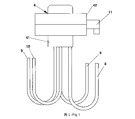
[0018] Fig.1 is a front view of an electric valve according to the invention.
[0019] Fig. 2 is a sectional view of an electric valve according to the
invention.
[0020] Fig. 3 is a front view of a valve seat (one outlet) of an electric
valve according to the
invention.
[0021] Fig. 4 is a sectional view along line A-A of Fig. 3.
[0022] Fig. 5 is a front view of a valve seat (two outlets) of an electric
valve according to the
invention.
[0023] Fig. 6 is a sectional view along line B-B of Fig. 5.
[0024] Fig. 7 is a front view of a valve seat (three outlets) of an electric
valve according to the
invention.
[0025] Fig. 8 is a sectional view along line C-C of Fig. 7.
4
22680275.1
CA 02881971 2015-02-12
CA Application
Blakes Ref: 12035/00001
[0026] Fig. 9 is a front view of a valve core (when the valve seat has one
outlet and two
outlets) of an electric valve according to the invention.
[0027] Fig. 10 is a sectional view along line D-D of Fig. 9.
[0028] Fig. 11 is a front view of a valve core (when the valve seat has three
outlets) of an
electric valve according to the invention.
[0029] Fig. 12 is a sectional view along line E-E of Fig. 11.
[0030] Fig. 13 is a state diagram when a valve seat (one outlet) and a valve
core of an electric
valve according to the invention are fitted in a cutoff state.
[0031] Fig. 14 is a sectional view along line F-F of Fig. 13.
[0032] Fig. 15 is a state diagram when a valve seat (one outlet) and a valve
core of an electric
valve according to the invention are fitted in a pressure relief state.
[0033] Fig. 16 is a sectional view along line G-G of Fig. 15.
[0034] Fig. 17 is a state diagram when a valve seat (one outlet) and a valve
core of an electric
valve according to the invention are fitted in an open state.
[0035] Fig. 18 is a sectional view along line H-H of Fig. 17.
[0036] Fig. 19 is a state diagram when a valve seat (two outlets) and a valve
core an electric
valve according to the invention are fitted in a cutoff state.
[0037] Fig. 20 is a sectional view along line Hof Fig. 19.
[0038] Fig. 21 is a state diagram when a valve seat (two outlets) and a valve
core an electric
valve according to the invention are fitted in a pressure relief state.
[0039] Fig. 22 is a sectional view along line J-J of Fig. 21.
[0040] Fig. 23 is a state diagram when a valve seat (two outlets) and a valve
core an electric
valve according to the invention are fitted in an open state.
[0041] Fig. 24 is a sectional view along line K-K of Fig. 23.
[0042] Fig. 25 is a state diagram when a valve seat (three outlets) and a
valve core of an
electric valve according to the invention are fitted in a cutoff state.
[0043] Fig. 26 is a sectional view along line L-L of Fig. 25.
[0044] Fig. 27 is a state diagram when a valve seat (three outlets) and a
valve core of an
electric valve according to the invention are fitted in a pressure relief
state.
[0045] Fig. 28 is a sectional view along line M-M of Fig. 27.
[0046] Fig. 29 is a state diagram when a valve seat (three outlets) and a
valve core of an
electric valve according to the invention are fitted in an open state 1.
22680275.1
CA 02881971 2015-02-12
CA Application
Blakes Ref: 12035/00001
[0047] Fig. 30 is a state diagram when a valve seat (three outlets) and a
valve core of an
electric valve according to the invention are fitted in an open state 2.
[0048] Fig. 31 is a state diagram when a valve seat (three outlets) and a
valve core of an
electric valve according to the invention are fitted in an open state 3.
[0049] Fig. 32 is a state diagram when a valve seat (three outlets) and a
valve core of an
electric valve according to the invention are fitted in an open state 4.
[0050] Fig. 33 is a pressure relief state diagram of a single-cycle
refrigerating system
according to the invention.
[0051] Fig. 34 is a pressure relief state diagram of a dual-cycle
refrigerating system according
to the invention.
[0052] Fig. 35 is a pressure relief state diagram of a triple-cycle
refrigerating system
according to the invention.
[0053] Reference numbers in Fig. 1-Fig. 35:
[0054] 1 Compressor; 2 One-Way Valve; 3 Condenser; 4 Electric Valve; 41 Valve
Seat; 411
Inlet; 412 Pressure Relief Port; 413 Outlet; 42 Electric Motor; 421 Stator;
422 Rotor; 4221
Mandrel; 43 Valve Cap; 44 Valve Core; 441 Diversion Slot; 442 Through Slot; 5
Capillary Tube;
51 First Capillary Tube; 52 Second Capillary Tube; 53 Third Capillary Tube; 6
Evaporator; 61
First Evaporator; 62 Second Evaporator; 63 Third Evaporator; 7 Pressure Relief
Channel; 8
Liquid Feeding Pipe; 9 Liquid Discharging Pipe; 10 Pressure Relief Tube; 11
Power Interface.
[0055] The invention will be further illustrated below by the embodiments in
conjunction with
the drawings.
DETAILED DESCRIPTION OF THE EMBODIMENTS
[0056] Referring to Fig. 1-Fig. 35, an electric valve includes a valve seat
41, an electric motor
42 and a valve cap 43; an inlet 411, a pressure relief port 412 and a
plurality of outlets 413 are
set on the valve seat 41, wherein the pressure relief port 412 and the outlets
413 are located on
the upper surface of the valve seat 41; the valve cap 43 is covered above the
valve seat 41; the
electric motor 42 is fixedly set on the valve cap 43, and the electric motor
42 includes a stator
421 and a rotor 422, wherein the stator 421 is set on the outer surface of the
valve cap 43, and
the rotor 422 is set in the intracavity of the valve cap 43; the central part
of the rotor 422 is
provided with a mandrel 4221, and the rotor 422 may rotate around the axis of
the mandrel 4221;
the lower end of the mandrel 4221 is fixedly provided with a valve core 44
that is opened with a
6
22680275.1
CA 02881971 2015-02-12
CA Application
Blakes Ref: 12035/00001
pressure-relief diversion slot 441 and a through slot 442, and the lower
surface of the valve core
44 contacts the upper surface of the valve seat 41, the pressure-relief
diversion slot 441 is
opened on the lower surface of the valve core 44, and the through slot 442
penetrates through
the valve core 44 along the thickness direction of the valve core 44.
[0057] An external power interface11 is further set on the stator of the
electric motor of the
electric valve, and the electric motor of the electric valve is powered by an
external power
source. The electric motor is a step motor. When the valve core 44 rotates,
the electric valve 4
may change among a cutoff state, an open state and a pressure relief state.
[0058] In the cutoff state, the pressure-relief diversion slot 441 and the
through slot 442 of the
valve core 44 are not in communication with any one of the outlets 413 of the
valve seat 41, and
the pressure relief port 412 and the outlets 413 are both blocked by the valve
core 44, and the
inlet 411 is not in communication with any one of the outlets 413 or the
pressure relief port 412.
[0059] In the open state, the through slot 442 of the valve core 44 is exactly
located above the
outlets 413, and the pressure relief port 412 is blocked by the valve core 44,
the through slot
442 of the valve core 44 is in communication with the outlets 413 of the valve
seat 41, the inlet
411 is in communication with the outlets 413 via the through slot 442 of the
valve core 44, and
the pressure relief port 412 is not in communication with the outlets 413 or
the inlet 411.
[0060] In the pressure relief state, the pressure-relief diversion slot 441 of
the valve core 44 is
exactly located above the outlets 413 and the pressure relief port 412, and
the through slot 442
is blocked by the valve seat 41, the pressure-relief diversion slot 441 of the
valve core 44 is in
communication with both the outlets 413 and the pressure relief port 412 of
the valve seat.
Because the pressure-relief diversion slot 441 is located on the lower surface
of the valve core
44 and does not penetrate through the valve core 44, the pressure-relief
diversion slot 441 only
internally communicate the pressure relief port 412 and the outlets 413, thus
the inlet 411 is not
in communication with any one of the outlets 413 or the pressure relief port
412.
[0061] A refrigerating system includes a compressor, a one-way valve, a
condenser, an
electric valve, a capillary tube and an evaporator, wherein the compressor,
the one-way valve,
the condenser, the electric valve, the capillary tube and the evaporator are
connected in turn in
the form of a ring, thereby forming a circulating refrigerating system. A
pressure relief port of the
valve seat of the electric valve is connected between the compressor and the
one-way valve via
the pressure relief tube, and when the electric valve is in a pressure relief
state, a small amount
of high-pressure gas from the exhaust port of the compressor to the one-way
valve can flow to
the low-pressure evaporator.
7
22680275.1
CA 02881971 2015-02-12
CA Application
Blakes Ref: 12035/00001
[0062] The valve seat is a echelon-form cylinder, wherein the diameter of the
lower cylinder is
larger than that of the upper cylinder; the lower cylinder is the seat body,
and the upper cylinder
is a cylindrical table set concentrically with the lower cylinder; the
pressure relief port and the
outlets are set on the top surface of the cylindrical table. The inlet is set
on the common
boundary of the cylindrical table and the valve seat, i.e., the intersection
part of the two. The
rotor is of a tubular form, and during assembling, the cylindrical table is
exactly located in the
intracavity of the rotor. At the same time, a blind hole is set at the center
of the cylindrical table,
so that the lower end of the mandrel will be inserted into the blind hole. The
rotor of the electric
motor may drive the mandrel and the valve core to rotate together.
[0063] The lower surface of the valve core contacts the upper surface of the
cylindrical table,
so that the valve core can exactly cover the pressure relief port and the
outlets of the valve seat.
Because the valve core is provided with a depressed pressure-relief diversion
slot and a
depressed through slot, the pressure relief port and the outlets can be made
in communication
with the pressure-relief diversion slot or the through slot by adjusting the
position of the valve
core. By controlling the rotation angle and rotation direction of the step
motor, the electric valve
may change among the above three states.
[0064] When the valve core turns to different positions by rotating at
different angles, the
communication state between the pressure relief port, the outlets and the
pressure-relief
diversion slot, the through slot will be changed. Because the inlet is located
at the boundary of
the cylindrical table and the valve seat, the refrigerant may enter from the
inlet into the valve
cavity enclosed by the valve cap and the valve seat. When the through slot on
the valve core is
in communication with the outlets on the valve seat, that is, when the
electric valve is in the
open state, the refrigerant in the condenser may flow out from the outlets,
thereby realizing the
circulation of the refrigerant in the refrigerating system.
[0065] When the valve core of the electric valve is in the initial position,
the valve core will
block both the pressure relief port and the outlets, and the refrigerant in
the condenser cannot
enter the outlets, and the electric valve will be in a closed state, i.e., the
above cutoff state, and
at this time, the refrigerant in the condenser cannot be circulated.
[0066] Then, by rotating the rotor and the valve core via the step motor, the
pressure relief
port and the outlets of the valve seat are both in communication with the
pressure-relief
diversion slot of the valve core, and the through slot is blocked, thus the
high-pressure gas in
the exhaust port of the compressor passes through the pressure relief tube,
the pressure relief
port, the outlets and the capillary tube in turn and thus flows to the low-
pressure evaporator; at
8
22680275.1
CA 02881971 2015-02-12
CA Application
Blakes Ref: 12035/00001
this time, the refrigerating system will be in the pressure relief state. A
small amount of
refrigerant between the exhaust pipe of the compressor and the one-way valve
may flow to the
low-pressure evaporator via the pressure relief loop, and one-way valve
"responds" rapidly to
realizing closing. On one hand, after the compressor is shut down, the high-
temperature and
high-pressure refrigerant in the condenser cannot pass through the electric
valve and flow into
the low-pressure and low-temperature evaporator; on the other hand, the high-
pressure
potential energy of the refrigerant in the condenser is maintained, and when
the compressor is
started again, it can refrigerate rapidly, thus the energy dissipation during
the starting and
stopping process of the compressor may be avoided.
[0067] Then, the valve core is continuously rotated, and when the valve core
is rotated to a
position where the through slot is in communication with the outlets, that is,
when the electric
valve is in the open state, the refrigerant in the valve cavity can flow out
from the outlets, so that
the refrigerant can flow from the condenser to the capillary tube and the
evaporator. At the same
time, the pressure relief port will be blocked by the valve core, so that the
refrigerant can only
flow to the capillary tube and the evaporator by the condenser.
[0068] The lower end of the valve seat is connected with a plurality of
pipelines that are in
communication with the inlet, the pressure relief port and the outlets, i.e.,
a liquid feeding pipe 8,
a pressure relief tube 10 and a liquid discharging pipe 9, respectively;
wherein, the number of
the outlets may be one or more, and correspondingly, the number of the liquid
discharging pipes
9 may also be one or more. The liquid feeding pipe 8, the pressure relief tube
10 and the liquid
discharging pipe 9 are fixedly connected with an interface at the lower end of
the valve seat and
are in communication with the inlet, the pressure relief port and the outlets
on the valve seat via
the corresponding channels in the valve seat. The refrigerant enters into the
electric valve via
the liquid feeding pipe and enters into the cavity enclosed by the rotor and
the valve seat. The
liquid feeding pipe is connected with the condenser, and the liquid
discharging pipe is connected
with the capillary tube. When the inlet is made in communication with the
outlets by the through
slot, the liquid feeding pipe will be in communication with the liquid
discharging pipe, and the
refrigerant may enter from the condenser into the capillary tube and the
evaporator via the
electric valve.
[0069] In the single-cycle refrigerating system, there exists only one outlet
and one liquid
discharging pipe. In the dual-cycle refrigerating system, there exist two
outlets and two liquid
discharging pipes. In the triple-cycle refrigerating system, there exist three
outlets and three
9
22680275.1
CA 02881971 2015-02-12
CA Application
Blakes Ref: 12035/00001
liquid discharging pipes. The liquid discharging pipe is connected with the
capillary tube via a
pipeline, thus the refrigerant is output to the capillary tube and the
evaporator.
[0070] In the electric valve of the invention, the functions of a
refrigerator, for example,
refrigerant bifurcation, cutoff and pressure relief, etc., may be realized by
rotating the valve core
of the electric valve to different positions, so that the high-pressure hot-
state refrigerant in the
condenser cannot enter into the evaporator after the compressor is shut down,
and the potential
energy in the high-pressure refrigerant may be kept, thereby the energy
dissipation in the
refrigerating system may be effectively reduced, and the object of energy
saving may be
attained; by using the pressure relief loop inside the valve core of the
electric valve, fast close
can be realized for the one-way valve at the moment the compressor is shut
down, the energy
saving effect and the stability of the refrigerating system can be improved,
and it has the
features of low noise and high stability. The valve core of the electric valve
is driven to rotate via
a step motor, thus the noise defect of the existing bistable solenoid valve
during a reversing
process may be overcome, and it has an advantage of low noise.
[0071] A lug is set under the rotor 422, and a stopper is further set on the
valve seat 41. The
rotor and the valve seat are positioned up and down, and the rotor is coupled
on the valve seat.
The rotor is tubular, and the lug is set under the outer wall of the rotor;
the tubular wall of the
rotor contacts with the edge part of the upper surface of the lower cylinder
of the valve seat; a
stopper is set at the edge part of the lower cylinder, and it exactly catches
the lug. When the
rotor rotates to a certain angle, the lug under the rotor will be exactly
blocked by the convex
stopper on the valve seat, thereby the rotation angle of the rotor will be
restricted.
[0072] A pressure-relief diversion slot and a through slot are designed on the
valve core, and
a pressure relief port and an outlet are designed on the valve seat. When the
valve core of the
electric valve rotates to the pressure relief state, the pressure relief port
and the outlet on the
valve seat of the electric valve are connected via the pressure-relief
diversion slot inside the
valve core, and the refrigerant in the pressure relief port may enter into the
outlet via the
pressure-relief diversion slot. When the electric rotary valve is in the
cutoff state, the pressure
relief port, the outlet and the inlet will be blocked by the valve core, and
the electric valve will be
in a completely closed state.
[0073] A "pressure relief loop" consisted of a pressure relief tube and a
pressure relief port,
which helps the compressor to start, is designed inside the valve core of the
electric valve, thus
the response capability of the one-way valve may be improved, the reliability
of reverse closing
may be improved, and the stability of the energy saving effect of the
refrigerator may be
22680275.1
CA 02881971 2015-02-12
CA Application
Blakes Ref: 12035/00001
improved. As a result, a plurality of functions, for example, refrigerant
bifurcation, pressure
maintaining and pressure relief, may be realized by one rotary valve.
[0074] The pressure-relief diversion slot 441 and the through slot 442 are
both kidney slots;
the pressure-relief diversion slot 441 is a straight-line slot, and the
through slot 442 is an arc slot.
The pressure-relief diversion slot extends in a straight line along the
surface of the valve core,
that is, the two lateral surfaces of the kidney slot are both flat surfaces,
except for the hemicycle
shapes at the two ends thereof. The through slot extends along the arc line of
the valve core, i.e.,
the two lateral surfaces of the through slot are both arc surfaces, except for
the hemicycle
shapes at the two ends thereof. Because the through slot has an arc surface
and the centers of
the two outlets are located one the same circumference, the through slot can
cover the two
outlets at the same time.
[0075] The number of the outlets 413 may be one, two or three, which may be
adjusted
according to the type of the refrigerating system.
[0076] A single-cycle refrigerating system provided with the above electric
valve includes a
compressor 1, a one-way valve 2, a condenser 3, an electric valve 4, a
capillary tube 5 and an
evaporator 6; wherein, the compressor 1, the one-way valve 2, the condenser 3,
the electric
valve 4, the capillary tube 5 and the evaporator 6 are connected in turn, one
end of the
evaporator 6 is connected with the capillary tube 5, and the other end of the
evaporator 6 is
connected with the compressor 1; the electric valve 4 is connected with an
exhaust port of the
compressor 1 via the pressure relief channel 7.
[0077] In the single-cycle refrigerating system, the electric valve is
adjusted to the open state
as the compressor is started, and the electric valve is adjusted to the
pressure relief state or the
cutoff state in the stage that the compressor is stopped. A pressure-relief
diversion slot and a
through slot are designed on the valve core, and a pressure relief port and an
outlet are
designed on the valve seat. The electric valve is provided with at least one
outlet, preferably,
one outlet; a liquid discharging pipe 9 is installed at the outlet. When the
valve core of the
electric valve rotates to the pressure relief state, the pressure relief port
and the outlet on the
valve seat of the electric valve are connected via the pressure-relief
diversion slot inside the
valve core, and the refrigerant in the pressure relief port may enter the
outlet via the
pressure-relief diversion slot. When the electric rotary valve is in the
cutoff state, the pressure
relief port, the outlet and the inlet will be blocked by the valve core, and
the electric valve will be
in a completely closed state. A "pressure relief loop" consisted of a pressure
relief tube and a
pressure relief port, which helps the compressor to start, is designed inside
the valve core of the
11
22680275.1
CA 02881971 2015-02-12
CA Application
Blakes Ref: 12035/00001
electric valve, thus the response capability of the one-way valve may be
improved, the reliability
of reverse closing may be improved, and the stability of the energy saving
effect of the
refrigerator may be improved. As a result, a plurality of functions, for
example, refrigerant
bifurcation, pressure maintaining and pressure relief, may be realized by one
rotary valve.
[0078] A dual-cycle refrigerating system provided with the electric valve
includes a
compressor 1, a one-way valve 2, a condenser 3, an electric valve 4, a
capillary tube 5 and an
evaporator 6; wherein, the compressor 1, the one-way valve 2, the condenser 3
and the electric
valve 4 are connected in turn; the capillary tube 5 includes a first capillary
tube 51 and a second
capillary tube 52, and the evaporator 6 includes a first evaporator 61 and a
second evaporator
62; the electric valve 4 is connected with the first evaporator 61 via the
first capillary tube 51,
and the electric valve is connected with the second evaporator 62 via the
second capillary tube
52; one end of the first evaporator 61 is connected with the first capillary
tube 51, and the other
end of the first evaporator 61 is connected with the second evaporator 62; one
end of the
second capillary tube 52 is connected with the electric valve 4, and the
second end of the
second capillary tube 52 is connected between the first evaporator 61 and the
second
evaporator 62; the second evaporator 62 is connected with the compressor 1;
the electric valve
4 is connected with an exhaust port of the compressor 1 via the pressure
relief tube 7. In the
dual-cycle refrigerating system, the electric valve is adjusted to the open
state as the
compressor is started, and the electric valve is adjusted to the pressure
relief state or the cutoff
state in the stage that the compressor is stopped. A pressure-relief diversion
slot and a through
slot are designed on the valve core, and a pressure relief port and an outlet
are designed on the
valve seat. The electric valve is provided with at least two outlets,
preferably, two outlets; the two
outlets correspond to two liquid discharging pipes 9 respectively. When the
valve core of the
electric valve rotates to the pressure relief state, the pressure relief port
and the outlets on the
valve seat of the electric valve are connected via the pressure-relief
diversion slot inside the
valve core, and the refrigerant in the pressure relief port may enter into the
outlets via the
pressure-relief diversion slot. When the electric rotary valve is in the
cutoff state, the pressure
relief port, the outlets and the inlet will be blocked by the valve core, and
the electric valve will be
in a completely closed state. A "pressure relief loop" consisted of a pressure
relief tube and a
pressure relief port, which helps the compressor to start, is designed inside
the valve core of the
electric valve, thus the response capability of the one-way valve may be
improved, the reliability
of reverse closing may be improved, and the stability of the energy saving
effect of the
12
22680275.1
CA 02881971 2015-02-12
CA Application
Blakes Ref: 12035/00001
refrigerator may be improved. As a result, a plurality of functions, for
example, refrigerant
bifurcation, pressure maintaining and pressure relief, may be realized by one
rotary valve.
[0079] A triple-cycle refrigerating system provided with the above electric
valve includes a
compressor 1, a one-way valve 2, a condenser 3, an electric valve 4, a
capillary tube 5 and an
evaporator 6; wherein, the compressor 1, the one-way valve 2, the condenser 3
and the electric
valve 4 are connected in turn; the capillary tube 5 includes a first capillary
tube 51, a second
capillary tube 52 and a third capillary tube 53, and the evaporator 6 includes
a first evaporator
61, a second evaporator 62 and a third evaporator 63; the electric valve 4 is
connected with the
first evaporator 61 via the first capillary tube 51, the electric valve 4 is
connected with the
second evaporator 62 via the second capillary tube 52, and the electric valve
4 is connected
with the third evaporator 63 via the third capillary tube 53; one end of the
first evaporator 61 is
connected with the first capillary tube 51, and the other end of the first
evaporator 61 is
connected with the third evaporator 63; one end of the second evaporator 62 is
connected with
the second capillary tube 52, and the other end of the second evaporator 62 is
connected with
the third evaporator 63; one end of the third capillary tube 53 is connected
with the electric valve
4, and the other end of the third capillary tube 53 is connected between the
first evaporator 61
and the third evaporator 63; the third evaporator 63 is connected with the
compressor 1; the
electric valve 4 is connected with an exhaust port of the compressor 1 via the
pressure relief
channel 7.
[0080] In the triple-cycle refrigerating system, the electric valve is
adjusted to the open state
as the compressor is started, and the electric valve is adjusted to the
pressure relief state or the
cutoff state in the stage that the compressor is stopped. The first evaporator
61, the second
evaporator 62 and the third evaporator 63 are respectively a cold preservation
evaporator, a
temperature changing evaporator and a freezing evaporator. The first
evaporator, the second
evaporator and the third capillary tube are connected on the same end of the
third evaporator.
The first evaporator and the first capillary tube form a first branch, the
second evaporator and
the second capillary tube form a second branch, and the third capillary tube
forms a third branch,
wherein the first branch, the second branch and the third branch are connected
in parallel to
form a parallel structure, one end of the parallel structure is connected with
the electric valve,
and the other end thereof is connected with the third evaporator; that is, the
parallel structure is
connected in series between the electric valve and the third evaporator. The
electric valve is
provided with at least three outlets, preferably, three outlets; the three
outlets correspond to
three liquid discharging pipes 9 respectively; the three liquid discharging
pipes are connected
13
22680275.1
CA 02881971 2015-02-12
CA Application
Blakes Ref: 12035/00001
with three capillary tubes respectively, for outputting the refrigerant to the
three evaporators
respectively. The refrigerant from the first outlet and the second outlet
passes through the first
evaporator and the second evaporator, and then enters into the third
evaporator. A pressure
relief loop is formed by the pressure relief port and the pressure relief
channel of the electric
valve, thus the response capability of the one-way valve may be improved, the
reliability of
reverse closing may be improved, and the stability of the energy saving effect
of the refrigerator
may be improved. As a result, a plurality of functions, for example,
refrigerant bifurcation,
pressure maintaining and pressure relief, may be realized by one rotary valve.
14
22680275.1