Note: Descriptions are shown in the official language in which they were submitted.
CA 02882326 2015-02-12
WO 2014/153612
PCT/AU2014/000328
- I -
AIR-COOLED MODULAR LNG PRODUCTION FACILITY
FIELD OF THE INVENTION
The present invention relates to an air-cooled liquefied natural gas
production process for
producing a product stream of liquefied natural gas at a production location
using a
plurality of modules. The present invention further relates to an air-cooled
liquefied
natural gas production plant for producing a product stream of liquefied
natural gas at a
production location using a plurality of modules.
BACKGROUND TO THE INVENTION
Natural gas ("NO") is routinely transported from one location to another
location in its
liquid state as "Liquefied Natural Gas' (LNG). Liquefaction of the natural gas
makes it
more economical to transport as LNG occupies only about 1/600th of the volume
that the
same amount of natural gas does in its gaseous state. After liquefaction. LNG
is typically
stored in cryogenic containers either at or slightly above atmospheric
pressure. LNG is
regasified before distribution to end users through a pipeline or other
distribution .network
at a temperature and pressure that meets the delivery requirements of the end
users.
Wellhead gas is subjected to gas pre-treatment to remove contaminants prior
1:0
20. liquefaction. The hydrogen sulphide and carbon dioxide can be removed
using a suitable
process such as amine adsorption. Removal of water can be achieved using
conventional
methods, for example, a molecular sieve. Depending on the composition of
contaminants
present in the inlet gas stream, the inlet gas stream may be subjected to
further pre-
treatment to remove other contaminants, such as mercury and heavy hydrocarbons
prior.
to liquefaction. Liquefaction is achieved using methods that are well
established in the art
which typically involve compression and cooling. Such processes include the
APCI
C3/Me" or Sp111MR1v or APXTM. processes, the ConocoPhillips Optimized Cascade
Process, the Linde Mixed Fluid Cascade process or the Shell Double Mixed
Refrigerant
or Parallel Mixed Refrigerant process. Regardless of the choice of
liquefaction process,
.30. refrigerants are used to reduce the temperature of the treated
wellhead gas to a
temperature of around -160'C to form LNG, resulting in warming of the
refrigerant which
must be compressed for recycic to the liquefaction process. The compressors
used for this
CA 02882326 2015-02-12
WO 2014/153612
PCT/AU2014/000328
duty are traditionally steam turbines, gas turbines or electric motors
depending on the
power requirements and layout issues of a. particular LNG production facility.
The
coolers required for the various compression and heat exchanger operations
associated
with an LNG plant may be an coolers or water coolers arranged in a heat
exchanger bank.
Prior art modularised LNG production trains have been closely based upon the
design and
layout of the more traditional stick-built LNG production trains. Until now,
modularisation has been conducted by slicing up an existing stick built LNG
train design
into transportable sections, leading to some compromises regarding the
placement of the
module boundaries. Prior art examples of modularization of a traditional stick-
built air-
cooled LNG train have relied on dividing the centrally located air-cooled heat
exchanger
bank into the smallest number of modules possible for a given size of air
cooler within the
air-cooled heat exchanger bank. The result is that the other process equipment
is located
in separate stand-alone modules as illustrated schematically in FIG 1(a). The
disadvantage of this approach is a large number of piping connections between
the air-
cooled heat exchangers and the other associated processing equipment.
There remains a need to explore alternative designs for a modular LNG
production plant
to alleviate this problem.
SUMMARY OF THE INVENTION
According to a first aspect of the present invention there is provided a
liquefied natural
gas production process. for producing. a product stream of liquefied natural
gas at a
production location, said process comprising:
2.5 a) designing a plurality of modules for installation at the
production location to form
an installed production train, each module having a module base for mounting a
plurality
of plant equipment associated with a selected function associated with the
production of
liquefied natural gas; :said selected function being assigned to said module,
the plurality of
modules including a first module assigned to perform a first selected
function, and, a
.30. second module assigned to perform a second selected function;
(b) designing an air-cooled heat exchanger bank for the installed production
train,
the heat exchanger bank including:. a first row of air-cooled heat exchanger
bays, and, an
CA 02882326 2015-02-12
WO 2014/153612
PCT/AU2014/000328
- 3 -
adjacent parallel second row of air-cooled heat exchanger bays;
(c) arranging a first sub-section of the first row of heat exchanger bays at.
an elevated
level vertically offset from and towards a first edge of a first module base
to .form a
covered section of the first module base, the first module base being designed
and sized to
include an uncovered section for mounting a selected piece of process
equipment,
wherein the first module includes the first sub-section of the first row of
heat exchanger
bays without including a sub-section of the second row of heat exchanger bays;
(d) arranging a first sub-Section of the second row of heat exchanger bay.4 at
an
elevated level vertically offset from and towards a first edge of .a second
module base to
provide a covered section of the second module base, wherein the second module
includes the first sub-section of the second row of heat exchanger bays
without including
a sub-section of the first row of heat exchanger bays; and,
(e) positioning the first edge of the second module bage at the production
location
towards the first edge of the first module base.
in one form, the selected piece of equipment is; a rotating piece of equipment
associated
with a circulating refrigerant, a piece of equipment having a flammable
inventory, a long
lead-time piece of equipment, or, a piece of equipment having an overall
height -that is
taller than the height of the elevated level.
In one form, the process further comprises the step of sizing the second
module base to
include an uncovered section for mounting a selected piece of proees
equipment. In one
form, the selected piece of equipment is; a rotating piece of equipment
associated with a
circulating refrigerant, a piece of equipment having a flammable inventory, a
long lead-
time piece of equipment or, a piece of equipment having an overall height that
is taller
than the height of the elevated level,
in one form, the first module base has a rectangular footprint comprising two
long sides
and two short sides and the first edge of the first module base is arranged
along one of the
.30. two long sides. In one form, the second module base has a rectangular
footprint
comprising two long Sides and two short sides and the first edge of the second
module
base is arranged along one of the two long sides. In one form, the first
module- base has a
CA 02882326 2015-02-12
WO 2014/153612
PCT/AU2014/000328
- 4 -
rectangular footprint comprising two long sides and two short sides and the
first edge of
the .first module base is arranged along one of the two short sides. In one
form, the
second module base has a rectangular footprint comprising two long sides and
two short
sides and the first edge of the second module base is arranged along one of
the two short
sides. M. one form, a second sub-section of the first or second row of heat
exchanger
hays is positioned on an adjacent module.
In one form, the first module is one of a plurality of first modules. In one
form, the second
module is one of a plurality of second modules.
In one form, the process further comprises the step of constructing at least
one of the.
plurality of modules at a construction location or assembling at least one of
the plurality
of modules at an assembly location prior to transport to the production
location, and
testing the at least one module for verification purposes at the construction
or assembly
location.
In one form, the installed production train has a longitudinal axis extending
from a first
end of the installed production train to a second end of the installed
production train and
the first row of heat exchanger bays is arranged in a straight line parallel
or perpendicular
to the longitudinal axis of the installed production train. In one form, the
installed
production train has a longitudinal axis extending from a first end of the
installed
production train to a second end of the installed production train and the
second row of.
beat exchanger bays is arranged in a straight line parallel or perpendicular
to the
longitudinal axis of the installed production train.
In one form, the first Sub-section of the first row of heat exchanger bays is
the first row of
heat exchanger bays. In one form, the first sub-section of the second row of
heat
exchanger bays is the second row of heat exchanger bays: In one form, the
first sub-
section of the first row of heat exchanger bays is arranged to extend
outwardly beyond the
.30. first edge of the first module base, and a gap is 'formed between the
first module base and
the second module base during step (d). In one form, the first sub-section of
the second
row of heat exchanger bays is arranged to extend outwardly beyond the first
edge of the
CA 02882326 2015-02-12
WO 2014/153612
PCT/AU2014/000328
- 5 -
second module base, and a gap is -formed between the first module base and the
second
module base during step (d).
In one form, the first sub-section of the first row of heat exchanger bays and
the first sub-
section of the second row of heat exchanger bays is arranged to extend
outwardly beyond
the first edge of the second module base, and a gap is formed between the
first module
base and the second module base during step (d).
In one form, the process further comprises the steps of arranging a plurality
of third
module heat exchangers operatively associated with a third selected function
on a third
module base to form a portion of the first row of heat exchanger bays and a
portion of the.
second row of heat exchanger bays, the plurality of third module heat
exchangers being
arranged on an elevated level vertically offset from the third module base to
provide a
covered section of the third module base. In one form, the process further
comprises the
step of sizing the third module base such that the plurality of third module
heat
exchangers covers at least 90% of the third module base to form a fully
covered third
module. In one form, the third module is one of a plurality of third modules.
In one form, one of the plurality of modules is a pre-treatment module for
removing
contaminants .from a natural gas feed stream to produce a pre-treated natural
gas stream.
one form, one of the plurality of modules is a first refrigerant condenser
module for
pre-cooling a pre-treated natural gas stream to produce a pre-cooled gas
stream and a. first
refrigerant vapour stream. In one form, one of the plurality of modules is a
first
refrigerant compression module .for compressing a first refrigerant vapour
stream to
produce a compressed first refrigerant stream for recycle to a first
refrigerant condenser
module. In one form, one of the plurality of modules is a liquefaction module
operatively
associated with a main cryogenic heat exchanger for further cooling a pre-
cooled gas
stream through indirect heat exchange with a second refrigerant to produce .a
liquefied
natural gas product stream and a second refrigerant vapour stream. In one
form, one of
.30. the plurality of modules is a second refrigerant compression module
for compressing a
second refrigerant vapour stream to produce a compressed second refrigerant
stream for
recycle to a .main cryogenic heat exchanger. In one form, the first
refrigerant is propane
CA 02882326 2015-02-12
WO 2014/153612
PCT/AU2014/000328
- 6 -
or nitrogen. In one form, the second refrigerant is a mixed refrigerant
hydrocarbon
mixture or nitrogen. In one form, the production location is onshore, offshore
OD a
floating facility, offshore on a fixed facility, barge-mounted or grounded
facility.
According to a second aspect of the present invention there is provided a
liquefied natural
gas production plant for producing a product stream n of liquefied natural gas
installed at a
production location comprising:
a plurality of modules designed for installation at the production location to
form an
installed production train, each module having a module base for mounting a
plurality of
plant equipment associated with a selected function associated with the
production of
liquefied natural gas, said selected function being assigned to said module,
the plurality of
modules including a first module assigned to perform a first selected
function, and, a
second module assigned to perform a second Selected function;
an air-cooled heat exchanger bank designed for the installed production train,
the
heat exchanger bank including: a first row of air-cooled heat exchanger bays,
and, an
adjacent parallel second row of air-cooled heat exchanger bays;
a first sub-section of the first row of heat exchanger bays arranged at an
elevated
level vertically offset from and towards a first edge of a first module base
to fOrD1 a
covered section of the first module base, the first module base being designed
and sized to
include an uncovered section for mounting a selected piece of process
equipment,
wherein the first module includes the 'first sub-section of the first row of
heat exchanger
bays without including a sub-section of the second row of heat exchanger
bar,.;:
a first sub-section of the second row of heat exchanger bays arranged at an
elevated
level vertically offset from and towards a first edge of a second module base
to provide a
covered section of the second module base, wherein the second module includes
the first
sub-section of the second row of heat exchanger bays without including a sub-
section of
the first row of heat exchanger hays; and,
the first edge of the second module base positioned at the production location
towards the first edge of the first module base.
In one form, the selected piece of equipment is; a rotating piece of equipment
associated
with, a circulating refrigerant, a piece of equipment having a flammable
inventory, a long
CA 02882326 2015-02-12
WO 2014/153612
PCT/AU2014/000328
- 7 -
lead-time piece of equipment. or, a piece of equipment having an overall
height that is
taller than the height of the elevated level.
In one form, the second module base is sized to include an uncovered section
for
mounting a selected piece of process equipment. In one form, the selected
piece of
equipment is; a rotating piece of equipment associated with a circulating
refrigerant, a
piece of equipment having a flammable inventory, a long lead-time piece of
equipment,
or, a piece of equipment having an overall height that is taller than the
height of the
elevated level.
In one form, the first module base has a rectangular footprint comprising two
long sides
and two short sides and the first edge or the first module base is arranged
along one of the
two long sides. In one form, the second module base has a rectangular
footprint
comprising two long sidles and two short sides and the first edge of the
second module
base is arranged along one of the two long sides. In one him', the first
module base has a
rectangular footprint comprising two long sides and two short sides and the
first edge of
the first module base is arranged along one of the two short sides. In one
form, the
second module base has a rectangular footprint comprising two long sides and
two short
sides and the first edge .of the second module base is arranged along one of
the two short
sides.
hi one form, a second sub-section of the first or second row of heat exchanger
bays is
positioned on an adjacent module.
2.5 In one form, the first module is one of a plurality of first modules.
In one form, the
second module is one of a plurality of second modules.
in one form, the installed production train has a longitudinal axis extending
from a first
end of the installed production train to a second end of the installed
production train and
.30. the first: row of heat exchanger bays is arranged in a straight line
parallel or perpendicular
to the longitudinal axis of the installed production train.
CA 02882326 2015-02-12
WO 2014/153612
PCT/AU2014/000328
- 8 -
in one form, the installed production .train has a longitudinal axis extending
from a first
end of the installed production train to a second end of the installed
production train and
the second row of heat exchanger bays is arranged in a straight line parallel
or
perpendicular to the longitudinal axis of the installed production train.
In one form, the first sub-section of the first row of heat exchanver bays is
the first row of
heat exchanger bays. In one form, the first sub-section of the second row of
heat
exchanger bays is the second row of heat exchanger bays,
In one form, the first sub-section of the first row of heat exchanger bays. is
arranged to
extend outwardly beyond the first edge of the first module base, and a gap is
formed
between the first module base and the second module. In one form, the first
sub-section of
the second tow of heat exchanger bays is arranged to extend outwardly beyond
the first
edge Of the second module base, and. a gap is formed between the first module
base and
the second module base. In one form, the first sub-section of the first row of
heat
exchanger bays and the first sub-section of the second row of heat exchanger
bays is
arranged to extend outwardly beyond the first edge of the second module base,
and a gap
is formed between the first module base and the second module base during step
(d).
In one form, the production plant further comprises a plurality of third
module heat
exchangers operatively associated with a third selected function arranged on a
third
module base to form a portion of the first row of beat exchanger bays and a
portion of the
second row of heat exchanger bays, the plurality of third module heat
eschangers being
arranged on an elevated level vertically offset from the third module base to
provide a
covered section of the third module base, in one form, the third module base
is sized such
that the plurality of third module heat exchangers covers at least 90% of the
third module
base to form a fully covered third module. In one form, the third module is
one of a
plurality of third modules.
.30. In one form, one of the plurality of modules is a pre-treatment module
for removing
contaminants from a natural gas feed stream to produce a pre-treated natural
gas stream.
In one form, one of the plurality of modules is a first refrigerant condenser
module for
CA 02882326 2015-02-12
WO 2014/153612
PCT/AU2014/000328
- 9 -
pre-cooling a pre-treated natural gas stream to produce a. pre-cooled gas
stream and a first
refrigerant vapour stream. In one form, one of the plurality of modules is a
first
refrigerant compression module for compressing a first refrigerant vapour
stream to
produce a compressed first refrigerant stream for recycle to a first
refrigerant condenser
module. In one form, one of the plurality of modules is a liquefaction module
operatively
associated with a main cryogenic heat exchanger for further cooling a pre-
cooled gas
stream through indirect heat exchange with a second refrigerant to produce a
liquefied
natural gas product stream and a second refrigerant vapour stream, In one
form, one of
the plurality of modules is a second refrigerant compression module .for
compressing a
second refrigerant vapour stream to produce a compressed second refrigerant
stream for
recycle to a main cryogenic beat exchanger.
In one form, the first refrigerant is propane or nitrogen. In one forth, the
second
refrigerant is a mixed refrigerant hydrocarbon mixture or nitrogen.
In one form, the production location is onshore, offshore on a floating
facility, offshore on
a fixed facility, barge-mounted or grounded facility.
BRIEF DESCRIPTION OF THE DRAWINGS
In order to facilitate a more detailed understanding of the nature of the
invention several
embodiments of the present invention will now be described in detail, by way
of example
only, with reference to the accompanying drawings, in which;
FIG. 1(a) is a schematic plan view of a prior art production train;
1(b) is a schematic plan view of the prior art production train of FIG, 1.(a)
with
light grey shading to illustrate the location of the first row of heat
exchanger hap and
dark grey Shading to illustrate the location of the second row of heat
exchanger hay..;
FIG. 2(a) is a schematic plan view of an alternative prior art production
train;
FIG, 2(b) is a schematic plan .view of the prior art production train of FIG.
2(a) with
light grey shading to illustrate the location of the first row of heat
exchanger bays and
.30. dark grey shading to illustrate the location of the second row of heat
exchanger bays;
FIG. 3(a) is an isometric view from one direction of one of the plurality of
modules
of an LNG production train of the present invention showing a first module
designed and
CA 02882326 2015-02-12
WO 2014/153612
PCT/AU2014/000328
- 10 -
sized to include a covered section and an uncovered section;
HQ, 3(b) is a plan view of the module of FIG. 3(a);
FIG, 4(a) is an isometric view from one direction of one of the plurality of
modules
of an LNG. production train of the present invention showing a fully covered
module
without an uncovered section;
FIG. 4(b) is a plan view of the module of FIG. 4(a)
FIG. 5(a) is a schematic plan view of one embodiment of the present invention
showing a first module with a covered and uncovered section and a second fully
covered
module;
FIG, 5(b) is a schematic side view of the embodiment of FIG, 5(a)1
FIG, 6(a) is a schematic plan view of one embodiment of the present invention
showing a first module with a covered and uncovered section and a second
module with a
covered and uncovered section;
FIG. 6(b) is a schematic side view Of the embodiment Of FIG. 6(a);
FIG. 7 is a schematic plan view of one embodiment of the present invention
showing
a first module with a covered and uncovered section and a second fully covered
module;
Fla 8 is a schematic plan view of one embodiment of the present invention
showing
a first modulo with a covered and uncovered section and a second module with a
covered
and uncovered section;
FIG. 9(a) is a schematic plan view of one embodiment of the present invention
showing two first modules, each with a covered and uncovered section, two
Tully covered
second modules and, and a third module;.
9(h) is a schematic plan view (if one embodiment: of the present invention in
which a first row of heat exchanger bays is shaded in light grey and in which
a second
2.5 row of heat exchanger bays is shaded in dark grey;
FIG. 9(c) is a schematic plan view of one embodiment of the present invention
in
which a first section of the first row of heat exchanger hays is shaded in
light grey and in
which a second plurality of heat exchangers operatively associated with the
second
selected function on the second module base is shaded in dark grey;
.30 FIG. .10 is a schematic plan view of one embodiment of the present
invention
showing two first modules, each with a covered and uncovered section, one
second
module with a covered and uncovered section, One fully covered second. module,
and a
CA 02882326 2015-02-12
WO 2014/153612
PCT/AU2014/000328
- 11 -
third module;
HQ, 11 is a schematic plan view of one embodiment of the present invention
showing two first modules, each with a covered and uncovered section, two
second
modules, each with a covered and uncovered section, and, a third module;
FIG, 12 is a schematic plan view of one embodiment of the present invention
showing two first modules, each with a covered and uncovered section, two
second
modules, each with a covered and uncovered section, and, an additional module
arranged
towards one end of the installed production train;
FIG. 13 =is. a schematic plan view of one embodiment of the present invention
showing one first module, including a first section of the first row of heat
exchanger bays,
one second module including a first section of the second row of heat
exchanger bays
which comprises the whole of the second row of heat exchangers bays, and two
additional
modules including heat exchanger bays which together with those in the first
module
comprise the first row of heat exchanger bays in a staggered manner;
FIG. 14 is a schematic plan view of one embodiment of the present invention
showing one first module, including a first section of the first row of heat
exchanger bays
which comprises the whole of the first row of heat exchangers bays, one second
module,
including a 'first section of the second row of heat exchanger bays, and two
additional
modules including heat exchanger bays which together with those in the second
module
comprise the second row of heat exchanger bays, arranged in a linear manner;
FIG. 15 is a schematic plan view of one embodiment of the present invention
showing one first 'module, one second module, one third module, one fourth
module and
one fifth module;
FIG, 16 is a schematic plan view of another embodiment of the present
invention
showing one first module, one .second module, one third module, one fourth
module and
one fifth module;
FIG. 17 is a schematic plan view of one embodiment of the present invention
showing one first module, two second modules, one third module, one fourth
module and
one fifth module;
.30. FIG. 18 is a
schematic plan view of one embodiment of the present invention
showing one first module with a covered .and uncovered section, one fully
covered second
module, and two fully covered third modules;
CA 02882326 2015-02-12
WO 2014/153612
PCT/AU2014/000328
- 1., -
FIG. 19 is a= schematic plan view of one embodiment of the present invention
showing one first module with a covered and uncovered section, one second
module with.
a covered and uncovered section, and two fully covered third modules;
FIG. 20 is a schematic side view of one embodiment of the present invention
showing the first sub-section of the first row of heat exchanger bays
extending outwardly
beyond the first edge of .the first module base to form a gap between the
first module base
and the second module base;
FIG, 21 is a schematic side view of one embodiment of the .present invention
showing the first sub-section of the second row of heat exchanger bays
.arranged to extend
outwardly beyond the first edge of the second module base to form a gap
between the first
module base and the second module base; and.
FIG. 22 is a schematic side view of one embodiment of the present invention
showing both the first section of the first row of heat exchanger bays manged
to extend
outwardly beyond the first edge of the first module base and the first section
of the second
row of heat exchanger bays arranged to extend outwardly beyond the first edge
of the
second module base to form a gap between the first. module base and the second
module
base.
DETAILED DESCRIPTION OF PARTICULAR EMBODIMENTS
The present invention may be understood more readily by reference to the
following
detailed description of the invention taken in connection with the
accompanying drawing
figures, which form a part of this disclosure. It is to be understood that the
present
invention is not limited to the specific devices, methods, conditions or
parameters
described and/or shown herein, and that the terminology used herein is for the
purpose of
describing particular embodiments by way of example only and is not intended
to be
limiting of the claimed invention. Also, as used in the specification
including the
appended claims, the singular forms "a,' "an," and "the" include the plural,
and .reference
to a particular numerical value includes at least that particular value,
unless. the context
clearly dictates otherwise. Unless defined otherwise, all technical and
scientific terms
.30. used herein have the same meanings as commonly understood by one of
ordinary skill in
the art to which this invention belongs. Like reference, numerals refer to
like parts.
CA 02882326 2015-02-12
WO 2014/153612
PCT/AU2014/000328
- 13 -
The term "LNG" refers to liquefied natural .gas,
The term "production train" refers to facilities used for the pre-treatment of
a natural gas
feed stream to remove contaminants and facilities used or receiving pre-
treated gas and
subjecting the pre-treated gas to cooling to form liquefied natural gas.
The term "heat exchanger bay" refers to a heat exchanger having a plurality of
tubes
extending between flow headers with fluid being caused to flow through the
plurality of
tubes to exchange heat with a heat exchange medium that passes across the
outside of the.
plurality of tubes. The term "air-cooled heat exchanger bay" refers to a heat
exchanger
bay having a single row of fans (usually 2-4) arranged within each heat
exchanger bay
between the headers to direct the flow of air across the plurality of tubes.
The term "heat exchanger bank" refers to a collection of air-cooled heat
exchanger bays
arranged adjacent to each other in a single or double row.
The term "stick-built" or "off-module" refers to a plant or a section of a
plant that is
constructed predominantly on a production location which the plant is intended
to occupy
upon completion of construction of the plant. In contiast, the tetm "module"
refers to a
section of a plant that is pre-assembled at a construction or assembly
location remote
from the production location. Each module is designed to be transported from
the
construction or assembly location to the production location by towing or on
floating
barges or by land using .rail or truck. After each module is moved from the
construction
or assembly location to the production location, the module is positioned in a
suitable pre-
determined orientation to suit the needs of a given LNG production facility.
Before describing various embodiments of the present invention, two examples
of prior
art modular LNG production facilities will be briefly described. The first
example is
illustrated schematically in FIG. 1(a) and FIG. 1(b). The second example is
illustrated
.30. schematically in FIG. 2(a) and 2(b) and is the subject of a co-owned
and co-pending
patent application. Referring to FIG. 2(a) and 2(b), the facility includes
Prior Art Module
A (1), Prior Art Module. B (2), Prior Art Module C (3), Prior Art Module D
(4), and, Prior
CA 02882326 2015-02-12
WO 2014/153612
PCT/AU2014/000328
- 14 -
Art Module E (5), To keep the o \=erall plot site of the LNG production
facility to a
minimum, it is known to arrange sub-sections of the air-cooled heat exchanger
bank (6)
over the top of selected modules so as to cover one hundred percent of the
area defined by
the base of said module with a view to making the air-cooled heat exchanger
bank as
large as possible for a given module size. Prior Art Module C (3) is
completely covered,
whilst the other four modules extend beyond the sides of the air-cooled heat
exchanger
bank (6) in order to provide uncovered space to accommodate other processing
equipment. The air-cooled heat exchanger bank (6) is made up of a first row of
heat
exchanger bays (7) and a second row of heat exchanger bays (8). The first and
second
rows of heat exchanger bays extend parallel to each other along the full
length of the
production facility. For clarity purposes only, the first row of heat
exchanger bays in FIG
2(b) is shaded in light grey with the second row of heat exchanger bays shaded
in dark
grey. As is best seen from. FIG. 2(b), each of Prior Art Module A (1), Prior
Art 'Module
B (2), Prior Art. Module C (3), Prior Art Module D (4), and., Prior Art Module
E (5)
include a portion of the first row of heat exchanger bays (7) and a portion of
the second
row of heat exchanger bays 00. In the prior art arrangement illustrated in FIG
1(a), the
air-cooled heat exchanger bank (6) is analogously made up of a first row of
heat
exchanger bays (7) and a second row of heat exchanger bays (8). For clarity
purposes
only, the first .row of heat exchanger bays in FIG 1(b) is shaded in. light
grey with the
second row of heat exchanger bays shaded in dark grey. As is best seen from
FIG. 1(b),
each of Prior Art Module A. (1), Prior Art Module B (2)õ and, Prior Art Module
C (3)
include a portion of the first row of heat exchanger bays (7) and a portion of
the second
row of heat exchanger bays (8). The present invention has been developed in
part to
provide an alternative to these prior art air-cooled heat exchanger bank
arrangements.
A first embodiment of the present invention is now described with reference.
to FIGS. 3 to
5 which schematically show a liquefied natural gas production process (10) for
producing
a product stream of liquefied natural gas at a production location (12). The
process
includes designing a plurality of modules (14) for installation at the
production location
.30. (12) to form an installed production train (16) having a longitudinal
axis (22). Each
module (14) has a module base (18) for mounting a plurality of plant equipment
(20)
associated with a selected function associated with the production of
liquefied natural gas,
CA 02882326 2015-02-12
WO 2014/153612
PCT/AU2014/000328
- 15 -
said selected function being assigned to said module (14). The plurality of
modules (14)
includes at least; a first module (24) assigned to perform a first selected
function, a
second module (26). assigned to perform a second selected function, and,
optionally, a
third module (30) :assigned to perform a third selected function. The number
of modules
within the plurality of modules may vary. By way of example, in the
embodiments
illustrated in FIGS. 5-6, the production train (16) comprises three modules
with the first
module (24) and the second module (26) shown in solid lines :and the third
module (30)
shown in dotted lines to indicate that this modules is optional Or able to be
added to the
installed production train :at a later date. In the embodiment illustrated in
Fl-G. 7, the
production train (16) comprises three modules. In the embodiment illustrated
in FIG. 8,
the production train (16) comprises four modules with two shown in solid lines
and two
shown in dotted lines to indicate that these modules are optional or able to
he added to the
production train at a later date. In the embodiment illustrated in -FIG. 9,
the production
train (16) comprises five modules.
The process of the present invention includes the step of designing an air-
cooled heat
exchanger bank (32) including: a first row of heat exchanger bays (34) and, an
adjacent
parallel second row of heat exchanger bays (36). Referring to FIG. 3(a) and
3(b), the
process of the present invention includes the step of arranging a first sub-
section (38) of
20- the first row of heat exchanger bays (34) at an elevated level (40)
vertically offset from
and towards a first edge (42) of the first module base (44). This arrangement
is used to
provide a covered section (46) of the first module base (44). This arrangement
is used to
minimize the plot space required for the production train (16) and improve
efficiency of
air cooling by way of improved circulation. In addition to this, the first
module base is
designed and sized to include an uncovered section (48) for mounting a
selected piece of
process equipment (50). The selected piece Of equipment (50) may be selected,
from the
group including, but not limited to: a rotating piece of equipment associated
with a
circulating refrigerant, a piece of equipment having a flammable inventory, a
long lead-
dine piece of equipment, or, a piece of equipment having an overall height
that is taller
than the height of the elevated level (40).
CA 02882326 2015-02-12
WO 2014/153612
PCT/AU2014/000328
- 16 -
When the first module (24) is installed at the production location, .the first
edge (42) of the
first module base (44) is positioned $o that the first sub-section (38)
.forrns part of the first
row of heat exchanger bays (34) of the installed production train (16).
AdvantageouSly,
the uncovered section (48) of the first module base (44) is further positioned
away from
the longitudinal axis of the installed production train (22) than the covered
section (46) as
best seen in FIG. 5. Using this arrangement, the uncovered section of the
first module
base allows unobstructed overhead crane access to the selected pieces of
equipment as
well as improved side access making construction Or maintenance activities for
the
selected pieces of equipment easier to perform. Sizing the first module base
to include an
uncovered section in addition to the covered section, allows for installation
and
positioning of the selected pieces of equipment in a. less congested area of
the module
which has the flow-on benefit of allowing the selected pieces of equipment to
he the last
pieces of equipment that are installed on the module. Sizing the first module
base to
include an uncovered section in addition to the covered section, also allows
entire
processing systems that include both air-cooled heat exchangers and other
types of
processing equipment that cannot be installed beneath the air-cooled heat
exchanger bank
to be installed within the same module. This allows all of the interconnecting
pipes
between those related equipment items to be completed as part of module
fabrication,
thus eliminating the need to complete the pipowork at the production location
which
provide significant cost and time savings over the prior art.
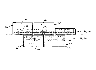
Referring to FIG, 4(a) and 4(b) and FIG. 5, the process includes the step of
arranging a
first sub-section (56) of the second row of heat exchanger bays (36) at an
elevated level
(40) vertically offset from and towards a first edge (58) of the second module
base (60).
This arrangement is used to provide a covered section (62) of the second
module base
(60). When the second module (26) is installed at the production location, the
first edge
(58) of the second module base (60) is positioned so that the first sub-
section (56) forms
part of the second row of heat exchanger bays (36) of the installed production
train (16),
.30. In embodiment illustrated in FIG, 4(a), 4()) and FIG 5, the covered
section (62) of the
second module base (60) comprises at least 90% of the second module base. In
an
alternative embodiment illustrated in FIG. 6, the second module base (60) is
designed, and
CA 02882326 2015-02-12
WO 2014/153612
PCT/AU2014/000328
- 17 -
sized to include a covered section (62) and an uncovered section (64). The
uncovered
section (64) may he provided for mounting the selected piece of process
equipment (50)
on the second module base (60). As can be seen from FIG. 6, when the second
module is
installed at the production location, the first edge (58) of the second module
base (60) is
positioned so that the first sub-section (56) forms part of the second row of
heat
exchanger bays (36) of the installed production train (16) with the result
that the covered
section (62) of the second module base (60) is positioned closest to the
longitudinal axis
(22) of the installed production train (16) whilst the uncovered section (62)
of the second
module base (60) is positioned away from the longitudinal axis (22) of the
installed
production train (16).
The module base (18) of each of the plurality of modules (1.4) may have a
generally
rectangular or square footprint. When the first module base (44) has a
rectangular
footprint comprising two long sides (68) and two short sides (70), the first
edge (42) of
the .first module base (44) may be arranged along one of the two long sides
(68) as shown
in FIG. 5 and 6 or, alternatively, may be arranged along one of the two short
sides (70) of
the first module base (44) as shown in FIG. 7 and FIG. 8. In an analogous
manner, when
the second module base (60) has a rectangular footprint comprising two long
sides (72)
and two short sides (74), the first edge (58) of the second module base (60)
may be
20. arranged along one of the two long sides (72) as shown in FIG. 5 and 6
or, .alternatively,
may be arranged along one of the two short sides of the first module base (74)
as shown
in FIG. 8. In the embodiment illustrated in FIG. 7, the first edge (42) of the
first module
base (44) is arranged along a short side (70) whilst the first edge (58) of
the second
module base (60) is arranged along one of the two long sides (72). In each
embodiment,
the first edge (58) of the second module base (60) is positioned at the
production location
towards the first edge (42) of the first module bast (44).
in all embodiments of the present invention, the air-cooled heat exchanger
bank (36) is
desigmed so that the first module (24) does not include any heat exchanger
from the
second row of heat exchanger bays (42) and the second module (26) does not
include any
heat exchanger from the first row of heat exchanger bays (40). To illustrate
this, FIG.
9(a) shows an installed production train comprising two first modules (24' and
24"), two
CA 02882326 2015-02-12
WO 2014/153612
PCT/AU2014/000328
- 18 -
second modules (26' and 26") and a third module (30). FIG. 9(b) shows the
installed
production train of FIG. 9(a) with the entire first row of heat exchanger bays
(34) shaded
in light grey and the entire second row of heat exchanger bays (36) shaded in
dark grey
for clarity purposes. In an analogous manner, FIG. 9(e) shows only the first
sub-section
(38) of the first row of heat exchanger bays. (34) is shaded in light grey for
clarity
purposes. In the event that there is insufficient space available on the
second module base
(60) to accommodate the heat exchangers required to perform the second
selected duty,
the first sub-section (56) of the second row of heat exchanger bays (36) is
Arranged on the
second module base (60) whilst a second sub-section (76) of the second row of
heat
exchanger bays (36) is positioned on an adjacent third module (30). By way of
example,
the second module may be a propane condenser module which requires a large
number of
heat exchangers to be included in the second plurality of heat exchangers
(56). FIG. 9(e)
shows the first sub-section (56) and the second sub-section (76) of the second
row of heat
exchanger bays (36) shaded in dark grey for clarity purposes. It is apparent
from FIG.
9(a) and 9(b), that the first module (24') includes a first sub-section of the
first row of
heat exchanger bays (34) without including a first sub-section of the second
row of heat
exchanger 'bays (36).
Referring to FIG. 7, the process may include the step of arranging a plurality
of third
module heat exchangers (80) operatively associated with the third selected
function of the
third module (3(1) on the third module base (82). The plurality of third
module heat
exchangers (80) includes both a second section (84) of the first row of heat
exchanger
bays (34) and a second section (76) of the second row of heat exchanger bays:
(36). The
plurality of third module heat exchangers are arranged on an elevated level
(40) vertically
offset from the third module base (82) to provide a covered section (86) of
the third
module base (82). In this embodiment, the third module base.(82) is sized such
that the
plurality of third module heat exchangers (80) covers at least 90% of the
third module
base to form a fully covered third module. As best seen in FIG. 7, the third
module (30)
includes sections of both the first and second rows of heat exchanger bays. In
the
.30. embodiment illustrated in FIG. 8, the third module is one of a
plurality of third modules
with two third modules (30' and 30") shown.. Each of the third modules (30'
and 30")
includes sections of both the first and second rows of heat exchanger bays.
One of the
CA 02882326 2015-02-12
WO 2014/153612
PCT/AU2014/000328
- 19 -
third modules (30') is arranged at a first end (88) of the installed
production train (1.6) and
the other third module (30") is arranged at a second end (90) of the installed
production
train (16).
The procesN of the present invention allows for constructing at least one of
the plurality of
modules at a construction location or assembling at least one of the plurality
of modules
at an assembly location prior to transport to the production location, and
testing the at
least one module for verification purposes at the construction or assembly
location.
Within each module, the pieces of equipment required to perform the pre-
determined
function assigned to that module are arranged to minimize interfaces between
modules so
as to minimize the hook-up that is required to be completed when the modules
are
delivered from a construction location or assembly location to the production
location. In
this way, a module can be, essentially self-contained and provided with a
temporary
control system to allow the module to be switched on for loop checks and
commissioning
at the construction or assembly location prior to transport to the production
location.
Upon arrival at the production location, wireless control may he used for
inter-modular
communication and control to further reduce the hook-up time. At a production
location
where it is important to minimize the length of interconnecting pipe tuns
between
modules, the plurality of modules are spaced as closely as possible, while
still. allowing
sufficient room at the production location to hook up the interconnections
between
modules.
Further alternative embodiments are illustrated in FIG. 10 to FIG. 19 for
which like
references refer to like parts. In each of the embodiments illustrated in FIG.
10, FIG. 11,
and FIG. 12, the first module is one of a plurality of first modules with two
first modules
(24' and 24") being shown by way of example only. The second module is
similarly one
of a plurality of second modules with two second modules (26' and 26") being
shown by
way of example only, only with one third module (30). In FIG. 11, all of the
first modules
and all of the second modules include covered and uncovered sections whilst in
FIG. 10,
one of the plurality of second modules (26') is fully covered by a first sub-
section of the
second row of heat exchanger bays. FIG, 12 illustrates that the module bases
of adjacent
first and second modules may be offset relative to each other along the
longitudinal axis
CA 02882326 2015-02-12
WO 2014/153612
PCT/AU2014/000328
- 20 -
of the installed production .train.
Whilst it is preferable for one or both of the first row di heat exchanger
bays or the
second row of heat exchanger bays to be arranged in a straight line as
illustrated in FIG. 5
to 12, this is not essential. In the embodiment illustrated in .FIG. 13, the
first row of heat
exchanger bays (34) which is designated by an arrow labelled with reference
numeral (35)
is non-linear and the second row of heat exchanger bays 06) is comprised
entirely of the
first sub-section (56) of the second row of heat exchanger bayS (36). In other
words, all of
the second row of 'heat exchanger bays (34) is provided on the second module-
base (61A
hi the embodiment illustrated in 'FIG. 14, the first sub-section (38) of the
first row of heat
exchanger bays (34) is the first row of heat exchanger bays (34). In other
words, all of
the first row of heat exchanger bays (34) is provided on the first module base
(44).
In the embodiments illustrated in FIG. 15 and FIG 16, the installed production
train (16)
includes one first module (24), one second module (26), one third module (30),
a fourth
module (92) and a fifth module (94). Each of the third, fourth and fifth
modules are
designed to include a sub-seci ion of the first row of heat exchanger bays
(34) and a sub-
section of the second row of heat exchanger bays (6). In the embodiment
illustrated in
FIG. 15, both the fourth module and the fifth module include a covered section
(96) and
an uncovered section (98). Each uncovered section (98) is provided for
mounting of one
or more selected pieces of equipment (50) in an analogous manner to that
described
above. In the embodiment illustrated in FIG. 16, both the fourth module and
the fifth
module include a covered section (96) and two uncovered sections (98' and
98"). Each
uncovered section (98) is paw ided for mounting of one or more selected pieces
of
2.5 equipment (Si)) in an analogous manner to that described above.
The embodiment illustrated in FIG, 17 shows one first module (2.4), two second
modules
(26' and 26"), one third module (30), one fourth module (92) and one fifth
module (94).
The embodiment illustrated in FIG. 18 shows one first module (24) with a
covered and
.30. uncovered section, one fully covered second module (26), and two fully
covered third
modules (30' and 30"). The embodiment illustrated in FIG. 19 shows one first
module
(24) with a covered and uncovered section, one second module (26) with a
covered and
CA 02882326 2015-02-12
WO 2014/153612
PCT/AU2014/000328
- -
uncovered section, and two fully covered third modules (30' and 30"). As with
all other
embodiments, the first module (24) includes a first sub-section of the first
row of heat
exchanger bays :04) without including a first sub-section of the second row of
heat
exchanger bays (36) and the second module (26) includes a first sub-section of
the second
row of heat exchanger hays (36) without including a Nection of the first row
of heat
exchanger bays (36).
In the embodiments illustrated in FIG. 20, the first sub-section (38) of the
first row of heat
exchanger bays (34) is arranged to extend outwardly beyond the first edge (42)
of the first
module base (44). Using this arrangement, when the first edge (42) of the
first module
base (44) is positioned towards the first a first edge (58) of the second
module base (60)
to form the installed production train (16), the first sub-section (38) of the
first row of
heat exchanger bays (34) is adjacent to the first sub-section (56) of the
second row of heat
exchanger bays (36), whilst leaving a gap (97) between the first module base
(44) and the
second module base (60). In the embodiment illustrated in FIG. 21, the first
sub-section
(56) of the second row of heat exchanger bays (36) is arranged to extend
outwardly
beyond the first edge <58) of the second module base (60) to form the gap
(97). In the
etnbodiment illustrated in FIG. 22, the first sub-section (38) of the first
row of heat
exchanger bays (3.4) is arranged to extend outwardly beyond the first edge
(42) of the first
module base (44), and, the first sub-section (56) of the second row of heat
exchanger bays
(36) is arranged to extend outwardly beyond the first edge (58) of the second
module base
(60) to form the gap (97). Advantageously, the gap (97) provides room for
underground
services. (99), .for example, electrical cables, to come up within the
installed production.
train (16) without having a module positioned over them,
One embodiment. of the use of the production train (16) for the production of
LNG is now
described with reference to FIG, 11, by way of example only. In .general
terms, a process
for liquefying a natural gas stream comprises the steps of:
i) pre-treating a natural gas feed stream in a pre-treatment module (100) to
produce u
.30. pre-treated natural gas stream;
ii) pre-cooling the pre-treated natural gas stream in a first refrigerant
compression
module (102) to produce a pre-cooled gas stream and a first refrigerant vapour
stream
CA 02882326 2015-02-12
WO 2014/153612
PCT/AU2014/000328
- 2') -
which is compressed therein;
iii) condensing the first refrigerant vapour stream in a first refrigerant
condenser
module (104) to produce a compressed first refrigerant stream for recycle to
step ii);
iv) further cooling the pre-cooled gas stream in a main cryogenic heat
exchanger
(106) operatively associated with a liquefaction module (108) through indirect
heat
exchange with a second refrigerant to produce a liquefied natural gas product
stream and
a second refrigerant vapour stream; and,
v) compressing the Second refrigerant vapour stream in a Second refrigerant
compression module (110) to produce a compressed second refrigerant stream for
recycle
to step iv).
Referring to FIG. ii, the production train (16) comprises the following
modules:
a) a pretreatment module (100);
b) a first refrigerant compression module (102), in this example, a propane
compression module;
c) a first refrigerant condenser module (104), in this example, a propane
condenser module;
d) a.liqnefaction module (I08); and,
e) a second refrigerant compression module (110), in this example, a mixed
refrigerant (MR) compression module.
For comparison purposes only, the equivalent modules of a production train of
the prior
art are marked up in FIG. 2(a) with reference numerals 100, 102, 104, 108 and
1.10.
In embodiment of the present invention now described with reference to FIG.
11, the first
refrigerant is propane while the second refrigerant is a mixed refrigerant
hydrocarbon
mixture, by way of example only. This type of process is known as the propane
pre-
cooled mixed refrigerant, or C.31VIR process, which is used to manufacture
most of the
LNG produced worldwide and is a process that is not further discussed here is
it
.30. considered to be well known to the person skilled in the art. When using
propane as the
first refrigerant, care is taken to ensure that propane does not leak because
propane vapour
is highly flammable. Using the proms= of the present invention, the process
equipment
CA 02882326 2015-02-12
WO 2014/153612
PCT/AU2014/000328
- 23 -
required for propane compression is grouped together within a propane
compression
module to facilitate the pre-commissioning and commissioning of that module
having
all of the accessories that are needed to circulate fluid through the
compressor at the
construction or assembly location. To further improve safely, the main
rotating equipment
associated with the propane compression circuit is placed on an uncovered
section of one
of the plurality of modules rather than underneath the plurality of heat
exchangers
arranged on the elevated level.
In the embodiment illustrated in FIG. 11, the pretreatment module (1()()) is a
first module
(24"), the first refrigerant compression module (102) is a second module
(26'), and the
first refrigerant condenser module (104) is a third module (30). In addition
to this the.
liquefaction module (108) is a first module (24") and the second refrigerant
compression
module (11(i) is a second module (26"). In terms of construction scheduling,
the
compressors are long lead items. This embodiment allows for the installation
of the
pretreatment module (100) and first refrigerant condenser module (104) to
occur at the
production location (12) without needing to wait for the installation of the
first refrigerant
compression module (102). In an analogous manner, the liquefaction module
(108) can
be installed at the production location (12) without the need to wait .for the
installation of
the second refrigerant compression module (110).
This arrangement allows for direct fluid communication between the first
refrigerant
compression module (102) and the first refrigerant condenser module (104)
without the
need for the first .refrigerant to be piped across the pretreatment module
(100). This
arrangement further allows for direct fluid communication between the second
refrigerant
compression module (110) and the first refrigerant condenser module (104).
Thus in order
for the second refrigerant to be cooled by the first refrigerant in heat
exchangers either
inside or adjacent to the first refrigerant compression module (102), it only
has to pass
through one intermediate module, the first refrigerant condenser module (104),
rather than
both the first refrigerant condenser module (104) and the liquefaction module
(108). This
.30. is an advantage of the present invention compared to the prior art
illustrated in FIG. 2(0.
This arrangement further allows for direct fluid communication between the
liquefaction
module (108) and the end of the LNG trains, from which the LNG will be piped
to the
CA 02882326 2015-02-12
WO 2014/153612
PCT/AU2014/000328
- -)4 -
LNG storage tank. Thus the LNG product stream does not need to pass through
the
second refrigerant compression module (110). This is an advantage of the
present
invention compared to the prior art illustrated in FIG. 2(a).
The arrangement illustrated in FIG. 1.1 allows..a section of selected pipework
(120) that
runs along the length of the installed production train (16) to be completed
with fewer
hook-ups at the production location (12). For example, raw feed gas must be
piped to the
gas pretreatment module (100) which is positioned towards the first end (88)
of the
production train (16). If the interconnections with the main plant piperack
(122) occur at
the second opposite end (90) of the installed production train (16), the raw
feed gas
pipework (120) will need to traverse through only two -unrelated modules (108
and 104).
In contrast, using the prior art arrangement illustrated in FIG. 2(a), the
same service
would have to pass through four unrelated modules (110, 108, 104 and 102). In
addition
to the direct site labour savings, reducing the need for unrelated pipes to
pass through
modules assists to reduce the duration of the design process. The layout of
the plurality of
modules can be advanced and .completed without having to wait for additional
details
about unrelated services.
In the embodiment illustrated in FIG. 11, the pre-treatment module is one of
two first
modules (24') and the first module base (44)1s sized to include a covered
section (46) for
mounting of the first sub-section (38) of the first row of heat exchanger bays
(34) and an
uncovered section (48). for mounting one or more selected pieces of process
equipment
(50), such as an acid gas removal unit column and its associated knock-out
vessel and
pumps, and/or one or more molecular sieve dehydration vessels.
In the embodiment illustrated in FIG, 11, the first refrigerant compression
module (102) is
one of two second modules (26'). The second module base (60) is sized to
include a
covered section (62) for mounting of first sub-section (56) of the second row
of heat
exchanger bays (36) and an uncovered section (64) for mounting a selected
piece of
.30. process equipment (50'), such one or more first refrigerant
compressors.
In the embodiment illustrated in FIG. 11, the first refrigerant condenser
module (104) is a
CA 02882326 2015-02-12
WO 2014/153612
PCT/AU2014/000328
- 25 -
third module (30) because this module requires a comparatively large number of
heat
exchangers to be included in the plurality of third module heat exchangers
(8(Y) compared
with the other modules. In these embodiments, the first refrigerant condenser
module
(104) is aligned with the longitudinal axis (22) of the installed production
train (16) to
accommodate its requirement to include a second sub-section (84) of the first
row of heat
exchanger bays (34) and a second sub-section (76) of the second row of heat
exchanger
bays (36). The first refrigerant condenser module (104) may include services
that contain
non-flammable inventories, such as steam for heating purposes Or water for
either heating
or cooling purposes within the installed production train, The plurality of
plant equipment
required for these services may be mounted underneath the first refrigerant,
condenser
without significant safety risks due to potential leakage.
In the embodiment illustrated in FIG. 11, the liquefaction module 0 00 is one
of two first
modules (24"). The process .may include the step of locating the main
cryogenic heat
exchanger (106) off-module adjacent to the liquefaction module (108) due to
its size and
weight, delivery schedule', and/or to mitigate the potential for damage during
transport.
Alternatively, the main cryogenic heat exchanger (106) may be .positioned on
the
uncovered section (48") of the first module base (44"). Static equipment and
pumps
which are operatively associated with the main cryogenic heat exchanger are
positioned
on the liquefaction module (108) on the same side of the heat exchanger bank
as the .main
cryogenic heat exchanger to minimise interconnecting piping runs. Equipment
(50")
associated with end-flash gas compression, nitrogen and helium removal may
also be
positioned on the uncovered section (48') of the liquefaction module (1081 if
required.
An end-flash gas compression system (107) requires only very few heat
exchangers with
the result that the liquefaction module (104) has space available for
additional heat
exchangers which are operatively associated with another system,
A selected function that may require additional space is the first refrigerant
condenser,
which makes positioning the liquefaction module (108) in direct contact with
the first
.30. refrigerant condenser module (104) advantageous, If required, the
second sub-section
(84) of the first row of heat exchanger bays (34) which includes heat
exchangers that are
operatively associated with the first refrigerant condenser module (104) may
span across
CA 02882326 2015-02-12
WO 2014/153612
PCT/AU2014/000328
- 26 -
to partially cover the module base (144") of the adjacent liquefaction module
(108).
The second compression module (1.10) is one of the two second modules (26").
The
second compression module includes all of the process equipment required to
perform the
functional requirement of this module including the gas turbine, the
compressor,
interconnecting pipewoti. waste heat recovery, and recycle valves which are
arranged on
the module base. The plurality of heat exchangers operatively associated with
the second
compression module provides the required -aftercooling and intercooling for
the second
refrigerant compressors. In this embodiment, the second compression module
(110)
includes .an uncovered section (64") of sufficient .size to accommodate one or
more
refrigerant compressors (u13).
Each module has been designed to ensure that the main hydrocarbon inventories
and all
rotating equipment are positioned on the uncovered sections of the modules and
not
underneath the elevated heat exchanger bank. This permits good access for
maintenance
and allows the long lead items to be incorporated into the. modules late in
the construction
sequence. The significantly reduced hydrocarbon inventory provides improved
safety by
way of making it easier to deal with the consequence of a leak. In addition to
this, the
overall layout of the production train of the ptesent invention is designed to
for
modularisation, with small compact equipment selected to suit modularisation
rather than
adopting the prior art approach of relying on economy of scale. Instead,
smaller, more
intensive equipment has been selected in order to be able to lit more items
inside modules
of a limited size and weight One example of selecting smaller, more intensive
equipment
that is easier to modularise is the main refrigerant gas turbines. The
starting point for this
2.5 work was to utilise smaller more efficient aero-derivative gas turbines
that can be
completely integrated into modules of a practical Size. Aero-derivative gas
turbines have
been integrated into the modules, complete with the all of the elements of
each
compression system. This permits the complicated, large-diameter compressor
suction
and discharge lines to be built at a construction location rather than having
to be stick-
built at the production location, whilst retaining a practical total module
size/weight
Using Smaller units and keeping the gas turbine and. compressor integrated in
the same
module minimises the number of connections at site, and it also makes it
possible for the
CA 02882326 2015-02-12
WO 2014/153612
PCT/AU2014/000328
-27 -
compression system to be fully tested up to a nitrogen test run stage at the
construction or
assembly location. This extra level of commissioning and testing at the
construction or
assembly location is beneficial in reducing the amount of carry-over work that
has to be
done at a .significantly higher labour rate at the production site. The
variable speed nature
of the aem-derivative gas turbines simplifies the compressor start-up and
eliminates the
need to depressurise refrigerant. Removing the need for starter/helper motors
for gas
turbines used in prior art LNG trains also significantly reduces the maximum
electrical
power demand of the modularized LNG train and helps to keep the module size
down,
The production location can be onshore, offshore on a floating facility,
offshore on a
fixed facility, or a barge-mounted or grounded facility, provided only that
the heat
exchanger bank is an air-cooled heat exchanger bank. By way of example, the
modules
may be floated-in using steel or concrete gravity based structures with
integrated LNG-
storage, loading and boil-off gas re-liquefaction functionality with gas
Supplied to the
production 'location -via a subsea pipeline. The LNG plant may further include
optional
treatment steps such as product purification steps (helium removal, nitrogen
removal) and
non-methane product production steps (de-ethanizing, de-propanizing, sulphur
recovery)
if desired. The natural gas feed stream may be produced at and obtained from a
natural
gas or petroleum reservoir. As an alternative, the natural gas feed stream may
also be
obtained from another source, also including a synthetic source such as a
Fischer-Tropsch
process wherein methane is produced from synthesis gas.
It will be clearly understood that, although a number of prior art
publications are referred
to herein, this reference does not constitute an admission that any of these
documents
forms part of the common general knowledge in the. art, in Australia or in any
other
country. In the summary- of the invention, the description and claims which
follow,
except where the context requires otherwise due to express language or
necessary
implication, the word "comprise" or variations such as "comprises" or
"comprising' is
used in an inclusive sense, i.e. to specify the presence of the stated
features but not to
.30. preclude the presence or addition of further features in various
embodiments of the
invention.