Note: Descriptions are shown in the official language in which they were submitted.
CA 02882584 2015-02-19
- 1 -
CRYOGENIC PUMP OPERATION FOR CONTROLLING HEAT
EXCHANGER DISCHARGE TEMPERATURE
Field of the Invention
100011 The present application relates to a technique of operating a cryogenic
pump
for controlling the discharge temperature of a fluid from a heat exchanger.
Background of the Invention
100021 Gaseous fuels can be stored at cryogenic temperatures when employed as
fuel
for internal combustion engines. A gaseous fuel is defined as any fuel that is
in a gas
state at standard temperature and pressure which is defined herein as 1
atmosphere and
between 20 and 25 degrees Celsius. The gaseous fuel is stored near its boiling
point in a
storage vessel. For example, for methane at a storage pressure of about 1
atmosphere it
can be stored in liquefied form at a temperature of about -161 degrees
Celsius. Natural
gas is a mixture of gasses with methane typically comprising the largest
fraction, storage
temperature can vary, but is normally close to that of methane. From the
storage vessel
the liquefied gas is pumped in a liquid state towards and through a heat
exchanger where
the temperature of the gaseous fuel is increased. Depending upon gaseous fuel
pressure at
the inlet of the heat exchanger, the gaseous fuel is normally in either the
liquid state or
supercritical state as it enters the heat exchanger, and either the
supercritical state or gas
state as it leaves. It is also possible that the gaseous fuel can be in the
two phase state
when the temperature and pressure are at or near the critical point. There are
advantages
to storing the gaseous fuel in a liquefied state. The density increases when
the gaseous
fuel is in the liquid state compared to either the supercritical state or the
gas state
requiring a smaller volume to store an equivalent amount of fuel on an energy
basis.
Since liquids are relatively incompressible compared to gases, it is more
efficient to
pressurize a gaseous fuel when in the liquid state compared to the gas state.
After
vaporization in the heat exchanger a fuel injection system receives vaporized
gaseous fuel
and introduces it, either directly or indirectly, to one or more combustion
chambers in the
CA 02882584 2015-02-19
- 2 -
engine. As used herein, vaporizing refers to at least increasing the enthalpy
(that is,
temperature) of the gaseous fuel as it pass through the heat exchanger, and
depending
upon the pressure and the temperature of the gaseous fuel it can also refer to
changing the
state of the gaseous fuel to the gas state. While natural gas (LNG) is an
exemplary
gaseous fuel, which is employed in many high horse power (marine, mining,
locomotive)
and heavy duty engine applications, other gaseous fuels are equally applicable
to the
technique described herein.
[0003] A heat source is required in the heat exchanger to increase the
temperature of
the gaseous fuel above its boiling point. Engine coolant from the water jacket
of the
internal combustion engine can be employed as the heat source. The engine
coolant is
routed through a separate path in the heat exchanger such that waste heat from
combustion is transferred to the liquefied gaseous fuel from the storage
vessel causing it
to vaporize. By employing waste heat from the combustion process efficiency is
improved compared to employing energy derived from the engine output, for
example
such as electrical energy from a generator driven by the engine.
[0004] It is important to control the temperature of the gaseous fuel
discharged from
the heat exchanger for a number of reasons. First, the gaseous fuel discharged
from the
heat exchanger is normally required to be in a particular state, for example
the
supercritical state. Second, the temperature must be above a predetermined
minimum
value such that components downstream from the heat exchanger are protected
from
excessively cold temperatures that may cause component failure. When the
temperature
of gaseous fuel downstream of the heat exchanger drops below the predetermined
minimum value, or if it is predicted to drop below the predetermined minimum
value,
then the pump transferring gaseous fuel from the storage vessel to the heat
exchanger
must be suspended (stopped). Delivery of gaseous fuel to the fuel injection
system stops
when the pump stops and available fuel injection pressure decreases below the
requisite
level as the engine continues to consume fuel. As available fuel injection
pressure
CA 02882584 2015-02-19
- 3 -
decreases the engine can be designed to continue operation with a derated
power output
and then eventually stop, or go to a back-up secondary fuel. This situation is
not
desirable.
100051 It is possible for the temperature of gaseous fuel discharged from the
heat
exchanger to decrease below the predetermined minimum value when the engine
coolant
is too cold, or when the residence time of the gaseous fuel inside the heat
exchanger is
too short, or due to a combination of these two reasons. During normal engine
operating
conditions engine coolant temperature is maintained between a predetermined
range.
However, engine coolant temperature can deviate from this range for a variety
of reasons.
One such reason is cold start of the engine when engine coolant temperature is
equivalent
or near to ambient temperature, which is much lower than engine coolant
temperature
during normal engine operating conditions. Excessively cold ambient
temperatures may
also cause engine coolant temperature to drop below the predetermined
temperature
range, or at least worsen cold start performance.
100061 The volume of gaseous fuel inside the heat exchanger can be less than
the
maximum displacement volume of the pump, although this is not a requirement.
For
example, in high pressure direct injection applications where diesel is
employed as a pilot
fuel, the volume of gaseous fuel inside the heat exchanger is normally less
than the
maximum displacement volume of the pump since the engine can be fuelled with
diesel
on start-up and as the engine coolant warms up the engine can switch over to
the gaseous
fuel. In low-pressure spark-ignited applications, where the gaseous fuel is
port or
manifold injected, the volume of gaseous fuel inside the heat exchanger is
normally
greater than the maximum displacement volume of the pump since the engine is
fuelled
with gaseous fuel immediately on start-up and more residence time is needed
for the
gaseous fuel inside the heat exchanger to increase the enthalpy of the gaseous
fuel when
the engine coolant temperature is below normal engine operating conditions.
Under
normal engine operating conditions the temperature differential between engine
coolant
CA 02882584 2015-02-19
- 4 -
and the liquefied gaseous fuel inside the heat exchanger is sufficient to
completely
vaporize the gaseous fuel discharged from the heat exchanger. However, when
the
engine coolant is too cold the residence time of the gaseous fuel inside the
heat exchanger
is insufficient to effect its vaporization. Depending upon engine operating
conditions,
there is a need to increase the residence time of the gaseous fuel inside the
heat exchanger
to increase its temperature above a predetermined value, whether the volume
inside the
heat exchanger is greater than or less than the maximum displacement volume of
the
pump.
100071 One technique to increase residence time of the gaseous fuel inside the
heat
exchanger is to decrease pump speed. However, there is a corresponding
decrease in the
flow rate of gaseous fuel when pump speed is decreased, which can cause fuel
pressure
downstream of the heat exchanger to drop or cause unwanted fuel pressure
fluctuations.
Normally, the engine is not running at full load and the pump does not need to
be
stroking continuously without suspension. It is possible under these
conditions to
decrease pump speed to increase residence time of the gaseous fuel in the heat
exchanger.
However, in systems where the pump is directly driven from the engine it is
not possible
to change pump speed apart from a change in engine speed.
[0008] Canadian Patent No. 2,809,495 co-owned by the Applicant and issued June
3,
2014 to Batenburg et al., hereinafter Batenburg, discloses a technique of
controlling the
temperature of a fluid discharged from a heat exchanger. A cryogenic pump is
operated
in a plurality of modes. In a first mode, the cryogenic pump discharges a
first amount of
fluid from the heat exchanger in every pump cycle. The temperature that
correlates to the
fluid downstream from the heat exchanger is monitored, and when the
temperature drops
below a predetermined level the cryogenic pump is operated in a second mode
where a
second amount of fluid is discharged from the cryogenic pump for every pump
cycle,
where the second amount is less than the first amount. The residence time of
the
cryogenic fluid in the heat exchanger increases in the second mode, by pumping
a smaller
CA 02882584 2015-02-19
- 5 -
amount of fluid in every pump cycle, such that more heat is transferred to the
fluid
thereby increasing the discharge temperature. For each pump cycle, cryogenic
liquid is
drawn into a pumping chamber through an inlet check valve as a piston retracts
during a
suction stroke, and is then pumped through an outlet check valve by the piston
as it
extends during a compression stroke. In the second mode, no matter the
quantity of
cryogenic fluid that is discharged from the pump and vaporizer, the piston in
the pump
completes one suction stroke and one compression stroke, and the inlet and
outlet check
valves are open and closed respectively during the suction stroke and closed
and open
respectively during the compression stroke. As the inlet check valve opens
cryogenic
liquid fills the volume between the piston and cylinder head of the pump when
the pump
begins the intake stroke, and there is a corresponding pressure decrease in
the cryogenic
liquid in the pump. As the cryogenic liquid comes into contact with the
interior walls of
the pump and the piston it absorbs heat. Due to the pressure decrease and heat
absorption,
a portion of the cryogenic flashes each time the inlet check valve is opened,
which
reduces the volumetric efficiency of the pump. It is desirable to minimize the
number of
pumping cycles required to pump a predetermined mass of LNG to reduce the
amount of
LNG that flashes within the pump to increase the volumetric efficiency of the
cryogenic
pump.
[0009] There is a need for an improved technique of operating a cryogenic pump
when controlling the discharge temperature of a vaporizer. The present method
and
apparatus provide a technique for improving operation of an internal
combustion engine
fuelled with a liquefied gaseous fuel.
Summary of the Invention
100101 An improved method of operating a cryogenic pump for controlling
discharge
temperature of a heat exchanger that vaporizes a process fluid received from
the
cryogenic pump comprises monitoring at least one of process fluid temperature
and
working fluid temperature of a working fluid of the heat exchanger; retracting
a piston
CA 02882584 2015-02-19
- 6 -
during an intake stroke from a proximate cylinder head near a fuel inlet to a
distal
cylinder head away from the fuel inlet; and extending the piston in a
plurality of
incremental discharge strokes until the piston travels from the distal
cylinder head back to
the proximate cylinder head. At least one of the process fluid temperature and
the
working fluid temperature is maintained above a predetermined level.
[0011] The process fluid is a cryogenic fluid, and in an exemplary embodiment
the
process fluid is a gaseous fuel and the working fluid is engine coolant of an
internal
combustion engine. The gaseous fuel can be at least one of biogas, butane,
ethane,
hydrogen, landfill gas, methane, natural gas, propane and mixtures of these
fuels.
[0012] The process fluid temperature can be one of vaporized cryogenic fluid
temperature downstream of the heat exchanger; and a high-side temperature of a
heat
exchange region inside the heat exchanger. The working fluid temperature can
be one of
heat exchange fluid temperature upstream of the heat exchanger; and heat
exchange fluid
temperature downstream of the heat exchanger.
[0013] Stroke lengths for two or more of the incremental discharge strokes can
be
equal within a predetermined range of tolerance. Stroke length for each
incremental
discharge stroke can be determined as a function of at least one of the
process fluid
temperature and the working fluid temperature. The piston can be at rest
between
respective incremental discharge strokes, and at least two rest periods
between respective
incremental discharge strokes are equal within a predetermined range of
tolerance. Each
rest period time interval between respective incremental discharge strokes can
be
determined as a function of at least one of the process fluid temperature and
the working
fluid temperature. Alternatively, or additionally, piston velocity between
incremental
discharge strokes can be greater than zero and less than piston velocity
during
incremental discharge strokes.
CA 02882584 2015-02-19
- 7 -
[0014] An improved fuel supply system for supplying gaseous fuel to an
internal
combustion engine comprises a cryogenic pumping apparatus for pumping the
gaseous
fuel from a supply of gaseous fuel in a liquid state and a heat exchanger
receiving and
vaporizing the gaseous fuel from the cryogenic pumping apparatus and supplying
the
gaseous fuel to the internal combustion engine. The cryogenic pumping
apparatus has a
piston reciprocating between a proximate cylinder head near a fuel inlet and a
distal
cylinder head away from the fuel inlet. There is a controller operatively
connected with
the cryogenic pumping apparatus and programmed to command the cryogenic
pumping
apparatus in a pumping cycle to retract the piston during an intake stroke
from the
proximate cylinder head to the distal cylinder head and extend the piston in a
plurality of
incremental discharge strokes until the piston travels from the distal
cylinder head back to
the proximate cylinder head such that gaseous fuel temperature downstream from
the heat
exchanger is maintained above a first predetermined level. An effective heat
exchange
volume of the heat exchanger can be reduced compared to when the controller is
programmed to perform complete discharge strokes.
[0015] In an exemplary embodiment, the heat exchanger employs engine coolant
from the internal combustion engine as a heat source for vaporization. A
temperature
sensor, operatively connected with the controller, emits temperature signals
representative of engine coolant temperature. The controller is further
programmed to
determine a representative temperature as a function of the temperature
signals and to
command the pumping apparatus to maintain the representative temperature above
a
second predetermined level. The temperature sensor can be arranged to measure
engine
coolant temperature downstream of the heat exchanger.
[0016] In another exemplary embodiment, the fuel supply system further
comprises a
temperature sensor emitting temperature signals representative of one of (1)
gaseous fuel
temperature downstream of the heat exchanger; (2) a high-side temperature of a
heat
exchange region inside the heat exchanger. The controller is operatively
connected with
CA 02882584 2015-02-19
- 8 -
the temperature sensor and is further programmed to determine a representative
temperature as a function of said temperature signals. And by the controller
commanding
the pumping cycle the representative temperature is maintained above a
predetermined
level.
[0017] The controller can be further programmed to command the piston move an
equal distance within a predetermined range of tolerance for two or more of
the
incremental discharge strokes. The controller can be still further programmed
to
determine the stroke length for each incremental discharge stroke as a
function of the
representative temperature. In an exemplary embodiment, the controller is
programmed
to command the piston to stop between respective incremental discharge
strokes, and to
determine each rest period time interval between respective incremental
discharge strokes
as a function of the representative temperature. Alternatively, or
additionally, the
controller can be further programmed to command a piston velocity between
incremental
discharge strokes that is greater than zero and less than the piston velocity
during
incremental discharge strokes.
Brief Description of the Drawings
[0018] FIG. 1 is a schematic view of a gaseous fuel supply system for an
internal
combustion engine according to a first embodiment.
[0019] FIG. 2 is simplified view of a cryogenic pump according to one
embodiment
and a heat exchanger for the gaseous fuel supply system of FIG. 1 showing a
piston in the
pump in a retracted position after an intake stroke.
[0020] FIG. 3 is a simplified view of the cryogenic pump and the heat
exchanger of
FIG. 2 showing the piston in a fully extended position after a full
compression stroke.
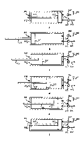
[0021] FIGS. 4a through 4f are simplified views of the cryogenic pump of FIG.
2
illustrating the piston in resting positions during a pumping cycle. FIG. 4a
illustrates the
CA 02882584 2015-02-19
- 9 -
piston at the beginning of an intake stroke. FIG.4b illustrates the piston at
the beginning
of a discharge stroke. FIGS.4c, 4d, 4e and 4f illustrate the piston at the end
of first,
second, third and fourth incremental discharge strokes. At the end of the
fourth discharge
stroke illustrated in FIG.4f the piston is at the same position as in FIG.4a
at the beginning
of the intake stroke.
[0022] FIG. 5 is a flow chart view of a method for operating the cryogenic
pump of
FIG. 2.
[0023] FIG. 6 is a schematic view of a gaseous fuel supply system for an
internal
combustion engine according to a second embodiment.
[0024] FIG. 7 is a schematic view of a gaseous fuel supply system for an
internal
combustion engine according to a third embodiment comprising a heat exchanger
employing an electric heater as a heat source for vaporizing.
[0025] FIG. 8 is a schematic view of a gaseous fuel supply system for an
internal
combustion engine according to a fourth embodiment comprising a heat exchanger
employing a boiler burning boil-off gas as a heat source for vaporizing.
Detailed Description of Preferred Embodiment(s)
[0026] Referring to FIG. 1, there is shown a simplified gaseous fuel supply
system
100 delivering gaseous fuel to internal combustion engine 110. Gaseous fuel is
stored as
a liquid at cryogenic temperatures in storage vessel 120, and is referred to
herein
interchangeably as a cryogenic fluid. Pumping apparatus 130 pumps liquefied
gaseous
fuel from vessel 120 through piping 240 towards heat exchanger 140 through
piping 250
where the fuel undergoes a transition from the liquid to either the gas state
or the
supercritical state. In other embodiments, pumping apparatus 130 and heat
exchanger 140
can be located inside storage vessel 120. In the present embodiment the
pressure and
temperature of the gaseous fuel downstream of heat exchanger 140 are such that
the
CA 02882584 2015-02-19
- 10 -
gaseous fuel is in the gas state, but in other embodiments the pressure and
temperature of
the gaseous fuel are such that the gaseous fuel is in the supercritical state.
Heat
exchangers are also known as vaporizers, as would be known to those familiar
with the
technology. Additionally, as a consequence of delivering more liquefied gas
into piping
250, apparatus 130 pressurizes vaporized gaseous fuel downstream from heat
exchanger
140 in piping 190. A fuel injection system (not shown) fluidly communicates
with piping
190 and introduces (directly or indirectly) vaporized gaseous fuel to one or
more
combustion chambers in internal combustion engine 110. Piping 205 and 210 are
part of
an engine coolant circuit and are in fluid communication with a water jacket
(not shown)
in engine 110 allowing circulation of engine coolant from the water jacket
through heat
exchanger 140 where waste heat from combustion is employed to vaporize the
liquefied
gaseous fuel. With regard to heat exchanger 140, the engine coolant is a
working fluid
and the gaseous fuel from pumping apparatus 130 is a process fluid. The
working fluid
does work on the process fluid to change its state. As used herein, engine
coolant
temperature is equivalent to working fluid temperature, and gaseous fuel
temperature is
equivalent to process fluid temperature.
[0027] Electronic controller 150 communicates with engine 110 to receive
status
signals from sensors employed in internal combustion engines and to control
actuators
such as those found in fuel injectors.
Temperature sensor 160 sends signals
representative of the temperature of engine coolant in piping 205 to
controller 150.
Alternatively, or additionally, a temperature sensor (not shown) can be
employed to send
signals to the controller representative of the temperature of engine coolant
in piping 210.
Temperature sensor 170 sends signals representative of the temperature of
vaporized
gaseous fuel in piping 190, and pressure sensor 180 sends signals
representative of the
pressure of vaporized gaseous fuel in piping 190 to controller 150.
[0028] Pumping apparatus 130 comprises a positive displacement pump that
allows
for a variable displacement of gaseous fuel during compression strokes of the
pump.
CA 02882584 2015-02-19
- 1 1 -
Positive displacement pumps of the types that are mechanically, hydraulically
and
electrically actuated can be employed. Command and status signals are
transmitted over
control line 230 such that controller 150 commands pumping apparatus 130 to
pump.
Alternatively, or additionally, mechanical drive 220 from engine 110, such as
a power
take off and the like, is employed to actuate apparatus 130 to pump liquefied
gaseous
fuel.
[0029]
Referring now to FIG. 2 there is shown a partial view of pumping apparatus
130 including reciprocating-piston pump 300 shown in simplified form as would
be
known by those familiar with the technology. Piston rod 320 is connected with
piston
310 and is driven by known mechanically, hydraulically or electrically
actuated
mechanisms to reciprocate the piston within cylinder 330 between cylinder
heads 340 and
350. Proximate cylinder head 340 is near fuel inlet 345 for cylinder 330, and
in this
embodiment comprises the fuel inlet, and distal cylinder head 350 comprises an
opening
for piston rod 320. Inlet check valve 360 allows liquefied gaseous fuel to
enter cylinder
330 from storage vessel 120 during an intake stroke of pump 300 when piston
310 moves
away from cylinder head 340. Although not illustrated in FIG. 2, inlet check
valve 360
can be located in fuel inlet 345 in other embodiments. Outlet check valve 370
allows
gaseous fuel to exit cylinder 330 during a discharge stroke of pump 300 when
piston 310
moves towards cylinder head 340. Intake strokes of pump 300 are also known as
suction
strokes or retraction strokes, and discharge strokes are also known as
compression strokes
or extension strokes, as would be known by those familiar with the technology.
Inlet
check valve 360 is closed during the discharge stroke and outlet check valve
370 is
closed during the intake stroke. Although outlet check valve 370 is in fluid
communication with a conduit through cylinder head 340, the conduit is not
required to
pass through the cylinder head and in other embodiments the conduit can pass
through a
wall of cylinder 330 near the cylinder head. Pump 300 has a maximum
displacement
volume of VD,MAX, which is the volume between piston 310 and cylinder head 340
when
the piston is fully retracted to cylinder head 350 after the intake stroke, as
illustrated in
CA 02882584 2015-02-19
¨ 12 -
FIG. 2. The length piston 310 travels during a complete intake stroke is Ls.
During a
complete discharge stroke pump 300 discharges a volume of gaseous fuel equal
to
displacement volume VD,MAX by fully extending piston 310 to cylinder head 340,
as is
shown in FIG. 3. The length piston 310 travels during a complete discharge
stroke is also
Lfs=
[0030] Heat exchanger 140 comprises heat exchange conduit 400 through which
gaseous fuel passes from pump 300 towards engine 110. Conduit 400 represents
the
effective heat exchange region where heat is transferred between engine
coolant, passing
through the heat exchanger from supply piping 205 to return piping 210, and
gaseous
fuel. The volume of gaseous fuel within conduit 400 is defined as VHE, and is
also
referred to as the effective heat exchange volume in this specification.
During normal
engine operating conditions, the temperature of the gaseous fuel exiting
conduit 400 is
elevated above a predetermined minimum value. A temperature differential
between
engine coolant in piping 205 and gaseous fuel entering conduit 400 allows
sufficient heat
transfer to occur to vaporize the gaseous fuel discharged from heat exchanger
140 and
raise its temperature above the predetermined minimum value in conduit 190.
The
temperature differential between engine coolant and liquefied gaseous fuel in
all engine
operating conditions is substantially determined by the temperature of engine
coolant in
piping 205 since the temperature of liquefied gaseous fuel is at or near its
boiling point in
vessel 120 and piping 250.
[0031] During
certain engine operating conditions of engine 110, the temperature
differential between engine coolant and liquefied natural gas is insufficient
to elevate the
temperature of vaporized gaseous fuel in conduit 190 above the predetermined
minimum
value. One such condition occurs during engine cold start when the temperature
of
engine coolant is equal or near to ambient temperature. In this situation not
enough heat
has been transferred from the engine coolant to the volume of gaseous fuel
leaving heat
exchanger 140 during the discharge stroke to elevate its temperature above the
CA 02882584 2015-02-19
- 13 -
predetermined minimum value. To increase gaseous fuel temperature in conduit
190 heat
transfer to the volume of gaseous fuel discharged from heat exchanger 140 for
each pump
stroke must be increased. Increasing the temperature differential will
increase heat
transfer; however, since engine coolant temperature cannot be immediately
increased
another technique must be employed. Increasing the effective residence time of
the
volume of gaseous fuel discharged from heat exchanger during each discharge
stroke of
pump 300 also increases heat transfer to the gaseous fuel. The heat
transferred into the
gaseous fuel is determined by the heat transfer rate (which is a function of
the
temperature differential between engine coolant temperature and liquefied
gaseous fuel
temperature) and the amount of time the gaseous fuel spends in the effective
heat
exchange region (residence time) of heat exchanger 140.
[00321 Referring to FIGS. 4a through 4f a pump cycle for pump 300 is now
described
that increases the effective residence time of cryogenic fluid in heat
exchanger 140 by
performing multiple incremental discharge strokes for each complete intake
stroke of
piston 310. In FIG. 4a, piston 310 is adjacent proximate cylinder head 340 and
is about
to begin the intake stroke during which cryogenic fluid is drawn in through
inlet check
valve 360 as the piston travels towards distal cylinder head 350. After
completing the
intake stroke piston 310 is adjacent cylinder head 350, as illustrated in FIG.
4b, where the
piston is about to begin discharging cryogenic fluid through outlet check
valve 370.
Instead of the piston continuously travelling until it reaches cylinder head
340, the piston
is advanced towards cylinder head 340 in discrete steps by repeatedly moving
the piston
towards cylinder head 340 in increments and stopping between the increments.
FIGS. 4c
through 4f illustrate piston 310 at rest after having completed first, second,
third and
fourth incremental discharge strokes respectively. This technique can also be
called
=
pulsed discharging referring to the pulsed nature of the pressure of a
hydraulic fluid that
is employed to actuate piston 310 in certain embodiments. For example, in FIG.
4c piston
310 is shown stationary after having moved from the position illustrated in
FIG. 4b. After
a predetermined time interval (that is, the rest period) piston 310 begins
another pulsed
CA 02882584 2015-02-19
- 14 -
discharge stroke and moves to the location illustrated in FIG. 4d, and again
waits for the
predetermined time interval until moving to the location illustrated in FIG.
4e, and so on
until the piston reaches cylinder head 340. The length of each discharge
stroke, and the
volume of fluid discharged, can be the same for each incremental discharge
stroke, or
they can be different. Similarly, the amount of time piston 310 is stopped
between
incremental discharge strokes can be the same, or it can be different. In the
illustrated
embodiment of FIGS. 4a through 4f, a complete pump cycle comprises one
complete
intake stroke and four incremental discharge strokes. In general, there can be
two or more
incremental discharge strokes for each complete intake stroke. In other
embodiments,
instead of piston 310 coming to rest between incremental discharge strokes, it
can slow
down such that the velocity of the piston between incremental discharge
strokes is greater
than zero and less than the velocity of the piston during incremental
discharge strokes.
[0033] Referring now to FIG. 5, a method of operating pumping apparatus 130
(seen
in FIG. 1) is now described. In step 380 one of the process fluid temperature
and the
working fluid temperature is monitored to determine whether the residence time
of the
gaseous fuel inside the heat exchanger needs to be increased. The process
fluid is the
gaseous fuel, and is typically measured downstream from heat exchanger 140,
and the
working fluid is the heat exchange fluid of the heat exchanger, which in an
exemplary
embodiment is engine coolant from engine 110. The process fluid temperature or
the
working fluid temperature is compared with the predetermined minimum value in
step
385 to determine when it is below this value, and when it is below the
predetermined
minimum value the technique of incremental discharge strokes is performed in
steps 390
and 395. In step 390, piston 310 is retracted during an intake from proximate
cylinder
340 near fuel inlet check valve 360 to distal cylinder head 350. In step 395,
piston 310 is
extended in a plurality of incremental discharge strokes until the piston
travels from distal
cylinder head 350 to proximate cylinder head 340. Steps 390 and 395 can be
performed
repeatedly until the process fluid temperature and the working fluid
temperature is above
the predetermined minimum value.
CA 02882584 2015-02-19
- 15 -
[0034] By employing a plurality of incremental discharge strokes for pump 300
the
residence time of cryogenic fluid in heat exchanger 140 is increased allowing
more heat
to transfer to the cryogenic fluid increasing the average temperature of the
fluid both in
the heat exchanger and downstream thereof. The likelihood of engine coolant
freezing is
reduced since the average temperature of the cryogenic fluid in the heat
exchanger has
increased. The size of heat exchanger 140 can be reduced, especially in low
pressure
applications where the effective heat exchange volume VHE is conventionally
several
times the size of displacement volume VD,MAX of cryogenic pump 300 to allow
engine
110 to cold start fuelling with gaseous fuel immediately. Previously, heat
exchange
volume VHE was sized such that gaseous fuel temperature downstream of heat
exchanger
140 was maintained above the predetermined value while pump 300 performed a
complete discharge stroke where piston 310 travelled continuously full stroke
length Lfs.
When incremental discharge strokes are performed, heat exchange volume VHE can
be
less than it would be if incremental discharge strokes are not performed. A
smaller heat
exchanger is less expensive and can be integrated into off-engine systems with
greater
flexibility.
[0035] The volumetric efficiency of the incremental stroke technique taught
herein is
improved compared to the partial stroke technique of the '495 patent
hereinbefore
described. The incremental stroke technique requires a fewer number of intake
strokes,
compared to the partial stroke technique, to pump equivalent volumes of
process fluid.
For example, if the partial stroke technique pumps half the maximum
displacement
volume VD,MAX of pump 300 for each partial stroke, then the partial stroke
technique
requires two intake and discharge strokes for each intake and complete
discharge stroke
of the incremental discharge stroke technique to pump approximately the same
volume of
process fluid. Each partial or full intake stroke requires inlet check valve
360 to open
from a closed position. Each time the inlet check valve opens a small amount
of
cryogenic fluid flashes as it fills the volume between piston 310 and cylinder
head 340.
This volume comprises a dead space volume and the volume due to piston 310
moving
CA 02882584 2015-02-19
- 16 -
away from the inlet check valve at the beginning of the intake stroke. The
dead space
volume is that volume between piston 310 and cylinder head 340 when the piston
is full
extended towards the cylinder head, and exists primarily due to manufacturing
tolerances.
The cryogenic fluid flashes due to a pressure drop across the inlet check
valve and when
the cryogenic fluid absorbs heat from piston 310, which heats up due to the
reciprocating
motion within cylinder 330. The incremental stroke technique therefore flashes
a smaller
amount of cryogenic liquid, compared to the partial stroke technique, since
the
incremental stroke technique requires less intake strokes to pump the same
amount of
process fluid. Flashing of cryogenic fluid in cylinder 330 reduces the
effective
displacement volume of pump 300 since the flashed fluid needs to be re-
condensed
during the discharge stroke before pressure within cylinder 330 can begin to
significantly
increase to open outlet check valve 370. Since the partial stroke technique
flashes more
cryogenic fluid compared to the incremental stroke technique when piston 310
travels a
complete discharge stroke length (LFs), then the partial stroke technique
pumps less
process fluid. It follows that by decreasing the amount of cryogenic fluid
that flashes in
pump 300 (by decreasing the number of times inlet check valve 360 opens) the
fewer the
number of pump cycles are required to pump a predetermined amount of fuel,
thereby
increasing volumetric efficiency of the pump. In the incremental stroke
technique,
volumetric efficiency can decrease if gaseous fuel in cylinder 330 blows-by a
seal (not
shown) that fluidly seals the piston with the cylinder, after piston 310 comes
to a stop at
the end of an incremental discharge stroke, requiring the pressure in the
cylinder to be
built up again on the next incremental discharge stroke. It is preferred that
blow-by gas be
reduced.
100361 Other embodiments of gaseous fuel supply systems will now be described
with respect to FIGS. 6, 7 and 8, on which the incremental stroke technique
described
herein can be performed. There can be other gaseous fuel supply systems, known
to those
familiar with the technology, on which the incremental stroke technique can be
performed.
CA 02882584 2015-02-19
- 17 -
[0037] Referring now to FIG. 6, gaseous fuel supply system 200 is shown in
schematic form according to a second embodiment that is similar to the
embodiment of
FIG. 1 and like parts have like reference numerals and may not be described in
detail, if
at all. Pumping apparatus 130 comprises reciprocating-piston, positive
displacement
pump 301 actuated by hydraulic circuit 500. Hydraulic pump 510 pumps hydraulic
fluid
from reservoir 520 through flow control valve 530. Hydraulic pump 510 is
driven by
engine 110 over mechanical linkage 220 such that its speed is directly related
to the speed
of engine 110. Valve 530 is actuated by controller 150 over line 230 to switch
the flow
direction of hydraulic fluid into and out of pump 301, and to divert flow from
pump 301
altogether. The flow direction of hydraulic fluid in piping 540 and 550 with
respect to
pump 301 is alternated between intake and discharge strokes, as will be
explained in
more detail below. The flow of hydraulic fluid is diverted away from the pump
back to
reservoir 520 when pump 301 is suspended or stopped. The flow rate of
hydraulic fluid
in circuit 500 is directly related to the speed of engine 110. Similarly, the
flow rate of
gaseous fuel pumped by pump 301 when the pump is continuously pumping is also
directly related to the speed of engine 110 since it is driven by hydraulic
circuit 500. It is
not possible to decrease the speed of pump 301 at any particular engine speed
to increase
the residence time of gaseous fuel in heat exchanger 140 unless a transmission
is
employed between engine 110 and hydraulic pump 510, which would increase the
cost of
fuel system 200 and effect gaseous fuel flow rate. Hydraulic circuit 500 can
be operated
to command pump 301 to perform the incremental discharge technique described
with
respect to FIGS. 4a through 4f.
[0038] Referring now to FIG. 7, gaseous fuel supply system 700 is shown
according
to a third embodiment that is similar to the embodiment of FIG. 1 and like
parts have like
reference numerals and may not be described in detail, if at all. Heat
exchanger 141
comprises an electric heater (not shown) for generating heat to vaporize
liquefied gaseous
fuel received from pumping apparatus 130. The amount of heat generated by the
electric
heater is controlled by controller 150 over line 710, and can be increased or
decreased
CA 02882584 2015-02-19
- 18 -
separately from changes in the speed of engine 110. Temperature sensor 720
emits
signals to controller 150 representative of a temperature of a heat exchange
region inside
the heat exchanger, for example representative of a temperature of the
electric heater. It
is advantageous to perform the technique of incremental discharge stroking
described
previously with pumping apparatus 130 in the present embodiment, since the
heat
generated from the electric heater cannot be immediately increased or it may
not be
desired to increase energy of consumption of the electric heater. In some
applications it
is advantageous to combine the electric heater in heat exchanger 141 and the
employment
of engine coolant in heat exchanger 140 into a single heat exchanging
apparatus.
[0039] Referring now to FIG. 8, gaseous fuel supply system 800 is shown
according
to a fourth embodiment that is similar to the embodiment of FIG. 1 and like
parts have
like reference numerals and may not be described in detail, if at all. Heat
exchanger 142
comprises a boiler (not shown) that burns at least one of boil-off gas,
received from
storage vessel 120 over piping 830, and liquefied gaseous fuel from storage
vessel 120
for generating heat to vaporize liquefied gaseous fuel. The amount of heat
generated by
the boiler is controlled by controller 150 over line 810, and can be increased
or decreased
separately from changes in the speed of engine 110. Temperature sensor 820
emits
signals to controller 150 representative of a temperature of a heat exchange
region inside
the heat exchanger, for example representative of a temperature generated by
the boiler.
It is advantageous to perform the technique of incremental discharge stroking
described
previously with pumping apparatus 130 in the present embodiment, since the
heat
generated from the boiler cannot be immediately increased or it may not be
desired to
increase boil-off consumption of the boiler. In some applications it is
advantageous to
combine the boiler in heat exchanger 142 and the employment of engine coolant
in heat
exchanger 140 into a single heat exchanging apparatus.
[0040] While particular elements, embodiments and applications of the present
invention have been shown and described, it will be understood, that the
invention is not
CA 02882584 2015-02-19
- 19 -
limited thereto since modifications can be made by those skilled in the art
without
departing from the scope of the present disclosure, particularly in light of
the foregoing
teachings.