Language selection

Search

Patent 2883327 Summary

Third-party information liability

Some of the information on this Web page has been provided by external sources. The Government of Canada is not responsible for the accuracy, reliability or currency of the information supplied by external sources. Users wishing to rely upon this information should consult directly with the source of the information. Content provided by external sources is not subject to official languages, privacy and accessibility requirements.

Claims and Abstract availability

Any discrepancies in the text and image of the Claims and Abstract are due to differing posting times. Text of the Claims and Abstract are posted:

  • At the time the application is open to public inspection;
  • At the time of issue of the patent (grant).
(12) Patent: (11) CA 2883327
(54) English Title: INTERIOR LADDER RACK
(54) French Title: SUPPORT INTERIEUR POUR ECHELLE
Status: Granted and Issued
Bibliographic Data
(51) International Patent Classification (IPC):
  • B60R 11/00 (2006.01)
  • B60R 11/06 (2006.01)
(72) Inventors :
  • SAUTTER, ROBERT H., JR. (United States of America)
(73) Owners :
  • ADRIAN STEEL COMPANY
(71) Applicants :
  • ADRIAN STEEL COMPANY (United States of America)
(74) Agent: SMART & BIGGAR LP
(74) Associate agent:
(45) Issued: 2021-06-15
(22) Filed Date: 2015-03-02
(41) Open to Public Inspection: 2015-09-04
Examination requested: 2019-11-19
Availability of licence: N/A
Dedicated to the Public: N/A
(25) Language of filing: English

Patent Cooperation Treaty (PCT): No

(30) Application Priority Data:
Application No. Country/Territory Date
61/947,734 (United States of America) 2014-03-04

Abstracts

English Abstract

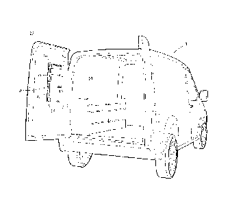
A mounting system for detachably storing ladders comprising at least one elongate member with a length and opposed first and second ends. The system also includes a ledge adapted to be movable along the length of the elongate member. A securing latch is provided which is adapted to be movable along the length of the elongate member. The securing latch is pivotally carried on the elongate member. The securing latch can have a gas spring with a body pivotally attached to the elongate member and a rod pivotally attached to the latch. The latch has a profile complimentary to a surface of said ladder.


French Abstract

Un système de montage pour stocker de manière amovible des échelles comprend au moins un élément allongé ayant une longueur et des première et seconde extrémités opposées. Le système comprend également un rebord conçu pour être mobile le long de la longueur de lélément allongé. Un verrou de fixation est conçu pour être mobile le long de la longueur de lélément allongé. Le verrou de fixation est porté de manière pivotante sur lélément allongé. Le verrou de fixation peut avoir un ressort à gaz ayant un corps fixé de manière pivotante à lélément allongé et une tige fixée de manière pivotante au verrou. Le verrou a un profil complémentaire à une surface de ladite échelle.

Claims

Note: Claims are shown in the official language in which they were submitted.


5
CLAIMS
1. A mounting system for detachably storing ladders, comprising:
at least one elongate member vertically mountable to an interior wall of a
vehicle;
a ledge extending outwardly from the elongate member and adapted to be movable
along
and securable to the elongate member; and
= a latch adapted to be movable and securable along the elongate member,
the latch being
pivotably secured to the elongate member and including a rear leg portion
extending downwardly
from a central portion to facilitate engagement with a ladder to cause
rotation of the latch, and a
forward leg portion extending downwardly from the central portion to engage a
forward top
portion of the ladder to secure the ladder on the mounting system.=
2. The system of claim 1, in which the latch is operably engaged with a gas
spring secured to
the elongate member to assist in rotating an upper end of the ladder outwardly
upon unlatching of
the latch from the ladder.
CA 2883327 2019-11-19

Description

Note: Descriptions are shown in the official language in which they were submitted.


CA 02883327 2015-03-02
INTERIOR LADDER RACK
FIELD OF THE DISCLOSURE
[0001] This disclosure relates to vehicle racks that facilitate loading and
unloading of a
ladder, and more particularly to a ladder rack that is mounted within the
interior of a vehicle.
BACKGROUND OF THE DISCLOSURE
[0002] Transporting ladders in vehicles has been a persistent issue in the
field. It is known to
transport ladders on vehicles when the ladders are mounted on the outside of
the vehicles.
Oftentimes, there are racks and carriers made for this purpose that can be
mounted to the outside
or roof of the vehicle. However, there are instances where it is desired to
transport ladders in the
interior of the vehicle. While it is an easy matter to stack ladders in the
interior space of a
vehicle, it is necessary to carry the ladders in the interior of the vehicle
such that they are secured
into place and do not move responsive to the movement of the vehicle, and that
are easily
removed and remounted into stored location in the vehicle.
SUMMARY
[0003] In one embodiment, there is disclosed a system to carry ladders in a
vehicle interior,
such as a van, that permits storage of ladders in a variety of locations to
maximize space usage,
wherein the ladders can be stored on the vehicle walls, or doors or even
partitions within the
interior of the vehicle. The system includes an elongate member vertically
mountable to an
interior wall or partition of a vehicle, a ledge for supporting a bottom rung
of a ladder, and a
latch pivotably secured to the elongate member and adapted to engage a top
portion of a ladder.
The latch can have a rear leg portion extending downwardly from a central
portion to engage a
rear top portion of a ladder, and a forward leg portion extending downwardly
from the central
portion to engage a forward top portion of a ladder. One or both of the ledge
and latch can be
adapted to be movable and securable along the elongate member to accommodate
ladders of
different sizes.
1

CA 02883327 2015-03-02
BRIEF DESCRIPTION OF THE DRAWINGS
[0004] Figure 1 is a perspective view of a vehicle interior with a ladder
stored in the vehicle
in accordance with one embodiment of the mounting system of this disclosure.
[0005] Figure 2 is a perspective view of the vehicle interior of Figure 1
showing the
mounting systems without the ladder.
[0006] Figure 3 is an elevated side view of a ladder being placed on the
mounting system of
Figure 2.
[0007] Figure 4 is an elevational side view of the ladder of Figure 3
secured on the mounting
system.
DETAILED DESCRIPTION
R)008] Turning now to the drawings wherein like numbers refer to like
structures, Figure 1 is
a sectional view of the interior 10 of vehicle 12 showing one orientation of a
rack or ladder
storage system 14. The ladder 18 shown in Figure 1 can be any of a variety of
sizes, and shapes.
The ladder storage system can be located on an interior vehicle wall, such as
on the interior side
of the vehicle door 27 in a vertical orientation.
[0009] Figure 2 shows the interior of vehicle 12 wherein the ladder is
removed revealing the
mounting systems 14 for ladder 18. The mounting system 14 is comprised of
vertically oriented
elongate member 34, having a first end 36, and opposite second end 38 which
define a height.
The vertical member 34 has opposite sidewalls 42 and 44 in substantially
parallel orientation to
each other and separated by a recessed front face 46 to define a guide. A
support ledge 50 may
be equipped with flanges complimentary to the orientation of the sidewalls
such that support
ledge 50 may be adjustably slidably positioned along the height 40 of the
vertical member 34.
Securing latch 52 is provided in the mounting system and is also of similar
profile as ledge 50
such that it is slidably adjustable along the length of the guide. As seen in
Figure 3, the securing
latch 52 is pivotally affixed on a flange 55 at pivot 56 and extends outwardly
away from the
recessed front face 46. Latch 52 has a profiled surface 58 that conforms to a
surface 60 of the
2

3
ladder, and a gas spring 62 having a cylinder 64 pivotally carried by flange
66 extending
outwardly away from recessed front face 46 and equipped with a rod 68.
[0010] The gas spring is used to lock latch 52 in place to secure ladder 18
in position. Rod
68 is attached to the latch and when the latch is moved into the secure
position shown in Figure
4, an end of rod 68 travels toward pivot 71 generating a constant spring force
to clamp ladder 18
in place. When latch 52 is moved to its open or un-latched position, the end
of rod 68 moves to
release the ladder and hold latch 52 open until the ladder is loaded once
again.
[0011] In operation, ledge 50 of ladder 18 is positioned on guide 48 along
the length of the
transverse member and is secured into a desired place. Ladder 18 is positioned
on ledge 50 such
that the ladder rung 70 rests on ledge 50. Ladder 18 is placed on the ledge 50
and then pivoted
into place to interact with latch 52. In particular, a top rearward portion 80
of ladder 18 impinges
on a rear leg portion 82 of latch 52 that extends downwardly from a central
portion 84 of latch 52
causing latch 52 to rotate on pivot 56 when a ladder is positioned on ledge 50
and pushed
forward, and a forward leg portion 86 of latch 52 engages a top forward
portion 88 of ladder 18,
thereby securing ladder 18 on rack 14. To remove ladder 18, latch 52 is
released, ladder 18 is
pivoted outwardly, and then ladder 18 is removed from the ledge 50.
[0012] Because both the ledge 50 and latch 52 are adjustable along a length
of the elongate
member 34, the ladder storage system 14 is fully adjustable to accommodate
different sizes and
different types of step ladders. Both latch 52 and ledge 50 can be coated with
an energy
absorbing material such as a plastisol material to protect ladders from damage
during loading and
unloading. The ladder storage system 14 automatically clamps and holds a
ladder using a gas
spring, allowing a person to hang a ladder on ledge 50 and push the ladder
against the rear leg
portion 82 to cause the ladder to be secured on the system 14.
[0013] The disclosure herein is only one embodiment of the invention. Those
skilled in the
art understand that the words herein are words of description, and not words
of limitation. Many
variations and modifications may be made without departing from the scope of
the disclosure.
The scope of protection being sought is defined by the following claims rather
than the described
embodiments in the foregoing description. The scope of the claims should not
be limited by the
CA 2883327 2019-11-19

4
described embodiments set forth in the examples but should be given the
broadest interpretation
consistent with the description as a whole.
CA 2883327 2019-11-19

Representative Drawing
A single figure which represents the drawing illustrating the invention.
Administrative Status

2024-08-01:As part of the Next Generation Patents (NGP) transition, the Canadian Patents Database (CPD) now contains a more detailed Event History, which replicates the Event Log of our new back-office solution.

Please note that "Inactive:" events refers to events no longer in use in our new back-office solution.

For a clearer understanding of the status of the application/patent presented on this page, the site Disclaimer , as well as the definitions for Patent , Event History , Maintenance Fee  and Payment History  should be consulted.

Event History

Description Date
Inactive: Grant downloaded 2021-06-18
Letter Sent 2021-06-15
Grant by Issuance 2021-06-15
Inactive: Cover page published 2021-06-14
Inactive: Final fee received 2021-04-27
Pre-grant 2021-04-27
Notice of Allowance is Issued 2021-01-14
Letter Sent 2021-01-14
Notice of Allowance is Issued 2021-01-14
Inactive: Approved for allowance (AFA) 2020-12-31
Inactive: QS passed 2020-12-31
Common Representative Appointed 2020-11-07
Letter Sent 2019-11-29
Amendment Received - Voluntary Amendment 2019-11-19
Request for Examination Received 2019-11-19
All Requirements for Examination Determined Compliant 2019-11-19
Request for Examination Requirements Determined Compliant 2019-11-19
Common Representative Appointed 2019-10-30
Change of Address or Method of Correspondence Request Received 2018-01-12
Inactive: Cover page published 2015-09-21
Application Published (Open to Public Inspection) 2015-09-04
Inactive: IPC assigned 2015-03-20
Inactive: First IPC assigned 2015-03-20
Inactive: IPC assigned 2015-03-20
Inactive: Filing certificate - No RFE (bilingual) 2015-03-09
Filing Requirements Determined Compliant 2015-03-09
Letter Sent 2015-03-09
Application Received - Regular National 2015-03-05
Inactive: Pre-classification 2015-03-02
Inactive: QC images - Scanning 2015-03-02

Abandonment History

There is no abandonment history.

Maintenance Fee

The last payment was received on 2021-02-26

Note : If the full payment has not been received on or before the date indicated, a further fee may be required which may be one of the following

  • the reinstatement fee;
  • the late payment fee; or
  • additional fee to reverse deemed expiry.

Please refer to the CIPO Patent Fees web page to see all current fee amounts.

Fee History

Fee Type Anniversary Year Due Date Paid Date
Registration of a document 2015-03-02
Application fee - standard 2015-03-02
MF (application, 2nd anniv.) - standard 02 2017-03-02 2017-02-17
MF (application, 3rd anniv.) - standard 03 2018-03-02 2018-02-23
MF (application, 4th anniv.) - standard 04 2019-03-04 2019-02-25
Request for examination - standard 2020-03-02 2019-11-19
MF (application, 5th anniv.) - standard 05 2020-03-02 2020-02-21
MF (application, 6th anniv.) - standard 06 2021-03-02 2021-02-26
Final fee - standard 2021-05-14 2021-04-27
MF (patent, 7th anniv.) - standard 2022-03-02 2022-02-25
MF (patent, 8th anniv.) - standard 2023-03-02 2023-02-24
MF (patent, 9th anniv.) - standard 2024-03-04 2024-02-23
Owners on Record

Note: Records showing the ownership history in alphabetical order.

Current Owners on Record
ADRIAN STEEL COMPANY
Past Owners on Record
ROBERT H., JR. SAUTTER
Past Owners that do not appear in the "Owners on Record" listing will appear in other documentation within the application.
Documents

To view selected files, please enter reCAPTCHA code :


To view images, click a link in the Document Description column. To download the documents, select one or more checkboxes in the first column and then click the "Download Selected in PDF format (Zip Archive)" or the "Download Selected as Single PDF" button.

List of published and non-published patent-specific documents on the CPD .

If you have any difficulty accessing content, you can call the Client Service Centre at 1-866-997-1936 or send them an e-mail at CIPO Client Service Centre.


Document
Description 
Date
(yyyy-mm-dd) 
Number of pages   Size of Image (KB) 
Description 2019-11-19 4 143
Claims 2019-11-19 1 22
Description 2015-03-02 3 133
Abstract 2015-03-02 1 14
Drawings 2015-03-02 3 53
Claims 2015-03-02 1 20
Representative drawing 2015-08-10 1 11
Cover Page 2015-09-21 2 43
Representative drawing 2021-05-18 1 11
Cover Page 2021-05-18 1 38
Maintenance fee payment 2024-02-23 42 1,727
Filing Certificate 2015-03-09 1 179
Courtesy - Certificate of registration (related document(s)) 2015-03-09 1 103
Reminder of maintenance fee due 2016-11-03 1 112
Courtesy - Acknowledgement of Request for Examination 2019-11-29 1 433
Commissioner's Notice - Application Found Allowable 2021-01-14 1 552
Electronic Grant Certificate 2021-06-15 1 2,527
Request for examination / Amendment / response to report 2019-11-19 8 221
Final fee 2021-04-27 4 110