Note: Descriptions are shown in the official language in which they were submitted.
CA 02883506 2015-02-26
FP13-0446-00
DESCRIPTION
Title of Invention
METHOD FOR MANUFACTURING CATALYST FOR CARBON NANOTUBE
SYNTHESIS
Technical Field
[0001] The present invention relates to a method for manufacturing a catalyst
for
carbon nanotube synthesis.
Background Art
[0002] Carbon nanotubes have been synthesized by using granular carriers
(hereinafter called "particulate carriers"). Carbon nanotubes are synthesized
using
particulate carriers in the following manner. A catalyst for carbon nanotube
synthesis is deposited on particulate carriers. The catalyst for carbon
nanotube
synthesis is then reduced by heating with a reducing gas, such as hydrogen, to
be
fine-grained. In doing so, the granular catalyst for carbon nanotube synthesis
is
supported by the particulate carriers. Subsequently, a source gas for carbon
nano-tubes is flown over the catalyst for carbon nanotube synthesis, whereby
carbon
nanotubes are synthesized.
[0003] In such a method for synthesizing carbon nanotubes, a technique to
deposit
a catalyst for carbon nanotube synthesis on particulate carriers is important.
As
techniques to deposit a catalyst for carbon nanotube synthesis on particulate
carriers,
chemical vapor deposition (CVD) (see Patent Literature 1, for example) and
sputtering (see Non Patent Literature 1, for example) have been known.
Citation List
Patent Literature
[0004] [Patent Literature 1] Publication No. W02009/110591
1
CA 02883506 2015-02-26
FP13-0446-00
Non Patent Literature
[0005] [Non Patent Literature 1] Dong Young Kim, Hisaslai Sugime, Kei
Hasegawa, Toshio Ogawa, Suguru Noda; Fluidized-bed synthesis of
sub-millimeter-long single walled carbon nanotube array; CARBON 50 (2012),
1538 - 1545
Summary of Invention
Technical Problem
[0006] Carbon nanotubes include multi-walled carbon nanotubes (MWCNTs) and
single walled carbon nanotubes (SWCNTs). In terms of enhancing characteristics
of carbon nanotubes, single walled carbon nanotubes are more preferable than
multi-walled carbon nanotubes. In the synthesis of multi-walled carbon
nanotubes,
the size of a catalyst for carbon nanotube synthesis supported by particulate
carriers
may be comparatively large. In contrast, in the synthesis of single walled
carbon
nanotubes, the size of a catalyst for carbon nanotube synthesis supported by
particulate carriers needs to be small.
[0007] In the use of CVD, however, the size of a catalyst for carbon nanotube
synthesis supported by particulate carriers cannot be reduced enough to enable
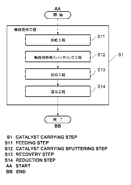
single walled carbon nanotubes to be synthesized. It is thus difficult to
synthesize
single walled carbon nanotubes.
[0008] By contrast, in the use of sputtering, the size of a catalyst for
carbon
nanotube synthesis supported by particulate carriers can be reduced to the
extent that
single walled carbon nanotubes can be synthesized. Single walled carbon
nanotubes can be thus synthesized readily as compared with the case using CVD.
[0009] Conventional sputtering is a method for forming a metal thin film on a
fiat
substrate. A catalyst for carbon nanotube synthesis is thus supported by only
a
single side of each particulate carrier. For this reason, when conventional
2
CA 02883506 2015-02-26
FP13-0446-00
sputtering is used, the film thickness of films on which sputtering is
performed
varies depending on the positions of the surfaces of particulate carriers as
Fig. 5(b)
illustrates, so that carbon nanotubes cannot be produced uniformly. In
addition,
carbon nanotubes cannot be synthesized from the entire surfaces of the
particulate
carriers, resulting in poor production efficiency of carbon nanotubes.
[0010] In view of the above-described disadvantages, it is an object of the
present
invention to provide a method for manufacturing a catalyst for carbon nanotube
synthesis, by which single walled carbon nanotubes can be synthesized and
production efficiency of carbon nanotubes can be enhanced.
Solution to Problem
[0011] As a result of intensive examinations, the inventors of the present
invention
have fundamentally improved a sputtering method and thus have found that a
catalyst for carbon nanotube synthesis can be manufactured with which single
walled carbon nanotubes can be synthesized and production efficiency of carbon
nanotubes can be enhanced.
[0012] Specifically, in one mode, the method for manufacturing a catalyst for
carbon nanotube synthesis according to the present invention includes a
sputtering
step for supporting a catalyst. In this step, sputtering is performed while a
tubular
drum containing particulate carriers is rotated around the axis. A catalyst
for
carbon nanotube synthesis is thus deposited on the particulate carriers. The
manufacturing of a catalyst for carbon nanotube synthesis indicates a process
of
depositing a catalyst for carbon nanotube synthesis on particulate carriers,
and
further indicates a process of reducing the catalyst for carbon nanotube
synthesis
deposited on the particulate carriers by heating to be fine-grained and
causing the
particulate carriers to support the catalyst.
[0013] In the method for manufacturing a catalyst for carbon nanotube
synthesis
3
CA 02883506 2015-02-26
FP13-0446-00
according to the present invention, sputtering can be performed while
particulate
carriers are stirred by rotatint a drum containing the particulate carriers. A
catalyst
for carbon nanotube synthe-is can be thus deposited on the entire surfaces of
the
particulate carriers. By re. cing the catalyst by heating, the fine-grained
catalyst
for carbon nanotube synthesis is supported by the entire surfaces of the
particulate
carriers, which signific. ly enhances productivity of carbon nanotubes.
Furthermore, because the ca alyst for carbon nanotube synthesis is deposited
on the
particulate carriers through puttering, by reducing the resultant particulate
carriers
by heating, the size of th. fine-grained catalyst for carbon nanotube
synthesis
supported by the particulat: carriers is reduced as compared with the case
using
CVD. In such a manner, si igle walled carbon nanotubes can be synthesized.
[0014] In the sputtering s :p for supporting a catalyst in this method, the
drum can
be swung so that one end pi rtion and the other end portion in the axial
direction of
the drum are relatively ve k cally switched. The amount of scattered target
atoms
sputtering from the sputte = g target decreases with distance from the
sputtering
target. Simple rotation of e drum around the axis does not make the amount of
the deposited catalyst for c. lbon nanotube synthesis uniform in the axial
direction of
the drum. On account of =s, the drum is swung in such a manner, so that the
particulate carriers supplied into the drum can be reciprocated in the axial
direction
of the drum. The amount = f the deposited catalyst for carbon nanotube
synthesis
can be thus entirely uniform- d.
[0015] In another mode, a particulate carrier supplying chamber may be
connected
to a vacuum container that ouses the drum, a first opening and closing device
that
opens and closes the space k etween the vacuum container and the particulate
carrier
supplying chamber may 'e provided, and the method may further include a
supplying step of supplyi = g the particulate carrier supplying chamber with
the
4
CA 02883506 2015-02-26
FP13-0446-00
particulate carriers in a state where the first opening and closing device is
closed, the
particulate carrier supplying chamber is brought into a vacuum state, the
first
opening and closing device is opened, the particulate carriers supplied to the
particulate carrier supplying chamber are supplied into the drum, and the
first
opening and closing device is closed to open the particulate carrier supplying
chamber to the atmosphere. In such a manner, the particulate carriers can be
supplied into the drum while the vacuum state of the vacuum container is
maintained. Furthermore, while the first opening and closing device is closed,
the
particulate carrier supplying chamber is opened to the atmosphere. The
particulate
carrier supplying chamber having been in a vacuum state is thus opened to the
atmosphere, allowing the first opening and closing device to open and close.
This
configuration enables the particulate carriers to be supplied to the
particulate carrier
supplying chamber while sputtering is performed in the vacuum chamber.
Sputtering can be thus performed repeatedly without returning the vacuum
container
to the atmospheric state, which enhances productivity.
[0016] The method may further include a recovering step of recovering the
particulate carriers from the drum by inclining the drum. In this step, when
the
drum is inclined, the particulate carriers are discharged from the drum,
whereby the
particulate carriers can be easily recovered. Furthermore, because swing of
the
drum is utilized to incline the drum, the particulate carriers can be
recovered without
adding another function to discharge the particulate carriers from the drum.
This
configuration can simplify a device performing sputtering.
[0017] In another mode, a particulate carrier recovering chamber may be
connected below the vacuum container that houses the drum, a second opening
and
closing device that opens and closes the space between the vacuum container
and
the particulate carrier recovering chamber may be provided, and the method may
5
CA 02883506 2015-02-26
FP13-0446-00
further include a recovering step of recovering the particulate carriers from
the
particulate carrier recovering chamber in which the particulate carrier
recovering
chamber is brought into a vacuum state, the second opening and closing device
is
opened, the drum is inclined to drop the particulate carriers in the drum into
the
particulate carrier recovering chamber, the second opening and closing device
is
closed, and the particulate carrier recovering chamber is opened to the
atmosphere.
In such a manner, the particulate carriers can be recovered from the drum
while the
vacuum state of the vacuum container is maintained. In addition, the second
opening and closing device is closed to open the particulate carrier
recovering
chamber to the atmosphere. The particulate carrier supplying chamber having
been
in a vacuum state is thus opened to the atmosphere, allowing the second
opening
and closing device to open and close. This configuration enables the
particulate
carriers to be recovered from the particulate carrier recovering chamber while
sputtering is performed in the vacuum chamber. Sputtering can be thus
performed
repeatedly without returning the vacuum container to the atmospheric state,
which
enhances productivity.
[0018] Furthermore, in the sputtering step for supporting a catalyst, oxygen
may
be supplied to the vacuum container that houses the drum. When the drum is
rotated around the axis, the particulate carriers may collide with the inner
wall of the
drum, causing the catalyst for carbon nanotube synthesis deposited on the
particulate
carriers to fall off. In consideration of this, sputtering is performed while
oxygen is
supplied into the vacuum container, whereby the catalyst for carbon nanotube
synthesis is oxidized to enhance the joint strength to the grained carriers
through the
oxidization. This configuration can inhibit the catalyst for carbon nanotube
synthesis from falling off from the particulate carriers even when the drum is
rotated
around the axis.
6
CA 02883506 2015-02-26
1?P13-0446-00
[0019] The method may further include a sputtering step for forming catalyst
supporting layers of performing sputtering while the drum containing the
particulate
carriers is rotated around the axis to form catalyst supporting layers for
supporting
the catalyst for carbon nanotube synthesis on the particulate carriers, before
the
sputtering step for supporting a catalyst. The sputtering step for forming
catalyst
supporting layers is thus performed before the sputtering step for supporting
a
catalyst, so that the catalyst for carbon nanotube synthesis can be properly
supported
by the particulate carriers.
[0020] In the sputtering step for forming catalyst supporting layers, oxygen
is
preferably supplied into the vacuum container. As described above, when the
drum
is rotated around the axis, the particulate carriers may collide with the
inner wall of
the drum, causing the catalyst supporting layers formed on the particulate
carriers to
fall off. In consideration of this, sputtering is performed while oxygen is
supplied
into the vacuum container, and thus, the catalyst supporting layers are
oxidized to
enhance the joint strength to the particulate carriers. This configuration can
inhibit
the catalyst supporting layers from falling off from the particulate carriers
even
when the drum is rotated around the axis.
Advantageous Effects of Invention
[0021] According to the present invention, a catalyst for carbon nanotube
synthesis
can be manufactured with which single walled carbon nanotubes can be
synthesized
and production efficiency of carbon nanotubes can be enhanced.
Brief Description of Drawings
[0022] [Fig. 1] Fig. 1 is a flowchart indicating a method for manufacturing a
catalyst for carbon nanotube synthesis according to a first embodiment.
[Fig. 2] Fig. 2 is a longitudinal sectional diagram of a drum sputtering
device.
7
CA 02883506 2015-02-26
FP13-0446-00
[Fig. 3] Fig. 3 is a cross sectional diagram of the drum sputtering device.
[Fig. 4] Figs. 4(a) to 4(c) are elevation schematics illustrating the
positions of the drum.
[Fig. 5] Figs. 5(a) and 5(b) are schematics for illustrating a method for
manufacturing a catalyst for carbon nanotube synthesis using a flat sputtering
device.
[Fig. 6] Fig. 6 is
a schematic for illustrating carbon nanotubes
synthesized from the catalyst for carbon nanotube synthesis manufactured with
a flat
sputtering device.
[Fig. 7] Figs. 7(a) and 7(b) are schematics illustrating a manufacturing
method in the embodiment.
[Fig. 8] Fig. 8 is a schematic for illustrating carbon nanotubes
synthesized from the catalyst for carbon nanotube synthesis manufactured by
the
manufacturing method in the embodiment.
[Fig. 91 Fig. 9 is a flowchart indicating a method for manufacturing a
catalyst for carbon nanotube synthesis according to a second embodiment.
[Fig. 10] Fig. 10 is a diagram illustrating a quartz reactor.
[Fig. 11] Figs. 11(a) to 11(d) are photographs of beads.
[Fig. 12] Fig. 12 is a sectional SEM image of a bead.
[Fig. 13] Figs. 13(a) and 13(b) are sectional SEM images of beads.
[Fig. 14] Fig. 14 is a Raman spectrum of carbon nanotubes in an
example.
Description of Embodiments
[0023] Preferred embodiments of a method for manufacturing a catalyst for
carbon
nanotube synthesis according to the present invention are described in detail
below
with reference to the accompanying drawings. In all of the drawings, like
8
CA 02883506 2015-02-26
FP13-0446-00
numerals refer to like or equivalent components.
[0024] [First Embodiment]
In the method for manufacturing a catalyst for carbon nanotube synthesis
according to the present embodiment, a catalyst for carbon nanotube synthesis
is
deposited on (supported by) particulate carriers by sputtering to manufacture
the
catalyst for carbon nanotube synthesis.
[0025] Fig. 1 is a flowchart indicating a method for manufacturing a catalyst
for
carbon nanotube synthesis according to the first embodiment. As Fig. 1
illustrates,
the method for manufacturing a catalyst for carbon nanotube synthesis
according to
the present embodiment includes a catalyst supporting step (Si) in which a
catalyst
for carbon nanotube synthesis is deposited on particulate carriers on which
catalyst
supporting layers are formed.
[0026] The particulate carriers are configured with granular heat resistant
beads
having heat resistance. The material of the particulate carriers preferably
includes
one or more elements selected from the group consisting of Si, Al, Mg, Zr, Ti,
0, N,
C, Mo, Ta, and W. Specific examples of the material include oxides such as
Si02,
A1203, and MgO, nitrides such as SiN4 and AIN, and carbides such as SiC. The
material may also include complex oxides such as A1203-Si02.
[0027] The catalyst for carbon nanotube synthesis is preferably a metal
typically
used in the synthesis of carbon nanotubes and favorably includes one or more
elements selected from Ti, Ta, V, Cr, Fe, Co, Ni, W, and Au. Among these, Fe,
Co,
and Ni each having a large solid soluble amount with carbon are particularly
preferable.
[0028] The catalyst supporting layers including one or more elements selected
from Si, Al, Mg, 0, C, Mo, and N are favorable. Among these, forms in oxides
such as SiP2, A1202, and MgO, nitrides such as Si3N4 and AIN, and carbides
such as
9
CA 02883506 2015-02-26
FP13-0446-00
SiC are favorable. The catalyst supporting layers may also be a complex oxide
such as A1203-Si02.
[0029] [Drum Sputtering Device]
A drum sputtering device used in the catalyst supporting step (Si) will be
described.
[0030] Fig. 2 is a longitudinal sectional diagram of a drum sputtering device.
Fig.
3 is a cross sectional diagram of the drum sputtering device. As Figs. 2 and 3
illustrate, this drum sputtering device 1 includes a vacuum container 2 in
which
sputtering is performed, a particulate carrier supplying chamber 3 that is
connected
to the vacuum container 2 and is configured to supply particulate carriers
into the
vacuum container 2, and a particulate carrier recovering chamber 4 that is
connected
to the vacuum container 2 and is configured to recover the particulate
carriers from
the vacuum container 2. An upper communication opening 5 that communicates
between the vacuum container 2 and the particulate carrier supplying chamber 3
is
formed at a position between the vacuum container 2 and the particulate
carrier
supplying chamber 3. A lower communication opening 6 that communicates
between the vacuum container 2 and the particulate carrier recovering chamber
4 is
formed at a position between the vacuum container 2 and the particulate
carrier
recovering chamber 4.
[0031] The vacuum container 2 is provided with a main hatch 7 for opening and
closing the vacuum container 2. The vacuum container 2 is also connected to a
vacuum pump 8 that sucks the air in the vacuum container 2 into a vacuum and a
leak valve 9 for supplying air into the vacuum container 2 having been in a
vacuum
state. With this configuration, the inside of the vacuum container 2 can be
brought
into a vacuum state by closing the main hatch 7 and sucking the air in the
vacuum
container 2 into a vacuum by the vacuum pump 8. Air is supplied through the
leak
CA 02883506 2015-02-26
FP13-0446-00
valve 9 into the vacuum container 2 having been in a vacuum state. The vacuum
container 2 is then returned to the atmospheric state, allowing the main hatch
7 to
open and close.
[0032] A drum 10 that is configured to contain particulate carriers is
arranged
inside the vacuum container 2.
[0033] The drum 10 has a tubular shape with which particulate carriers can be
contained therein and is arranged so that the central axis (hereinafter simply
called
the "axis") of the drum 10 is oriented to the horizontal direction. The shape
of the
drum 10 is not particularly limited to a tubular shape and may be, for
example, a
cylindrical shape or a square tubular shape. The inner surface shape of the
drum
10 is also not particularly limited and may be, for example, circular or
polygonal in
cross section. A member such as a stirring plate that stirs the particulate
carriers
may also be attached to the inner surface of the drum 10. Both end portions
10a of
the drum 10 in the axial direction are constricted (reduced in the diameter)
into a
funnel shape so as not to drop off the contained particulate carriers
therefrom. An
opening 10b that is configured to supply particulate carriers into the drum 10
is
formed at one end face 10c in the axial direction of the dn.= 10. The other
end
face 10d that opposes the opening 10b in the axial direction of the drum 10
may or
may not be opened.
[0034] The drum 10 is pivotally supported to be rotatable around the axis and
also
pivotally supported to be vertically tillable with a substantially L-shaped
supporting
arm 11 that extends from the side wall of the vacuum container 2. The drum
sputtering device 1 includes, outside the vacuum container 2, a drive motor 12
for
rotation that rotationally drives the drum 10 around the axis and a drive
motor 13 for
swing that swingingly drives the drum 10 to tilt vertically.
[0035] Specifically, the supporting arm 11 includes a base end arm portion lla
that
11
CA 02883506 2015-02-26
FP13-0446-00
perpendicularly extends from the side wall of the vacuum container 2 and a
leading
end arm portion 1 lb that is bended at the tip of the base end arm portion 11
a at a
right angle. The base end arm portion 1 1 a is pivotally supported so as to be
rotatable around the axis of the base end arm portion 1 1 a against the vacuum
container 2.
[0036] The base end arm portion 1 la is directly or indirectly engaged with
the
drive shaft of the drive motor 13 for swing so that the axis of the drive
shaft of the
drive motor 13 for swing is arranged in parallel with the axis of the base end
arm
portion ha. The leading end arm portion lib extends in the direction
corresponding to the axis of the drum 10, and its tip is inserted into the
drum 10.
[0037] The base end arm portion 11 a is coupled to a circular first gear
member 14
with a bearing, such as a ball bearing, interposed therebetween. With this
configuration, the base end arm portion 11 a and the first gear member 14 are
coupled to be mutually rotatable in a direction around the axis of the base
end arm
portion ha. The drive shaft of the drive motor 12 for rotation is directly or
indirectly engaged with the first gear member 14 so that the axis of the drive
shaft of
the drive motor 12 for rotation is arranged in parallel with the axis of the
base end
arm portion lla.
[0038] The leading end arm portion 1 lb is coupled to a circular second gear
member 15 with a bearing, such as a ball bearing, interposed therebetween.
With
this configuration, the leading end arm portion 11 b and the second gear
member 15
are coupled to be mutually rotatable in a direction around the axis of the
leading end
arm portion 11b. The second gear member 15 is fixed at the other end face 10d
of
the drum 10 so that the axis of the drum 10 corresponds to the axis of the
leading
end arm portion 11b.
[0039] Bevel gears are formed in the first gear member 14 and the second gear
12
CA 02883506 2015-02-26
FP13-0446-00
member 15, respectively, the bevel gears transmitting rotation between the two
shafts that are orthogonal to each other. The first gear member 14 is engaged
with
the second gear member 15 using these bevel gears.
[0040] With this configuration, when the drive shaft of the drive motor 12 for
rotation is rotationally driven, this rotational driving is transmitted to the
drum 10
via the first gear member 14 and the second gear member 15. The drum 10 then
rotates around the axis.
[0041] Furthermore, when the drive shaft of the drive motor 13 for swing is
rotationally driven, the base end arm portion Ila rotates in a direction
around the
axis of the base end arm portion 1 1 a. The leading end arm portion lib is
then
tilted so that the connecting point with the base end arm portion ha serves as
the
central axis. Following this movement, the drum 10 is vertically tilted so
that the
connecting point between the base end arm portion ha and the leading end arm
portion llb serves as the central axis. When the rotational direction of the
driving
shaft of the drive motor 13 for swing is reversed during this operation, the
tilting
direction of the drum 10 is vertically reversed. While the drive shaft of the
drive
motor 13 for swing is rotationally driven, the rotational direction of the
drive shaft
of the drive motor 13 for swing is reversed every time the angle of the tilted
drum 10
reaches a given angle. The drum 10 is thus swung so that the one end portion
and
the other end portion in the axial direction are relatively vertically
switched.
[0042] The swing of the drum 10 is described herein in more detail also with
reference to Fig. 4. Figs. 4(a) to 4(c) are elevation schematics illustrating
the
positions of the drum. In Fig. 4, a reference sign A denotes the axis of the
drum 10,
and a reference sign H denotes the horizontal axis passing through the center
of the
drum 10 in the axial direction.
[0043] A horizontal position a (Fig. 4(a)) will be described. In the drum 10
with
13
CA 02883506 2015-02-26
1?P13-0446-00
this position, the axis A and the horizontal axis H overlap, and the one end
portion
10e in the axial direction of the drum 10 and the other end portion 10f in the
axial
direction of the drum 10 become the same in height.
[0044] In this position, when the drive shaft of the drive motor 13 for swing
is
rotationally driven, the drum 10 is tilted so that the one end portion 10e
moves
upward from the horizontal axis H while the other end portion 10f moves
downward
from the horizontal axis H. The axis A of the drum 10 is thus inclined with
respect
to the horizontal axis H, resulting in a first inclined position 13 (Fig.
4(b)) in which
the one end portion 10e is higher than the other end portion 10f.
[0045] Subsequently, the rotational direction of the drive shaft of the drive
motor
13 for swing is reversed, and then, the drive shaft of the drive motor 13 for
swing is
rotationally driven. The drum 10 is then tilted so that the one end portion
10e and
the other end portion 10f move closer to the horizontal axis H. The drum 10 is
thus
returned back to the horizontal position a (Fig. 4(a)). Furthermore, when the
drive
shaft of the drive motor 13 for swing is rotationally driven in the same
rotational
direction, the drum 10 is tilted so that the one end portion 10e moves
downward
from the horizontal axis H while the other end portion 10f moves upward from
the
horizontal axis H. The axis A of the drum 10 is thus inclined with respect to
the
horizontal axis H, resulting in a second inclined position y (Fig. 4(e)) in
which the
one end portion 10e is lower than the other end portion 101.
[0046] Subsequently, the rotational direction of the drive shaft of the drive
motor
13 for swing is reversed, and then, the drive shaft of the drive motor 13 for
swing is
rotationally driven. The drum 10 is then tilted so that the one end portion
10e and
the other end portion 10f move closer to the horizontal axis H. The drum 10 is
thus
returned back to the horizontal position a (Fig. 4(a)).
[0047] In such a manner, the drive shaft of the drive motor 13 for swing is
14
CA 02883506 2015-02-26
FP13-0446-00
rotationally driven, and the rotational direction of the drive shaft of the
drive motor
13 for swing is reversed every time the angle of the tilted drum 10 reaches a
given
angle. The position of the drum 10 is shifted to (1) the horizontal position
a, (2)
the first inclined position 13, (3) the horizontal position a, (4) the second
inclined
position 7, and (5) the horizontal position a, in this order. This cycle from
(1) to
(5) is repeated. With this repetition, the drum 10 swings so that the one end
portion
10e and the other end portion 10f in the axial direction are relatively
vertically
switched.
[0048] A sputtering target 16 is arranged inside the drum 10 having such a
configuration. The sputtering target 16 is formed into a plate of a metal from
which catalyst supporting layers are formed or a metal from which a catalyst
for
carbon nanotube synthesis is formed. The sputtering target 16 is arranged so
as to
be attachable to and detachable from the leading end arm portion llb that is
inserted
into the drum 10. With this configuration, the sputtering target 16 follows
only the
swing of the drum 10 and does not follow the rotation of the drum 10 around
the
axis. The sputtering target 16 may be arranged at any position inside the drum
10.
In terms of efficiently forming the catalyst supporting layers or the catalyst
for
carbon nanotube synthesis on the particulate carriers, the sputtering target
16 is
preferably arranged at the center of the drum 10 in the axial direction.
[0049] A guiding member 19 with a substantially funnel shape that guides the
particulate carriers discharged from the drum 10 into the lower communication
opening 6 is attached to the inside of the vacuum container 2.
[0050] A sputtering gas supplying device 17 that supplies a sputtering gas for
causing the sputtering target 16 to sputter, into the vacuum container 2 and
an
oxygen supplying device 18 that supplies oxygen into the vacuum container 2
are
connected to the vacuum container 2. The sputtering gas supplying device 17
and
CA 02883506 2015-02-26
FP13-0446-00
the oxygen supplying device 18 may be integrally configured. In this
configuration, a sputtering gas and oxygen are supplied into the vacuum
container 2
in a mixed state.
[0051] The sputtering gas may be any gas so long as it is an inert gas that
can
cause the sputtering target 16 to sputter but is preferably argon gas in terms
of
sputtering efficiency.
[0052] The particulate carrier supplying chamber 3 is configured to supply
particulate carriers into the drum 10 and is arranged at the top of the vacuum
container 2.
[0053] A particulate carrier supplying container 21 that stores particulate
carriers is
installed inside the particulate carrier supplying chamber 3. A supply door 22
that
is opened and closed for supplying the particulate carriers to the particulate
carrier
supplying container 21 is attached to the top of the particulate carrier
supplying
chamber 3.
[0054] A supply nozzle 23 for supplying the particulate carriers supplied to
the
particulate carrier supplying container 21 into the drum 10 is attached to the
particulate carrier supplying container 21. The supply nozzle 23 extends from
the
particulate carrier supplying container 21 to the opening 10b of the drum 10
through
the upper communication opening 5. The supply nozzle 23 is hermetically
connected to the upper communication opening 5. The vacuum container 2 is
communicated to the particulate carrier supplying container 21 only through
the
supply nozzle 23.
[0055] A supply mechanism 24 that is inserted into and removed from the supply
nozzle 23 through the particulate carrier supplying container 21 is provided
at the
particulate carrier supplying chamber 3. The supply mechanism 24 is formed
into
a bar shape that vertically extends, and its upper portion passes through the
16
CA 02883506 2015-02-26
FP13-0446-00
particulate carrier supplying chamber 3 and is exposed to the outside of the
particulate carrier supplying chamber 3. The supply mechanism 24 is
hermetically
slidable against the particulate carrier supplying chamber 3 and can be
inserted into
and removed from the supply nozzle 23. With this configuration, when the
supply
mechanism 24 is pulled up, the supply nozzle 23 is opened. The particulate
carriers stored in the particulate carrier supplying container 21 are then
supplied into
the drum 10 through the supply nozzle 23. In contrast, when the supply
mechanism 24 is pushed down, the supply nozzle 23 is closed. The supplying of
the particulate carriers into the drum 10 is then stopped, and the space
between the
particulate carrier supplying chamber 3 and the vacuum container 2 are
hermetically
maintained.
[0056] A vacuum pump 25 that sucks the air in the particulate carrier
supplying
chamber 3 into a vacuum and a leak valve 26 for supplying air into the
particulate
carrier supplying chamber 3 having been in a vacuum state are connected to the
particulate carrier supplying chamber 3. With this configuration, the inside
of the
particulate carrier supplying chamber 3 can be brought into a vacuum state by
closing the supply door 22, inserting the supply mechanism 24 into the supply
nozzle 23, and sucking the air in the particulate carrier supplying chamber 3
into a
vacuum by the vacuum pump 25. In addition, air is supplied through the leak
valve 26 into the particulate carrier supplying chamber 3 having been in a
vacuum
state. The particulate carrier supplying chamber 3 is then returned to the
atmospheric state, allowing the supply door 22 to open and close.
[0057] The particulate carrier recovering chamber 4 is configured to recover
the
particulate carriers discharged from the inside of the drum 10 and is arranged
below
the vacuum container 2 and directly below the opening 10b of the drum 10. A
door
31 for the lower communication opening that hermetically opens and closes the
17
CA 02883506 2015-02-26
FP13-0446-00
lower communication opening 6 communicating between the vacuum container 2
and the particulate carrier recovering chamber 4 is attached to the lower
communication opening 6.
[0058] A particulate carrier recovering container 32 that recovers the
particulate
carriers is installed inside the particulate carrier recovering chamber 4. A
recovery
door 33 that is opened and closed for loading and unloading the particulate
carrier
recovering container 32 is attached to the side face of the particulate
carrier
recovering chamber 4.
[0059] A vacuum pump 34 that sucks the air in the particulate carrier
recovering
chamber 4 into a vacuum and a leak valve 35 for supplying air into the
particulate
carrier recovering chamber 4 having been in a vacuum state are connected to
the
particulate carrier recovering chamber 4. With this configuration, the inside
of the
particulate carrier recovering chamber 4 can be brought into a vacuum state by
closing the door 31 for the lower communication opening and the recovery door
33,
and sucking the air in the particulate carrier recovering chamber 4 into a
vacuum by
the vacuum pump 34. In addition, air is supplied through the leak valve 35
into the
particulate carrier recovering chamber 4 having been in a vacuum state. The
particulate carrier recovering chamber 4 is then returned to the atmospheric
state,
allowing the recovery door 33 to open and close.
[0060] [Catalyst Supporting Step (Si)]
The catalyst supporting step (Si) in the method for manufacturing a
catalyst for carbon nanotube synthesis according to the present embodiment is
described below in more detail.
[0061] In the catalyst supporting step (Si), the drum sputtering device 1 on
which
the sputtering target 16 is installed is prepared. The sputtering target 16 is
formed
from a material from which a catalyst for carbon nanotube synthesis is to be
formed.
18
CA 02883506 2015-02-26
FP13-0446-00
[0062] As Figs. 1 to 3 illustrate, in the catalyst supporting step (Si), a
supplying
step (S11) in which the particulate carriers are supplied into the drum 10 is
performed.
[0063] The average particle diameter of the particulate carriers in the
supplying
step (S11) may be 5 pm or larger. In this case, the average particle diameter
of the
particulate carriers is preferably 20 um or larger and further preferably 100
um or
larger. When the average particle diameter of the particulate carriers is 5 gm
or
larger, the particulate carriers are not likely to be aggregated. In addition,
even
when the drum 10 is rotated, the particulate carriers are allowed to stay near
the
bottom of the drum 10, which can enhance stirring efficiency of the
particulate
carriers. Furthermore, when the average particle diameter of the particulate
carriers is 20 um or larger and further 100 pm or larger, this effect is
further
enhanced. Here, the maximum of the average particle diameter of the
particulate
carriers can be appropriately set to the extent that the particulate carriers
can be
stirred in the drum 10.
[0064] In the supplying step (S11), the supply mechanism 24 is pushed down to
close the supply nozzle 23, and the particulate carriers are supplied from the
supply
door 22 to the particulate carrier supplying container 21. The supply door 22
is
then closed, and the vacuum pump 25 sucks the air in the particulate carrier
supplying chamber 3 into a vacuum. Subsequently, the supply mechanism 24 is
pulled up to open the supply nozzle 23, and the particulate carriers supplied
to the
particulate carrier supplying container 21 are supplied through the supply
nozzle 23
into the drum 10. With this configuration, when the vacuum container 2 is in a
vacuum state, the particulate carriers can be supplied into the drum 10 while
the
vacuum container 2 is kept in the vacuum state. When the supplying step (S11)
is
performed for the first time, and the vacuum container 2 is in the atmospheric
state,
19
CA 02883506 2015-02-26
FP13-0446-00
there is no need for the vacuum pump 25 to suck the air in the particulate
carrier
supplying chamber 3 into a vacuum. After the supplying of the particulate
carriers
into the drum 10 is completed, the supply mechanism 24 is pushed down to close
the
supply nozzle 23. Air is then supplied through the leak valve 26 into the
particulate carrier supplying chamber 3, whereby the particulate carrier
supplying
chamber 3 having been in a vacuum state is opened to the atmosphere. The
particulate carrier supplying chamber 3 is thus prepared for the subsequent
supply of
particulate carriers.
[0065] Subsequently, in the catalyst supporting step (Si), a sputtering step
(S12)
for supporting a catalyst is performed in which the catalyst for carbon
nan.otabe
synthesis is deposited on the particulate carriers supplied into the drum 10.
[0066] In the sputtering step (S12) for supporting a catalyst, the vacuum pump
8
sucks the air in the vacuum container 2 into a vacuum. During this operation,
the
supply mechanism 24 and the door 31 for the lower communication opening are
closed to hermetically maintain the inside of the vacuum container 2. When the
sputtering step (S12) for supporting a catalyst at this time is the second
time or more,
and the inside of the vacuum container 2 is already maintained in a vacuum
state,
there is no need for the vacuum pump 8 to suck the air in the vacuum container
2
into a vacuum. An operation to suck the air in the vacuum container 2 into a
vacuum in the sputtering step (S12) for supporting a catalyst can be performed
concurrently with an operation to open the particulate carrier supplying
chamber 3
to the atmosphere in the supplying step (811). Subsequently, the drum 10 is
rotated
around the axis and also is swung so that the one end portion 10e and the
other end
portion 10f are relatively vertically switched by driving the drive motor 12
for
rotation and the drive motor 13 for swing.
[0067] The rotational speed of the drum 10 is not particularly limited but may
be,
CA 02883506 2015-02-26
FP13-0446-00
for example, from 0.1 rpm or higher and 60.0 rpm or lower. In this case, the
rotational speed of the drum 10 is preferably 0.5 rpm or higher and 30.0 rpm
or
lower and more preferably 1.0 rpm or higher and 20.0 rpm or lower.
[0068] Although the drum 10 favorably has a high rotational speed in respect
of
stirring properties, the drum 10 favorably has a low rotational speed in
respect of
falling off of the catalyst for carbon nanotube synthesis. The upper limit of
the
rotational speed varies depending on the size or the specific gravity of the
particulate
carriers, or the amount of the particulate carriers filling the drum 10, but
is
preferably 60.0 rpm or lower in order to prevent the particulate carriers from
rotating together with the drum 10 and not dropping. The upper limit of the
rotational speed is more preferably 30.0 rpm or lower in order to prevent the
particulate carriers from floating in the drum 10, being deposited on a target
electrode part (not shown), and causing a short circuit. The most preferable
upper
limit of the rotational speed is 20.0 rpm or lower in order to prevent the
particulate
carriers from colliding with the inner wall of the drum 10 and causing the
catalyst
for carbon nanotube synthesis to fall off from the particulate carriers. The
lower
limit of the rotational speed is preferably 0.1 rpm or higher in order to
prevent the
particulate carriers from being deposited on the inner wall of the drum 10 and
being
not able to be stirred. The upper limit of the rotational speed is more
preferably 0.5
rpm or higher and further preferably 1.0 rpm or higher in order to uniformly
form
the catalyst for carbon nanotube synthesis on the whole surfaces of the
particulate
carriers.
[0069] With this configuration, the particulate carriers are prone to fly in
the
rotational direction of the drum 10 in accordance with the increase in the
rotational
speed of the drum 10. Under the circumstances, an angle changing mechanism
that
changes the installation angle of the sputtering target 16 is preferably
provided on,
21
CA 02883506 2015-02-26
FP13-0446-00
for example, the leading end arm portion 11 b of the supporting arm 11, on
which the
sputtering target 16 is installed. In the sputtering step (S12) for supporting
a
catalyst, the installation angle of the sputtering target 16 is preferably
changed by
the angle changing mechanism depending on the rotational speed of the drum 10.
With this mechanism, the catalyst for carbon nanotube synthesis can be
efficiently
deposited on all over the particulate carriers with reliability even if the
rotational
speed of the drum 10 increases.
[0070] The maximum inclination angle of the drum 10 can be appropriately set
to
the extent that the particulate carriers do not drop from the inside of the
drum 10 and
may be, for example, 0.5 or larger and 45.0 or smaller. In this setting, the
maximum inclination angle of the drum 10 is preferably 1.00 or larger and 30.0
or
smaller and is further preferably 3.00 or larger and 15.0 or smaller. The
maximum
inclination angle of the drum 10, herein, indicates the maximum inclination
angle of
the axis A with the horizontal axis H (see Fig. 4).
[0071] If the maximum inclination angle of the drum 10 is excessively small,
the
particulate carriers do not move. Even if the particulate carriers move, the
moving
speed is low, resulting in the decrease in the swing number of the drum 10 in
the
sputtering step (S3). In consideration of this situation, when the maximum
inclination angle of the drum 10 is set to 0.50 or larger, the movement of the
particulate carriers in the axial direction of the drum 10 is promoted, and
the moving
speed increases. The swing number of the drum 10 can be thus incrensed in the
sputtering step (S3). With this angle, the catalyst for carbon nanotube
synthesis is
readily uniformly deposited on all over the particulate carriers. Moreover,
when
the maximum inclination angle of the drum 10 is set to 1.00 or larger and
further
2.0 or larger, this effect is further enhanced.
[0072] In contrast, if the maximum inclination angle of the drum 10 is
excessively
22
CA 02883506 2015-02-26
FP13-0446-00
large, the moving speed of the particulate carriers becomes excessively high,
and
thus, the particulate carriers are prone to fall from the opening 10b of the
drum 10.
In addition, because the amount of the particulate carriers filling the drum
10 cannot
be increased, sputtering is performed not on the particulate carriers but on
the inner
wall of the drum 10, which induces dirt of and flaking from the drum 10. In
consideration of this situation, when the maximum inclination angle of the
drum 10
is set to 45.0 or smaller, the moving speed of the particulate carriers can
be
inhibited from becoming excessively high, and the particulate carriers can be
inhibited from falling through the opening 10b of the drum 10. With this
speed,
the amount of the particulate carriers filling the drum 10 can be increased,
and thus,
the dirt of and flaking from the drum 10 can be reduced. Moreover, when the
maximum inclination angle of the drum 10 is set to 30.0 or smaller and
further
15.0 or smaller, this effect is further enhanced.
[0073] The moving speed of the particulate carriers in the axial direction of
the
drum 10 is not particularly limited but may be, for example, 0.5 cm/s or
higher and
50.0 cm/s or lower. In this case, the moving speed of the particulate carriers
is
preferably 1.0 cm/s or higher and 30.0 cm/s or lower and further preferably
2.0 cm/s
or higher and 20.0 cm/s or lower. The moving speed of the particulate carriers
can
be adjusted with the inclination angle of the drum 10. With a moving speed of
the
particulate carriers of 0.5 cm/s or higher, the swing number of the drum 10
can be
increased in the sputtering step (S3). With this angle, the catalyst for
carbon
nanotube synthesis is readily uniformly deposited on all over the particulate
carriers.
Moreover, when the moving speed of the drum 10 is set to 1.0 cm/s or higher
and
further 2.0 cm/s or higher, this effect is further enhanced. When the moving
speed
of the particulate carriers is set to 50.0 cm/s or lower, the particulate
carriers can be
inhibited from falling through the opening 10b of the drum 10. With this
speed,
23
-
CA 02883506 2015-02-26
FP13-0446-00
the amount of the particulate carriers filling the drum 10 can be increased,
and thus,
the dirt of and flaking from the drum 10 can be reduced. Moreover, when the
moving speed of the drum 10 is set to 30.0 cm/s or lower and further 20.0 cm/s
or
lower, this effect is further enhanced.
[0074] The swing cycle of the drum 10 is not particularly limited but may be,
for
example, 2 seconds or more and 120 seconds or less. In this case, the swing
cycle
of the drum 10 is preferably 5 seconds or more and 60 seconds or less and
further
preferably 10 seconds or more and 30 seconds or less. The swing cycle of the
drum 10, herein, indicates a time during which the drum 10 is swung so that
the one
end portion 10e and the other end portion 10f are relatively vertically
switched, as
one cycle. In other words, the swing cycle indicates a time from when the drum
10
takes the horizontal position Cr, the first inclined position 0, the
horizontal position Cr,
and the second inclined position 7 in this order till when the drum 10 returns
back to
the horizontal position a. When the swing cycle of the drum 10 is set to 2
seconds
or more, the moving area of the particulate carriers in the axial direction of
the drum
10 expands, and thus, the catalyst for carbon nanotube synthesis is readily
formed on
all over the particulate carriers. Moreover, when the swing cycle of the drum
10 is
set to 5 seconds or more and further 10 seconds or more, this effect is
further
enhanced. When the swing cycle of the drum 10 is set to 120 seconds or less,
the
retention time of the particulate carriers at the end portion of the drum 10
in the
axial direction becomes short. The catalyst for carbon nanotube synthesis can
be
thus uniformly deposited on each of the particulate carriers. Moreover, when
the
swing cycle of the drum 10 is set to 60 seconds or less and further 30 seconds
or less,
this effect is further enhanced.
[0075] In the use of Fe as the catalyst for carbon nanotube synthesis, the
film
thickness of the catalyst for carbon nanotube synthesis formed on the
particulate
24
CA 02883506 2015-02-26
FP13-0446-00
carriers is preferably 0.1 nm or larger and 10.0 nm or smaller, further
preferably 0.2
nm or larger and 5.0 urn or smaller, and still further preferably 0.5 nm or
larger and
2.0 nm or smaller. When supporting layers of Al are formed on the particulate
carriers, setting the film thickness of the catalyst for carbon nanotube
synthesis to
0.1 urn or larger allows a catalyst for carbon nanotube synthesis of Fe to be
readily
introduced into the supporting layers of Al and to be readily formed into
particles.
The catalyst for carbon nanotube synthesis can be thus provided in high
density.
Also when supporting layers of Al are formed on the particulate carriers, the
film
thickness of the catalyst for carbon nanotube synthesis is set to 10 nut or
smaller.
With this configuration, a catalyst for carbon nanotube synthesis of Fe is
grained,
thereby enabling carbon nanotubes to grow. Furthermore, when this film
thickness
is set to 5 nm or smaller, carbon nanotubes can be grown to be long, and when
the
film thickness is set to 2 run or smaller, single walled carbon nanotubes can
be
grown. The thickness of the catalyst for carbon nanotube synthesis can be
measured for example, through observation of a section of a particulate
carrier with
a scanning electron microscope (SEM).
[0076] Sputtering the sputtering target 16 is performed while the sputtering
gas
supplying device 17 and the oxygen supplying device 18, respectively, supply a
sputtering gas and oxygen to the vacuum container 2. The supplying of oxygen
to
the vacuum container 2 is not essential, but oxidization of the catalyst for
carbon
nanotube synthesis enhances the joint strength to the particulate carriers,
therefore
oxygen is preferably supplied to the vacuum container 2 in a small amount
together
with a sputtering gas. The ratio of oxygen to the sputtering gas is not
particularly
limited but can be, for example, 0.1% or higher and 20.0% or lower. In this
case,
the ratio of oxygen to the sputtering gas is preferably 0.5% or higher and
15.0% or
lower and further preferably 1.0% or higher and 10.0% or lower. When the ratio
of
CA 02883506 2015-02-26
=
=
FP13-0446-00
1
oxygen to the sputtering gas is 0.1% or higher, the joint strength of the
catalyst for
carbon nanotube synthesis to the particulate carriers can be enhanced.
Moreover,
when the ratio of oxygen to the sputtering gas is 0.5% or higher and further
1.0% or
higher, this effect is enhanced. When the ratio of oxygen to the sputtering
gas is
20.0% or lower, the efficiency of sputtering can be maintained. Moreover, when
the ratio of oxygen to the sputtering gas is 15.0% or lower and further 10.0%
or
lower, stable sputtering is possible even during a low-power operation.
[0077] After a given setting time has passed, the sputtering is ended, and the
driving of the drive motor 12 for rotation and the drive motor 13 for swing
are
stopped.
[0078] Subsequently, in the catalyst supporting layer forming step (Si), a
recovering step (S13) in which the particulate carriers are recovered is
performed.
[0079] In the recovering step (S13), the recovery door 33 is closed, and then,
the
air in the particulate carrier recovering chamber 4 is sucked into a vacuum by
the
vacuum pump 34. An operation to suck the air in the particulate carrier
recovering
chamber 4 into a vacuum in the recovering step (S13) can be performed
concurrently with each operation in the sputtering step (S12) for supporting a
catalyst. Subsequently, the door 31 for the lower communication opening is
opened. The drive motor 13 for swing is then driven to incline the drum 10 so
that
the opening 10b is directed downward. The particulate carriers in the drum 10
are
then discharged through the opening 10b and are guided with the guiding member
19 to enter the particulate carrier recovering container 32 installed in the
particulate
carrier recovering chamber 4. Subsequently, the door 31 for the lower
communication opening is closed. Air is supplied through the leak valve 35
into
the particulate carrier recovering chamber 4 to open the particulate carrier
recovering chamber 4 having been in a vacuum state to the atmosphere. After
the
26
CA 02883506 2015-02-26
FP13-0446-00
particulate carrier recovering chamber 4 is returned to the atmospheric state,
the
recovery door 33 is opened to take out the particulate carrier recovering
container 32
containing the particulate carriers from the particulate carrier recovering
chamber 4.
1
With this operation, the particulate carriers can be recovered from the inside
of the
drum 10 while the vacuum state of the vacuum container 2 is maintained.
[0080] Subsequently, in the catalyst supporting step (Si), a reducing step
(S14) is
performed, in which the catalyst for carbon nanotube synthesis is reduced by
heating
using a reducing gas, such as hydrogen. In this step, the catalyst for carbon
nanotube synthesis is markedly reduced in size, and the size-reduced catalyst
for
carbon nanotube synthesis is supported by the entire surfaces of the catalyst
supporting layers formed on the particulate carriers.
[0081] After the completion of the catalyst supporting step (S1), a
synthesizing
step is performed in which a source gas for carbon nanotubes is flown over the
catalyst for carbon nanotube synthesis supported by the catalyst supporting
layers on
the particulate carriers. In this step, carbon nanotubes are synthesized on
the
catalyst for carbon nanotube synthesis, and these carbon nanotubes radially
grow
from the entire surfaces of the particulate carriers.
[0082] As described above, in the method for manufacturing a catalyst for
carbon
nanotube synthesis according to the present embodiment, sputtering can be
performed while particulate carriers are stirred by rotating the drum 10 to
which the
particulate carriers are supplied. The catalyst for carbon nanotube synthesis
can be
thus deposited on the entire surfaces of the particulate carriers. By reducing
the
catalyst by heating, the fine-grained catalyst for carbon nanotube synthesis
is
supported by the entire surfaces of the particulate carriers, which
significantly
enhances productivity of carbon nanotubes. Furthermore, because the catalyst
for
carbon nanotube synthesis is supported by the particulate carriers through
sputtering,
27
CA 02883506 2015-02-26
FP13-0446-00
by reducing the resultant particulate carriers by heating, the size of the
fine-grained
catalyst for carbon nanotube synthesis supported by the particulate carriers
is
reduced as compared with the case using CVD. In such a manner, single walled
carbon nanotubes can be synthesized.
[0083] Sputtering is performed while the drum 10 is swung, so that the
particulate
carriers supplied into the drum 10 can be reciprocated in the axial direction
of the
drum. The amount of the supported catalyst for carbon nanotube synthesis can
be
thus entirely uniformed.
[0084] In addition, when the drum 10 is inclined, the particulate carriers are
discharged from the drum 10, whereby the particulate carriers can be easily
recovered. Furthermore, because the drum 10 can be inclined by utilizing the
vertical tilt of the drum 10, the particulate carriers can be recovered
without adding
another function to discharge the particulate carriers from the drum 10. This
configuration can simplify the drum sputtering device 1.
[0085] Sputtering is performed also while oxygen is supplied into the vacuum
container 2, and thus, the catalyst for carbon nanotube synthesis is oxidized
to
enhance the joint strength to the particulate carriers. This configuration can
inhibit
the catalyst for carbon nanotube synthesis from falling off from the
particulate
carriers even when sputtering is performed while the drum 10 is rotated around
the
axis.
[0086] [Second Embodiment]
A second embodiment of a method for manufacturing a catalyst for carbon
nanotube synthesis according to the present invention is described below. In
the
method for manufacturing a catalyst for carbon nanotube synthesis according to
the
second embodiment, a catalyst supporting layer forming step (S2) in which
catalyst
supporting layers for supporting a catalyst for carbon nanotube synthesis are
formed
28
CA 02883506 2015-02-26
FP13-0446-00
on particulate carriers (supporters) is performed before the sputtering step
(Si) for
supporting a catalyst.
[0087] Fig. 9 is a flowchart indicating a method for manufacturing a catalyst
for
carbon nanotube synthesis according to the second embodiment. As Fig. 9
illustrates, the method for manufacturing a catalyst for carbon nanotube
synthesis
according to the present embodiment includes the following steps. The catalyst
supporting layer forming step (S2) is performed in which the catalyst
supporting
layers for supporting the catalyst for carbon nanotube synthesis are formed on
the
particulate carriers (supporters). Subsequently, the catalyst supporting step
(Si) is
performed in which the catalyst for carbon nanotube synthesis is deposited on
the
particulate carriers on which the catalyst supporting layers have been formed.
The
catalyst supporting step (Si) is identical to the catalyst supporting step
(S1) in the
first embodiment, and thus, its description is omitted herein.
[0088] In the catalyst supporting layer forming step (S2), the drum sputtering
device 1 on which the sputtering target 16 is installed is prepared. The
sputtering
target 16 is formed from a material from which a catalyst supporting layers
are to be
formed. The drum sputtering device 1 prepared in this step has the same
configuration as that described in the first embodiment.
[0089] As Figs. 2, 3, and 9 illustrate, in the catalyst supporting layer
forming step
(S2), a supplying step (S21) in which the particulate carriers are supplied
into the
drum 10 is performed. As the particulate carriers supplied in the supplying
step
(S21), those on which no catalyst supporting layer or catalyst for carbon
nanotube
synthesis is formed are used. The supplying step (S21) is similar to the
supplying
step (S11) in the catalyst supporting step (Si) except for the structure of
the
particulate carriers to be supplied into the drum 10. The other descriptions
about
the supplying step (S21) are thus omitted.
29
CA 02883506 2015-02-26
FP13-0446-00
[0090] Subsequently, in the catalyst supporting layer forming step (S2), a
sputtering step (S22) for forming catalyst supporting layers in which the
catalyst
supporting layers are formed on the particulate carriers supplied into the
drum 10 is
performed.
[0091] In the use of Al as the catalyst supporting layers, the film thickness
of the
catalyst supporting layers formed on the particulate carriers is preferably
0.1 urn or
larger and 1000.0 nm or smaller, further preferably 1.0 nm or larger and 500.0
urn or
smaller, and still further preferably 5.0 nm or larger and 100.0 mn or
smaller.
When the film thickness of the catalyst supporting layers is set to 0.1 urn or
larger,
metal particles of the catalyst for carbon nanotube synthesis, such as iron,
supported
by the catalyst supporting layers can be inhibited from overgrowing in a
reducing
step associated with heating and a synthesizing step. In addition, the
catalyst
supporting layers fill the irregularities on the surfaces of the particulate
carriers to be
continuous layers, so that their functions can be worked out favorably. When
the
film thickness is set to 1.0 urn or larger and further 5.0 nm or larger, these
effects are
further enhanced. When the film thickness of the catalyst supporting layers is
set
to 1000.0 nm or smaller, the catalyst supporting layers can be inhibited from
being
peeled from the particulate carriers. In addition, in a reducing step
associated with
heating and a synthesizing step, metal particles of the catalyst for carbon
nanotube
synthesis, such as iron, supported by the catalyst supporting layers can be
inhibited
from being alloyed or solid soluble. The function as the particles of the
catalyst for
carbon nanotube synthesis can be thus worked out favorably. The film thickness
of
the catalyst supporting layers can be measured, for example, through
observation of
a section of a particulate carrier with a scanning electron microscope (SEM).
[0092] Sputtering the sputtering target 16 is performed while the sputtering
gas
supplying device 17 and the oxygen supplying device 18, respectively, supply a
CA 02883506 2015-02-26
FP13-0446-00
sputtering gas and oxygen to the vacuum container 2. The supplying of oxygen
to
the vacuum container 2 is not essential, but in the use of Al as the
sputtering target
16 (catalyst supporting layer), oxidization of Al enhances the joint strength
to the
particulate carriers, therefore oxygen is preferably supplied to the vacuum
container
2 in a small amount together with a sputtering gas. The ratio of oxygen to the
sputtering gas is not particularly limited but can be, for example, 0.1% or
higher and
20.0% or lower. In this case, the ratio of oxygen to the sputtering gas is
preferably
0.5% or higher and 15.0% or lower and further preferably 1.0% or higher and
10.0%
or lower. When the ratio of oxygen to the sputtering gas is 0.1% or higher,
the
joint strength of the catalyst supporting layers to the particulate carriers
can be
enhanced. Moreover, when the ratio of oxygen to the sputtering gas is 0.5% or
higher and further 1.0% or higher, this effect is enhanced. When the ratio of
oxygen to the sputtering gas is 20.0% or lower, the efficiency of sputtering
can be
maintained. When the ratio of oxygen to the sputtering gas is 15.0% or lower
and
further 10.0% or lower, this effect is further enhanced.
[0093] The sputtering step (S22) for forming catalyst supporting layers is
similar
to the sputtering step (S12) for supporting a catalyst in the catalyst
supporting step
(Si) except that the film thickness of the catalyst supporting layers is set
as above.
The other descriptions about the sputtering step (S22) for forming catalyst
supporting layers are thus omitted.
[0094] Subsequently, in the catalyst supporting layer fanning step (S2), a
recovering step (S23) in which the particulate carriers are recovered is
performed.
The recovering step (S23) is the same as the recovering step (S13) in the
catalyst
supporting step (Si). The description about the recovering step (S23) is thus
omitted.
[0095] As described above, the method for manufacturing a catalyst for carbon
31
CA 02883506 2015-02-26
FP13-0446-00
nanotube synthesis according to the present embodiment enables the particulate
carriers to properly support the catalyst for carbon nanotube synthesis by
performing
the catalyst supporting layer forming step (S2) before the catalyst supporting
step
(Si).
[0096] Furthermore, oxygen is supplied into the vacuum container 2 to perform
sputtering, whereby the catalyst supporting layers and the catalyst for carbon
nanotube synthesis are oxidized to enhance the joint strength to the
particulate
carriers. The catalyst supporting layers and the catalyst for carbon nanotube
synthesis are thus inhibited from falling off from the particulate carriers
even when
sputtering is performed while the drum 10 is rotated around the axis.
[0097] [Comparison]
Compared with the case using the flat sputtering device disclosed in Non
Patent Literature 1, the method for manufacturing a catalyst for carbon
nanotube
synthesis according to the present embodiment is described below.
[0098] Figs. 5(a) and 5(b) are schematics for illustrating a method for
manufacturing a catalyst for carbon nanotube synthesis using a flat sputtering
device.
Fig. 5(a) shows a catalyst supporting layer forming step, and Fig. 5(b) shows
a
catalyst supporting step. Fig. 6 is a cross sectional schematic for
illustrating a state
in which carbon nano-tubes synthesized on the catalyst for carbon nanotube
synthesis
manufactured by the method shown in Fig. 5. Figs. 7(a) and 7(b) are schematics
for illustrating a method for manufacturing a catalyst for carbon nanotube
synthesis
according to the present embodiment. Fig. 7(a) shows a catalyst supporting
layer
forming step, and Fig. 7(b) shows a catalyst supporting step. Fig. 8 is a
cross
sectional schematic for illustrating a state in which carbon nanotubes are
synthesized
on the catalyst for carbon nanotube synthesis manufactured by the method shown
in
Fig. 7. Figs. 5 and 7 illustrate the case where the catalyst supporting layers
are
32
CA 02883506 2015-02-26
FP13-0446-00
formed from Al and the catalyst for carbon nanotube synthesis is formed from
Fe.
[00991 In this flat sputtering device 100 shown in Fig. 5, particulate
carriers 101
are spread all over the indentation in a flat substrate. The flat sputtering
device 100
performs sputtering on the particulate carriers 101 in this state. As Fig.
5(a)
illustrates, in the catalyst supporting layer forming step, catalyst
supporting layers
102 are formed only on the upper surfaces of the particulate carriers 101. As
illustrated in Fig. 5(b), also in the catalyst supporting step, a catalyst for
carbon
nanotube synthesis 103 is deposited only on the upper surfaces of the
particulate
carriers 101. With this configuration, even when the fine-grained catalyst for
carbon nanotube synthesis is supported by the particulate carriers through
reduction
by heating, and a source gas for carbon nanotubes is flown thereover, carbon
nanotubes 104 grow only from the upper surfaces of the particulate carriers
101 as
Fig. 6 illustrates.
[0100] In contrast, in the method for manufacturing a catalyst for carbon
nanotube
synthesis according to the present embodiment, sputtering is performed while
the
drum to which the particulate carriers are supplied is rotated. The
particulate
carriers are thus being stirred during the sputtering. With this
configuration, as Fig.
7(a) illustrates, in the catalyst supporting layer forming step, the catalyst
supporting
layers are formed on the entire surfaces of the particulate carriers. As Fig.
7(b)
illustrates, also in the catalyst supporting step, the catalyst for carbon
nanotube
synthesis is deposited on the entire surfaces of the particulate carriers.
With this
configuration, when the fine-grained catalyst for carbon nanotube synthesis is
supported by the particulate carriers through reduction by heating, and a
source gas
for carbon nanotubes is flown thereover, carbon nanotubes 44 radially grow
from
the entire surfaces of particulate carriers 41 as Fig. 8 illustrates.
[01011 The preferred embodiments of the present invention are described
33
CA 02883506 2015-02-26
FP13-0446-00
hereinbefore, but the present invention is not limited to the embodiments.
[0102] For example, the mechanism in which the drum is rotated around the axis
and the mechanism in which the drum is swung are specifically described in the
above embodiments. However, means for rotating the drum around the axis and
means for swinging the drum are not particularly limited, and various known
means
can be employed.
[0103] In addition, the embodiments state that the drum is vertically tilted
so that
the connecting point between the leading end arm portion and the base end arm
portion serves as the central axis. However, the central axis of the tilt of
the drum
is not limited to the embodiment. For example, the center of the drum in the
axial
direction may be the center of the tilt of the drum. In this case, the drum is
swung
like a seesaw about the center of the drum in the axial direction as the axis.
[0104] Although the embodiments state that the catalyst for carbon nanotube
synthesis is supported by the particulate carriers on which the catalyst
supporting
layers have been formed, it is also possible that the particulate carriers
themselves
have functions as the catalyst supporting layers. In this case, the catalyst
supporting layers may not be necessarily formed on the particulate carriers,
so that
the catalyst supporting layer forming step (S1) described above can be
omitted.
[01051 The second embodiment states that the drum sputtering device I used in
the
catalyst supporting layer forming step (S2) differs from that in the catalyst
supporting step (Si). In these steps, however, a single drum sputtering device
1
may also be used by replacing the sputtering target 16 arranged inside the
drum 10.
Examples
[0106] Examples of the present invention will be described, but the present
invention is not limited to the examples below.
[0107] (Example)
34
CA 02883506 2015-02-26
FP13-0446-00
Al catalyst supporting layers were formed on beads as particulate carriers
in the sputtering step (S2) for forming catalyst supporting layers. Then, in
the
sputtering step (S1) for supporting a catalyst, an Fe catalyst for carbon
nanotube
synthesis is deposited on the catalyst supporting layers on the beads. As the
beads,
200 g of 4)0.5 mm alumina beads was used.
[0108] In the sputtering step (S2) for forming catalyst supporting layers, the
drum
was rotated at a rotational speed of 1 rpm for 30 minutes to perform
sputtering.
The average film thickness of Al was 15 nm. In the sputtering step (Si) for
supporting a catalyst, the drum 10 was rotated at a rotational speed of 5 rpm
for nine
10 minutes to perform sputtering. The average film thickness of Fe was 1.0
nm.
[0109] As Fig. 10 illustrates, the beads on which sputtering with Al and Fe
was
performed were placed on a quartz board 52 and were arranged in a quartz
reactor
51. In the reducing step of the catalyst, a state in which heat application
was
performed at 800 C by a heater 54 was maintained for 10 minutes while a gas
containing a reducing gas such as hydrogen supplied through a supplying pipe
53 is
flown into the quartz reactor 51. Subsequently, in the carbon nanotube
synthesizing step, a source gas containing acetylene supplied through the
supplying
pipe 53 was flown into the quartz reactor 51 to synthesize carbon nanotubes
for 10
minutes.
[0110] (Comparative Example)
An operation was performed in a similar condition to that in the example
except that sputtering was performed in a state where the drum 10 was not
rotated
and beads remained at rest.
[0111] (Observation)
Figs. 11(a) to 11(d) are photographs of beads. Fig. 11(a) is a photograph
before the sputtering step (S2) for forming catalyst supporting layers in the
example.
CA 02883506 2015-02-26
FP13-0446-00
Fig. 11(b) is a photograph after the sputtering step (S2) for forming catalyst
supporting layers in the example. Fig. 11(c) is a photograph after the
sputtering
step (Si) for supporting a catalyst in the example. Fig. 11(d) is a photograph
after
the sputtering step (Si) for supporting a catalyst in the comparative example.
Comparison between Figs. 11(a) to 11(c) and Fig. 11(d) reveals that unevenness
in
sputtering on the beads in the example was smaller than that in the
comparative
example.
[0112] Fig. 12 is a sectional SEM image of a bead. The beads in the example
after the sputtering step (Si) for supporting a catalyst were hardened with a
resin.
The beads were then processed through polishing to produce sections of the
beads
for observation. Subsequently, the sections of the beads were observed using a
scanning electron microscope (SEM, manufactured by Hitachi, Ltd.: S-4800). As
Fig. 12 illustrates, an Al film was formed on the entire surface of the bead
in the
example. The average film thickness of Al was measured from this SEM image.
[0113] Figs. 13(a) and 13(b) are photographs of the synthesized carbon
nanotubes.
Fig. 13(a) shows carbon nanotubes synthesized on the bearis in the comparative
example. Fig. 13(b) shows carbon nanotubes synthesized on the beads in the
example. As Fig. 13 illustrates, in the comparative example, the carbon
nanotubes
were formed only on a single side of each bead, whereas in the example, the
carbon
nanotubes were synthesized on the entire surfaces of the beads.
[0114] (Raman Measurement)
The crystallinity of the synthesized carbon nanotubes was evaluated by
Raman spectroscopy using a Raman spectroscope (manufactured by HORIBA, Ltd.:
HR-800). The measurement wavelength was 488 nm. As a result of the
measurement, as Fig. 14 illustrates, the G band resulting from a graphite
structure
was observed near 1590 cm-1, and the D band resulting from a crystal defect
was
36
CA 02883506 2015-02-26
FP13-0446-00
observed near 1340 cm-1.
[0115] At a lower wavelength side of 400 cm-1 or lower, a plurality of peaks
resulting from single walled carbon nanotubes, called radial breathing mode
(RBM),
were observed, which reveals that the single walled carbon nanotubes were
synthesized.
Reference Signs List
[0116] 1 ... drum sputtering device, 2 ... vacuum container, 3 ... particulate
carrier supplying chamber, 4 ... particulate carrier recovering chamber, 5 ...
upper
communication opening, 6 ... lower communication opening, 7 ... main hatch, 8
...
vacuum pump, 9 ... leak valve, 10 ... drum, 10a ... both end portions in the
axial
direction, 10b ... opening, 10c ... one end face, 10d ... the other end face,
10e ...
one end portion, 10f the other end portion, 11 ... supporting arm, 11 a ...
base end
arm portion, 11b ... leading end arm portion, 12 ... drive motor for rotation,
13 ...
drive motor for swing, 14 ... first gear member, 15 ... second gear member, 16
...
sputtering target, 17 ... sputtering gas supplying device, 18 ... oxygen
supplying
device, 19 ... guiding member, 21 ... particulate carrier supplying container,
22.
supply door, 23 ... supply nozzle, 24 ... supply mechanism (first opening and
closing device), 25 ... vacuum pump, 26 ... leak valve, 31 ... door for the
lower
communication opening (second opening and closing device), 32 ... particulate
carrier recovering container, 33 ... recovery door, 34 ... vacuum pump, 35 ...
leak
valve, 41 ... particulate carriers, 44 ... carbon nanotubes, 51 ... quartz
reactor, 52 ...
quartz board, 53 ... supplying pipe, 54 ... heater, 100 ... flat sputtering
device, 101
... particulate carriers, 102 ... catalyst supporting layers, 103 ... catalyst
for carbon
nanotabe synthesis, 104 ... carbon nanotubes, A ... axis, H ... horizontal
axis, a ...
horizontal position, first inclined position, ... second inclined position
37