Note: Descriptions are shown in the official language in which they were submitted.
CA 02883681 2016-09-02
USE OF ADSORBER MATERIAL TO RELIEVE VACUUM IN SEALED
CONTAINER CAUSED BY COOLING OF HEATED CONTENTS
[01]
BACKGROUND
1021 In many
applications, it is desirable to fill a container with a heated material and
to
then seal the container while the material is still in a heated state so as to
sterilize the product
and package and make the product safe for consumption. For example, various
types of
beverages are packaged in "hot-fill" containers fabricated from polyethylene
terephthalate
(PET). Typically, such containers are filled and capped at temperatures around
185 F. A
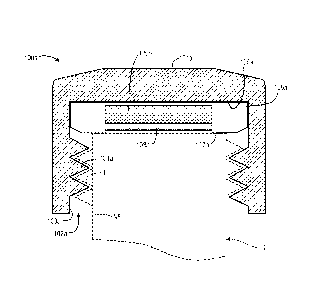
container can deform when exposed to a liquid that has been heated above the
glass transition
temperature (Tg) of the material from which the container is formed. Moreover,
steam and/or
other heated gas in a sealed container headspace will condense as the
container contents cool.
Headspace condensation produces a vacuum in sealed hot-filled containers.
[03] Most hot-fill beverage containers are designed to operate at or near
atmospheric
pressure. If such a container has a significant internal vacuum after it is
sealed, it will deform
and may buckle upon cooling. To avoid such distortion, any internal pressure
that is
significantly lower than external atmospheric pressure should be minimized
and/or the
container provided with appropriate structural support. Various techniques
have been
developed in this regard. For example, some PET container designs include
movable vacuum
panels or movable bases. Some hot-fill beverage containers have a thicker wall
construction.
These features result in heavier PET containers and increased material cost,
however. Other
techniques also have various drawbacks. Accordingly, there remains a need for
additional
techniques and devices that can reduce and/or relieve vacuum generated by hot-
filling of
deforrnable containers.
- 1 -
CA 02883681 2015-03-02
WO 2014/051963 PCT/US2013/058377
SUMMARY
[04] This Summary is provided to introduce a selection of concepts in a
simplified form
that are further described below in the Detailed Description. This Summary is
not intended to
identify key or essential features of the invention.
[05] In at least some embodiments, an adsorber material element is used
relieve a vacuum
that results from cooling of heated contents in a sealed container. An
interior volume of that
container may be filled or partially filled with a heated material. The heated
material may be
or may include a liquid. In some embodiments, the heated material may be a
beverage or
other food product intended for consumption by a human or animal. The
container may be
formed from any of a variety of materials and may have any of a variety of
shapes. In some
embodiments, the container may be formed from polyethylene terephthalate (PET)
or other
deformable material. The container may be at least partially filled with
liquid above 150 F
and sealed. After sealing, one or more gases may be released from an adsorber
material and
into the interior volume of the sealed container. As the contents of the
container cool, the
release of gas(es) from the adsorber material relieves vacuum that would
otherwise develop.
In at least some embodiments, the gas release is initially gradual, with full
release of gas
occurring after the contents of the container have cooled below the Tg of the
container
material.
[06] In some embodiments, an adsorber material insert may be incorporated into
a
container closure. Multiple closures may be stored in a pre-charging chamber
to pre-charge
the closure inserts with one or more gases. As containers are filled with
heated beverage,
closures may be dispensed from the pre-charging chamber and used to seal
filled containers.
[07] Additional embodiments are described herein.
BRIEF DESCRIPTION OF THE DRAWINGS
[08] Some embodiments are illustrated by way of example, and not by way of
limitation,
in the figures of the accompanying drawings and in which like reference
numerals refer to
similar elements.
- 2 -
CA 02883681 2015-03-02
WO 2014/051963 PCT/US2013/058377
[09] FIG. lA is a partially schematic area cross-sectional view of a
container closure,
according to some embodiments, that includes an adsorbent material insert.
[10] FIG. 1B is a partially schematic area cross-sectional view of a
container closure
according to some additional embodiments.
[11] FIG. IC is a partially schematic area cross-sectional view of a
container closure
according to some further embodiments.
[12] FIGS. 2A through 2E are partially schematic drawings showing steps in a
method,
according to some embodiments, utilizing a closure such as shown in FIGS. 1A-
1C.
[13] FIG. 3 is a block diagram showing steps of methods, according to at least
some
embodiments, for relieving vacuum in sealed containers caused by cooling of
container
contents.
[14] FIGS. 4A and 4B are partially schematic drawings showing use of a
pressurized
capping device during performance of a method according to some embodiments.
DETAILED DESCRIPTION
[15] In at least some embodiments, an adsorber material element is used
relieve a vacuum
that results from cooling of heated contents in a sealed container. As used
herein, a
"vacuum" refers to a pressure within an internal volume of a sealed container
that is less than
a pressure in an external space that surrounds the sealed container. As also
used herein,
"relieving" a vacuum includes reducing a vacuum, i.e., reducing the difference
between a
pressure within a sealed container internal volume and a pressure in the
external space that
surrounds the container. "Relieving" a vacuum may also include completely
eliminating a
vacuum, i.e., causing the container internal volume pressure to be equal to or
greater than an
external space pressure. "Relieving" a vacuum may also encompass avoiding
creation of a
vacuum, e.g., releasing gas from an adsorber material at a rate that is
sufficiently fast to
prevent an container internal volume pressure from becoming less than an
external space
pressure as the container contents cool.
- 3 -
CA 02883681 2015-03-02
WO 2014/051963 PCT/US2013/058377
[16] In some embodiments, an adsorber material element may be in the form of
an insert.
That insert, which may include one or multiple types of adsorber materials,
may be housed in
a closure used to seal the container. Prior to placement of an insert-housing
closure onto a
container filled with heated material and sealing the container, the adsorber
material(s) may
be pre-charged (also known as pre-loaded) with one or more gases. Those gases
can include,
without limitation, nitrogen (N2), methane (CH4), ethane (C2H4), carbon
dioxide (CO2),
and/or other gases. When the container is filled and ready for capping, the
closure (which
includes the pre-charged adsorber material(s)) is placed onto the container
and the container
is sealed. Gas is released from the adsorber material(s) housed in the insert.
The release of
gas from the adsorber material(s) as the container contents cool relieves the
vacuum
associated with cooling of those contents and condensing of vapor and/or gases
in the
container headspace. Additional aspects of methods and devices according to
these and other
embodiments are described below.
[17] FIG. IA is a partially schematic area cross-sectional view of a
container closure
100a, according to some embodiments, that includes an adsorbent material
insert. Closure
100a includes a housing 101a. The outer shape of housing 101a is generally
cylindrical. The
sectioning plane of FIG. lA passes through the vertical centerline of closure
100a.
[18] Closure 100a is configured for attachment to a threaded neck finish of a
polyethylene
terephthalate (PET) beverage container in a conventional manner. In
particular, a cavity 102a
in the underside of housing 101a is configured to receive a finish portion of
a container neck.
For reference purposes, FIG. IA shows a neck finish NF of a container C in
broken lines. An
interior sidewall 103a of cavity 102a includes helical threads 104a formed
thereon. When
closure 100a is placed onto a container neck finish and turned, threads 104a
engage with
corresponding threads (T) on the neck finish to secure closure 100a to the
container. Housing
101a can be molded from any of various thermoplastic or other materials
conventionally used
for container closures.
[19] The upper end of cavity 102a terminates in a liner well 105a. Closure
100a further
includes a disc-shaped liner 106a positioned in liner well 105a. Similar to
liners of
conventional beverage container closures, liner 106a acts to seal a container
when closure
- 4 -
CA 02883681 2015-03-02
WO 2014/051963 PCT/US2013/058377
100a is secured to a container neck finish. Specifically, bottom surface 107a
of liner 106a is
pressed against a sealing surface on the top edge of a neck finish when
closure 100a is
tightened onto that neck finish.
[20] Unlike conventional liners, however, liner 106a holds an adsorber
material insert
120a. Insert 120a contains one or more adsorber materials that have been
selected based on
an ability to adsorb a desired gas under one set of conditions and to then
release the adsorbed
gas under a different set of conditions. For example, the adsorber material(s)
may adsorb the
selected gas(es) under conditions that comprise a relatively high
concentration of the selected
gas(es) at a relatively high pressure. The adsorber material(s) may release
the adsorbed
gas(es) under conditions that comprise a lower pressure and/or the presence of
added
moisture.
[21] Gases that may be adsorbed and then released into a container according
to various
embodiments include, without limitation, one or more of the following:
nitrogen (N2),
methane (CH4), ethane (C2H6) and carbon dioxide (CO2). Gases that are
minimally soluble in
liquid (or other container contents) may be preferred in at least some
embodiments. In some
embodiments, an adsorber material insert or other type of adsorber material
element may only
be pre-charged with a single type of gas. When that adsorber material element
is later
exposed to the sealed container interior, that single type of gas is released.
In other
embodiments, an adsorber material element or collection of adsorber material
elements may
be pre-charged with multiple types of gases. When that adsorber material
element or element
collection is later exposed to the sealed container interior, each of those
multiple types of gas
may be released. In at least some embodiments, multiple gas adsorber material
elements may
be utilized to control the rate and release characteristics of adsorbed
gas(es) as a function of
time.
[22] Numerous types of adsorber materials are known in the art, including,
without
limitation, zeolites, carbon, carbon nanotubes and metal organic frameworks
(M0Fs). One
example of an MOF that may be used in some embodiments and that can be used to
adsorb
CO2, CH4 and/or N2 is available under the trade name BASOLITE C300 from Sigma-
Aldrich
Co. LLC of St. Louis, Missouri, US. Other adsorbers that can be used include,
without
- 5 -
limitation, 13X zeolite, activated carbon and 5A zeolite. These materials,
which can also be
used to adsorb CO2, CI-14 and/or N2, are well-known and commercially available
from
numerous sources.
[23] In some embodiments, an adsorber material insert or other adsorber
material element
may only include a single type of adsorber material. For example, an insert
may be
configured to adsorb a single gas, e.g., gas A. Adsorber material X adsorbs
gas A, and thus
an adsorber material insert configured to adsorb (and subsequently release)
gas A might only
include adsorber material X. In other embodiments, an adsorber material
element may be
comprised of multiple different types of adsorber materials. As another
example, an adsorber
material insert may be configured to adsorb two different types of gas, e.g.,
gas B and gas C.
Adsorber material Y may be a good adsorber of gas B but a poor adsorber of gas
C.
Similarly, adsorber material Z may be a good adsorber of gas C but a poor
adsorber of gas B.
Thus, an adsorber insert configured to adsorb (and subsequently release) gases
B and C could
contain a mixture of adsorber materials Y and Z. Alternatively, multiple
adsorber inserts
containing different types of adsorbers could be used to release one or more
gases.
[24] In some embodiments, insert 120a is formed as a solid disc before being
embedded
into liner 106a. In addition to one or more adsorber materials, insert 120a
may include one or
more binder materials (e.g., clay, fibers, polymers, waxes, cements) so as to
maintain the
integrity of insert 120a as a solid disc. In some embodiments, insert 120a is
solid, but may
have a different shape so as to maximize exposed surface area. For example,
instead of a
solid disc, insert 120a could be in the form of a solid spur with multiple
spokes. In still other
embodiments, the adsorber material(s) of insert 120a may be in granular form.
For example,
insert 120a could be in the form of a pouch formed by an outer membrane
holding particles
of adsorber material(s). Examples of such an embodiment are described below in
connection
with FIG. 1C.
[25] Liner
106a includes a semipermeable region 108a located directly under insert 120a.
Semipermeable region 108a allows gas escaping from insert 120a to pass through
liner 106a
and reach an interior volume of a container sealed by closure 100a. Region
108a also allows
some moisture from that interior volume to reach insert 120a. As explained in
further detail
- 6 -
CA 2883681 2017-06-20
CA 02883681 2015-03-02
WO 2014/051963 PCT/US2013/058377
below, such moisture may in some embodiments trigger the release of gas from
insert 120a.
In the embodiment of closure 100a, liner 106a is formed from two types of
material. The
first type of material is used for semipermeable region 108a and the second
type is used for
the remainder of liner 106a. The second type of material is not permeable to
gas or moisture.
Examples of materials that can be used for the non-permeable portions of liner
106a include,
without limitation, aluminum foil laminated elements. Examples of materials
from which
semipermeable region 108a can be formed include, without limitation,
thermoplastic
elastomers (TPEs), styrene ethylene butylene styrene (SEBS) terpolymer and
ethylene vinyl
acetate (EVA).
[26] FIG. 1B is a partially schematic cross-sectional view of a container
closure 100b
according to some additional embodiments. Except as described below, closure
100b is
similar to enclosure 100a. Unless indicated otherwise, an element in FIG. 1B
having a
reference number ending with a "b" is similar to and operates in the same
manner as the
element of FIG. IA having a like reference number ending with an "a." For
example,
housing 10Ib in FIG. 1B is similar to and operates in the same manner as
housing 101a of
FIG. IA.
[27] Closure 100b differs from closure 100a because of liner 106b. Unlike
liner 106a,
where semipermeable region 108a is formed from a different material than other
portions of
liner 106a, semipermeable region 108b of liner 106b is formed from the same
non-permeable
material used to form other portions of liner 106b. So that region 108b will
allow gas
released from insert 120b to reach a container interior volume and allow
moisture from the
container interior to reach insert 120b, a plurality of small pores 109b are
formed in region
108b.
[28] FIG. 1C is a partially schematic area cross-sectional view of a
container closure 100c
according to some further embodiments. Except as described below, closure 100c
is similar
to enclosure 100a. Unless indicated otherwise, an element in FIG. 1C having a
reference
number ending with a "c" is similar to and operates in the same manner as the
element of
FIG. lA having a like reference number ending with an "a." For example,
housing 101c in
FIG. IC is similar to and operates in the same manner as housing 101a of FIG.
1A.
- 7 -
CA 02883681 2015-03-02
WO 2014/051963 PCT/US2013/058377
[29] Closure 100c includes an adsorber insert 120c that differs from the
solid inserts 120a
and 120b of FIGS. lA and 1B. Insert 120c comprises multiple particles 123c of
one or more
types of adsorber materials. Unlike the solid inserts in FIGS. lA and 1B,
particles 123c are
not bound together to form a solid monolithic adsorber material element.
Instead, particles
123c are held together in a pouch between two sheets 121c and 122c of membrane
material.
Each of sheets 121c and 122c may be generally circular in shape. Particles
123c may be
placed between sheets 121c and 122c. Sheets 121c and 122c can then be joined
around their
peripheral edges 125c to form a flattened, circular pouch that secures
particles 123c within a
perimeter formed by a seal around peripheral edges 125c. At least membrane
121c may
formed from a semipermeable material such as SEBS.
[30] Semipermeable region 108a of closure 100a liner 106a may also act to
moderate the
rate at which gas diffuses from insert 120a to a container interior. In a
similar fashion, region
108b of liner 106b (closure 100b) and membrane 121c (element 120c within liner
106c of
closure 100c) may also act to moderate the rate at which gas diffuses from an
adsorber insert
to a container interior.
[31] Closures 100a-100c can be fabricated in a variety of ways. For example,
insert 120a-
120c could first be formed. In some embodiments, and depending on the adsorber
material(s)
selected, insert 120a or 120b might be formed by molding the selected adsorber
material(s) in
a matrix of one or more binder materials to form a solid disc. As indicated
above, insert 120c
could be formed by sealing the selected adsorber material(s) between sheets of
membrane
material. The non-permeable portion of liner 106a may molded into place around
insert
120a, after which semipermeable region 108a could be molded into place. After
molding of
liner 106a is complete, liner 106a could be placed into well 105a of housing
101a. Housing
101a could be injection molded in a conventional manner. In other embodiments,
a
previously formed insert 120a could be placed in a well of housing 101a and
liner 106a could
be molded in place around insert 120a. Similar operations could be used to
fabricate closures
100b or 100c, with modifications to accommodate differences in the various
embodiments.
For example, pores 109b in closure 100b could be formed during the process of
molding liner
106b by using small pins or other mold elements.
- 8 -
CA 02883681 2015-03-02
WO 2014/051963 PCT/US2013/058377
[32] FIGS. 2A through 2E are partially schematic drawings illustrating steps
in a method
according to some embodiments utilizing closures such as those of FIGS. lA
through 1C.
Because the method described in connection with FIGS. 2A-2E could be performed
using any
of closures 100a-100c, or using closures according to other embodiments, the
closure in
FIGS. 2A-2E will simply be referenced as closure 100.
[33] FIG. 2A shows a pre-charging chamber 200 that holds a supply of closures
100.
Chamber 200 is positioned near a capping machine that will receive closure 100
from
chamber 200 and use that received closure 100 to seal a container, as
described in further
detail below. Chamber 200 includes a main chamber 201 and a dispensing chamber
202.
Main chamber 201 maintains an atmosphere of gas G at a pressure of up to 6
bars. The
supply of closures 100 remain in main chamber 201 to pre-charge each their
adsorber inserts
120 with gas G. Gas G could be N2, CH4, C2H6, CO2 and/or other gas or
combination of
multiple gases. Dispensing chamber 202 acts to prevent depressurization of
main chamber
201 when a closure 100 is removed from chamber 200 and used to seal a
container.
Dispensing chamber 202 includes an inner door 203, and outer door 204, a gas G
supply line
controlled by a valve 205 and a vent line controlled by a valve 206.
[34] To dispense a closure from pre-charging chamber 200 for use in sealing a
container,
outer door 204, inner door 203 and vent valve 206 are closed. Gas G valve 205
is opened and
dispensing chamber 202 is pressurized to 6 bars (or to the same pressure as
main chamber
201, if different), and then valve 205 is closed. Inner door 203 is then
opened, a closure 100
is moved from main chamber 201 to dispensing chamber 202, and inner door 203
is closed.
Vent valve 206 is then opened to release the excess pressure within dispensing
chamber 202,
after which outer door 204 is opened and closure 100 is moved from dispensing
chamber 202
to the capping machine. For convenience, FIG. 2A shows a closure 100 already
positioned in
dispensing chamber 202. FIG. 2A further assumes that dispensing chamber 202 is
pressurized, gas G valve 205 is closed and vent valve 206 is closed.
[35] FIG. 2A further shows a container 220 that will ultimately be capped and
sealed by
one of the pre-charged closures 100 in chamber 200. Container 220 is located
near a filling
machine, but has not yet been filled. Container 220 includes a neck finish 221
similar to the
- 9 -
CA 02883681 2015-03-02
WO 2014/051963 PCT/US2013/058377
neck finish NF of FIGS. 1A-1C and onto which a closure 100 will be attached.
Neck finish
221 surrounds an opening 222 that exposes an interior volume 223 of container
220.
[36] FIG. 2B shows container 220 immediately after it has been filled with a
heated liquid
224. In particular, the filling machine has dispensed a quantity of heated
liquid 224 into
interior volume 223 through opening 222. Filled container 220 was then moved
to the
capping machine immediately after filling and while liquid 222 is still hot.
[37] FIG. 2C shows the start of the capping step. In some embodiments, a
container is
sealed within one second of being hot-filled. A pre-charged closure 100 is
dispensed from
chamber 200. In particular, vent valve 206 opens, outer door 204 opens, and a
closure 100 is
dispensed from dispensing chamber 202 to the capping machine. After dispensing
a closure
100 to the capping machine, outer door 204 and vent valve 206 close and
dispensing chamber
202 may begin loading another pre-charged closure for use in sealing another
container.
[38] Immediately upon being exposed to atmospheric pressure, the pre-charged
adsorber
material insert within the dispensed closure 100 begins to release gas G.
Accordingly, and as
shown in FIG. 2D, the capping machine quickly secures the closure 100 to neck
finish 211 of
container 220 and seals container 220. Once container 220 is sealed, any gas G
released from
insert of the closure 100 will be released to interior volume 223 of container
220.
[39] This is shown schematically in FIG. 2D. Specifically, the small arrows
moving
downward from closure 100 indicate that release of gas G has begun. Although
not shown in
FIG. 2D, the contents of container 220 (liquid 224 and vapor in headspace 225)
have started
to cool. Gas G released from insert 120 thus helps to relieve vacuum pressure
that would
otherwise form within interior volume 220 as liquid 224 cools.
[40] As further shown in FIG. 2D, operations associated with loading of
another closure
100 into dispensing chamber 202 also continue. Valve 205 has already been
opened to
pressurize chamber 205 with gas G and then closed. Inner door 203 has now been
opened
and a closure 100 has been moved from chamber 201 to chamber 202. Inner door
203 will
subsequently close and chamber 202 will then be ready to dispense the newly
loaded closure
- 10 -
CA 02883681 2015-03-02
WO 2014/051963 PCT/US2013/058377
100 for use in sealing the next filled container. Although not shown, that
next container
could be in position for filling at the filling machine as container 220 is
being capped in FIG.
2D.
[41] FIG. 2E shows a step in which sealed container 220 is inverted. This step
brings
heated liquid 224 into contact with closure 120 so as to sanitize closure 100.
The step also
causes moisture from liquid 224 to permeate to the adsorber material insert of
the closure
100. As indicated above in connection with FIGS. 1A-1C, this moisture could
permeate
through region 108a in the embodiment of FIG. 1A, through region 108b in the
embodiment
of FIG. 1B, or through membrane 121c in the embodiment of FIG. 1C. This
moisture acts to
trigger a more rapid release of gas from the insert, as indicated
schematically by the larger
arrows shown in FIG. 2E.
[42] Sealed container 220 may then be passed through a cooling tunnel (not
shown). As
container 220 passes through the cooling tunnel, it may be sprayed with water
so as to lower
the temperature of liquid 224 to approximately 165 F. As the temperature of
liquid 224
drops, gas G continues to be released from insert. This release of gas G
continues to relieve
vacuum within interior region 220.
[43] FIG. 3 is a block diagram show steps of methods, according to at least
some
embodiments, for relieving vacuum in sealed containers caused by cooling of
heated
container contents. Embodiments of the methods shown in FIG. 3 include the
embodiments
described above, as well as additional embodiments as set forth below.
[44] Step 300 includes at least partially filling an interior volume of a
container with a
heated material. In some embodiments the container is filled, but in other
embodiments the
container may not be completely filled. The container can have any of various
shapes. In
some embodiments, and as is shown in FIGS. 2A-2E, the container may be in the
shape of a
bottle having a neck portion. The neck portion may have an opening exposing an
interior
volume of the bottle. The neck portion may also include a finish that includes
threads or
other elements to secure a closure to seal the opening. Containers can have
other shapes and
-11-
CA 02883681 2015-03-02
WO 2014/051963 PCT/US2013/058377
configurations in other embodiments. Such shapes can include, without
limitation, jars,
cartons, canisters, etc.
[45] The container can also be formed of various materials. In at least some
embodiments,
the container is formed from a deformable material such as PET. In other
embodiments, the
container is formed from one or more other types of plastic materials. Such
other plastic
materials can include, without limitation, polyethylene naphthalate or other
resins with a Tg
of greater than 75 C. In still other embodiments, the container may be formed
from one or
more other plastic or non-plastic deformable materials. In yet other
embodiments, the
container may include one or more non-deformable portions. As used herein, an
element is
"non-deformable" if it does not show any noticeable deformation to the naked
eye when a
container incorporating the element is subjected to an unrelieved vacuum
pressure caused by
content cooling.
[46] In some embodiments, the heated material placed into the container during
step 300
is, or includes, a liquid. In at least some embodiments, the heated material
is a beverage or
other food product intended for consumption by a human or animal. The beverage
or other
food product may have any of numerous formulations, consistencies and/or
textures. The
beverage or other food product may be viscous, thin or watery, may or may not
have
inclusions (e.g., fruit pulp), etc. In some embodiments, the beverage or other
food product
may be gelatinous or a slurry. Examples of heated liquids with which a
container may be at
least partially filled in step 300 include, without limitation, fruit juices,
sports drinks and
other beverages, as well as dairy products. The heated material placed into
the container in
step 300 may be a mixture of other materials.
[47] The temperature to which the material is heated at the time of filling in
step 300 may
also vary by embodiment. That temperature may depend, at least in part, on the
material
being placed into the container. As used herein, "heated" means significantly
above room
temperature. In at least some embodiments, a material is heated to at least
150 F during the
at least partial filling of step 300. In other embodiments, the material is
heated to at least
160 F, to at least 165 F, to at least 170 F, to at least 175 F, to at least
180 F, to at least
185 F, or higher, during the at least partial filling of step 300.
- 12 -
CA 02883681 2015-03-02
WO 2014/051963 PCT/US2013/058377
[48] Step 305 includes sealing the container after the filling (or partial
filling) of the
container with the heated material. In some embodiments, and as described in
connection
with FIGS. 2A-2E, the sealing may include applying a closure and tightening or
otherwise
engaging sealing components of the closure. In some embodiments, for example,
a closure
may lack threads and may utilize a clip or other type of engaging mechanism to
secure the
closure to the container.
[49] A closure need not be used in all embodiments. In some embodiments, for
example,
the sealing operations of step 305 might include welding or otherwise
permanently closing an
opening on the container. For example, in some embodiments an adsorber insert
similar to
insert 120a might be wrapped in a semi-permeable material intended to
withstand long-term
immersion in the material within a sealed container. A supply of such inserts
could be pre-
charged in a chamber in a manner similar to the manner in which closures 100
are pre-
charged in chamber 200 in the embodiment of FIGS. 2A-2E. After filling a
plastic container
with a heated material (e.g., a beverage), a pre-charged inserts could be
dropped into the
container through a container opening and the container opening welded shut.
[50] Step 310 includes releasing a gas from an adsorber material element into
an interior
volume of the container after the container has been sealed. This adsorber
material element is
pre-charged with one or more gases such that those one or more gases are
adsorbed into pores
on the surface of the adsorber material(s). Prior to sealing the container in
step 305, the
adsorber material element is placed in a location so that gas(es) released
from the adsorber
material can flow into the container interior volume. In some embodiments, and
as described
in connection with FIGS. 1-2E, the adsorber material element is incorporated
into the sealing
liner of a closure. In other embodiments, an adsorber element could be located
elsewhere.
As indicated above, an adsorber material element could be formed as an insert
that is dropped
into a container prior to sealing. As another example, an adsorber material
element could be
incorporated into a container body. In such an embodiment, the container
itself could be pre-
charged with one or more gases in a manner similar to that in which closures
100 are pre-
charged in the embodiment of FIGS. 2A-2E. However, a container in such an
embodiment
- 13 -
CA 02883681 2015-03-02
WO 2014/051963 PCT/US2013/058377
could be removed from a pre-charging chamber just prior to filling and then be
immediately
filled and sealed.
[51] Once the container is sealed, exposure to conditions within the container
interior
volume (e.g., pressure drop, moisture) cause one or more gases to be released
from adsorber
material element. The released gas(es) flow into the container interior
volume. As the heated
material in the container cools, the ongoing release of gas(es) from the
adsorber material
element relieves vacuum caused by the cooling of the container contents.
[52] Different gases and/or combinations of gases can be released during step
310 in
various embodiments. As indicated above, those gases include, without
limitation, nitrogen
(N2), methane (CH4), ethane (C2H4) and carbon dioxide (CO2). Other gases can
include,
without limitation, hydrogen (H2) and helium (He). In some embodiments, gases
with low
aqueous solubility are selected so as to reduce the volume of gas that must be
released so as
to relieve vacuum. Numerous materials can be used as an adsorber material in
an adsorber
material element according to various embodiments. Those materials include,
without
limitation, the materials previously identified. An adsorber material element
may also
include other binders and other compounds to maintain the adsorber material(s)
as a
monolithic element. An adsorber material element may include adsorber
materials in
granular or other loose form that are contained by a membrane or other
barrier. An adsorber
material element may contain a single type of adsorber material (e.g., so as
to adsorb and
release a single gas) or may contain multiple types of adsorber materials
(e.g., so as to adsorb
and release multiple gases).
[53] In at least some embodiments, it is desirable to avoid deforming a
container when a
product filling that container is at a temperature above the Tg of the
container material. This
helps to avoid permanently expanding the container material to create an even
larger internal
volume. As a result, container shape and integrity can be maintained.
[54] So as to avoid permanently deforming the container when the contents are
above the
container material Tg, an adsorber, a matrix containing the adsorber and/or a
semipermeable
liner region surrounding the adsorber can be selected to result in a timed
release of adsorbed
- 14 -
CA 02883681 2015-03-02
WO 2014/051963 PCT/US2013/058377
gas. In particular, the adsorber, matrix and/or liner region can be selected
so that the
container is not overpressurized while the container contents are above Tg for
the container
material. Instead, gas is released gradually so that most of the adsorbed gas
is released after
the container contents cool below the container material Tg. For example, the
adsorber,
matrix and/or liner region can be selected so that less than 50% of the
adsorbed gas is
released upon filling of the container with heated product, and so that the
remainder is
released after the product has cooled below the container material Tg. One non-
limiting
example of an adsorber and matrix meeting this criteria is described below.
[55] In some additional embodiments of methods according to FIG. 3, an
adsorber material
element need not be precharged. In some such embodiments, gas(es) are added to
the
container in an additional step performed before, during or after the hot-
filling of step 300,
but prior to step 305. In particular, a dose of liquid nitrogen and/or other
liquefied gas(es)
can be added to the container just prior to sealing with a closure. The
closure can be similar
to closure 100, but the adsorber material element need not be precharged with
gas. After
sealing with the closure, the interior volume of the closure pressurizes as
the dose of liquefied
gas(es) evaporates. The elevated pressure within the container will cause the
gas(es) to be
adsorbed by the adsorber material element within the closure. The adsorption
will prevent
the container from becoming overpressurized while the contents are heated and
the container
is susceptible to plastic deformation. As the container contents cool and
pressure within the
sealed container drops, the adsorber material element releases the adsorbed
gas(es) back into
the container to reduce vacuum formation.
[56] In further embodiments, gas(es) G can be added to the container using a
pressurized
capping device during step 305. FIGS. 4A and 4B are partially schematic
drawings showing
use of such a device. In some such further embodiments, a capping machine may
include a
collar 401 that encloses the neck of the container 220. A bottom edge 402 may
include a
gasket to form a seal against the container outer wall and create a pressure
chamber 403.
Once collar 401 is lowered over the neck of a hot-filled container 220 and a
seal formed by
edge 402, pressurized gas(es) G can be released into pressure chamber 403. A
chuck or other
component (not shown) can then lower a closure 100 and seal that closure to
the neck finish
- 15 -
CA 02883681 2015-03-02
WO 2014/051963 PCT/US2013/058377
of container 220. The pressurized gas(es) G within chamber 403 begins to
adsorb into the
adsorber material element of closure 100 as closure 100 is being placed onto
the neck finish.
For a short time after closure 100 is secured, the gas(es) G within the
container 220
headspace will continue adsorbing into the adsorber material element of
closure 100. As with
the previously described embodiment, the adsorption may help prevent the
container from
becoming overpressurized while the contents are heated and the container is
susceptible to
plastic deformation. As the container contents cool and pressure within the
sealed container
drops, the adsorber material element releases the adsorbed gas(es) G back into
the container
to reduce vacuum formation (FIG. 4B).
Example 1
[57] An adsorber insert was formed by compounding approximately 2 grams of
zeolite
13X in EVA so that the EVA was approximately 70% loaded with the zeolite. The
insert was
charged with N2 at 10 bar for over a day. The insert was then placed in a
closure used to cap
a 20 ounce PET container that had been filled with hot water heated to 185 F.
The container
was allowed to cool in room temperature air. Internal pressure in the
container increased
from approximately -0.8 psig to approximately -0.7 psig in the first five
hours after
filling. The internal pressure progressively reached approximately -0.05 psig
overnight. The
container exhibited no appreciable buckling after 24 hours and was firm to
grip.
Conclusion
[58] The foregoing description of embodiments has been presented for purposes
of
illustration and description. The foregoing description is not intended to be
exhaustive or to
limit embodiments to the precise form explicitly described or mentioned
herein.
Modifications and variations are possible in light of the above teachings or
may be acquired
from practice of various embodiments. The embodiments discussed herein were
chosen and
described in order to explain the principles and the nature of various
embodiments and their
practical application to enable one skilled in the art to make and use these
and other
embodiments with various modifications as are suited to the particular use
contemplated.
- 16 -
CA 02883681 2015-03-02
WO 2014/051963 PCT/US2013/058377
Any and all permutations of features from above-described embodiments are the
within the
scope of the invention.
- 17 -