Note: Descriptions are shown in the official language in which they were submitted.
- 1 -
CA 02884175 2015-03-04
DESCRIPTION
METHOD AND SYSTEM FOR PRODUCING LIQUID FUEL AND GENERATING
POWER
Technical Field
[0001] The present invention relates to a method and a system for producing a
liquid fuel
such as gasoline from hydrocarbon gas such as natural gas, and for generating
power.
Background Art
[0002] As a method for producing gasoline from natural gas, JP 62-041276 B
discloses a
method in which synthetic gas is generated by steam-reforming natural gas,
methanol is
synthesized from the synthetic gas, and further, gasoline is synthesized from
the methanol.
In a reaction for synthesizing gasoline from methanol, a large amount of water
is generated in
addition to gasoline, but no method for using the generated water has been
formerly studied
yet.
[0003] On the other hand, JP 2000-054852 A discusses a combined cycle power
generation
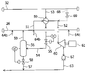
method which uses a gas turbine, in which a steam-reforming system is coupled
to a
combustor of the gas turbine.
Background Literature
Patent Literature
[0004] Patent Literature 1: JP 62-041276 B
Patent Literature 2: JP 2000-054852 A
Disclosure of Invention
Problem to be Solved by Invention
[0005] A steam-reforming reaction is run at a very high temperature as high as
about 800 C
or higher. In carrying out such a steam-reforming reaction, in order to
suppress precipitation
of carbon on a catalyst, it is necessary to supply steam in an amount greater
than that of
- 2
CA 02884175 2015-03-04
hydrocarbon gas, i.e., the feedstock. Accordingly, since excessive steam is
included in
reformed gas obtained by steam reforming, the reformed gas is condensed when
it is cooled,
and as a result, a large amount of heat is generated. However, because the
temperature of
most of the heat is as low as about 180 C or lower, this heat does not contain
any heat that is
suitable for use as recycled.
[0006] In consideration of the above-described problem, an object of the
present invention is
to provide a method and a system for producing a liquid fuel from reformed gas
generated by
a steam-reforming reaction and efficiently generating power by effectively
using low
temperature waste heat generated by the steam-reforming reaction.
Means for Solving the Problem
[0007] In order to achieve the above-described object, according to an aspect
of the present
invention, there is provided a method for producing a liquid fuel from
hydrocarbon gas and
for generating power, the method including the steps of: reforming hydrocarbon
gas to
generate reformed gas by a steam-reforming reaction of the hydrocarbon gas;
synthesizing
gasoline, dimethyl ether, or a diesel fuel from the reformed gas via methanol;
recovering heat
from thermal energy of the reformed gas to obtain saturated steam having a
temperature of at
most 180 C before using the reformed gas for the synthesis step; superheating
the saturated
steam by using a heat source having a temperature of at least 200 C generated
by the method
to obtain superheated steam; and generating power by using the superheated
steam.
[0008] Steam generated by an exothermic reaction in the synthesis step may be
used as the
heat source for the superheating in the superheating step. All of a methanol
synthesis
reaction, a gasoline synthesis reaction, a dimethyl ether (DME) synthesis
reaction, and a
diesel fuel synthesis reaction such as a Fischer-Tropsch process are
exothermic reactions.
Heat of these reactions alone or in combination with one another can be used
to generate
steam for heat recovery.
- 3 -
CA 02884175 2015-03-04
. [0009] A part of the reformed gas obtained in the reforming step may
be used as the heat
source for the superheating in the superheating step. Alternatively, flue gas
generated in the
reforming step may be used as the heat source for the superheating in the
superheating step.
[0010] According to another aspect of the present invention, there is provided
a system for
producing a liquid fuel from hydrocarbon gas and for generating power, the
system including:
a steam-reforming device for generating reformed gas by a steam-reforming
reaction of
hydrocarbon gas; a synthesis column for synthesizing gasoline, dimethyl ether,
or a diesel fuel
from the reformed gas via methanol; a heat exchanging device for obtaining
saturated steam
having a temperature of at most 180 C by heat exchanging of the reformed gas
before the
reformed gas is introduced in the synthesis column; a superheating device for
superheating the
. saturated steam by using a heat source having a temperature of at
least 200 C generated
within the system to obtain superheated steam; and a power generation device
for generating
power by using the superheated steam.
[0011] The heat source used in the superheating device may be steam generated
by an
exothermic reaction in the synthesis column. Alternatively, the heat source
used in the
superheating device may be a part of the reformed gas obtained by the steam-
reforming
device. Further alternatively, the heat source used in the superheating device
is flue gas
generated by the steam-reforming device.
Advantageous Effects of Invention
[0012] As described above, according to the present invention, by generating
superheated
steam by superheating saturated steam with a temperature as low as 180 C or
lower, the wet
region can be reduced if the pressure of the steam is lowered by a steam
turbine, and thereby a
high specific enthalpy of the steam can be obtained and the output of power
generation that
uses the steam can be greatly improved. Accordingly, by effectively using low-
temperature
waste heat as low as 180 C or lower generated by a steam-reforming reaction,
power can be
- 4 -
CA 02884175 2015-03-04
efficiently generated and a method and a system for producing a liquid fuel
from the reformed
gas generated by the steam-reforming reaction can be provided.
Brief Description of Drawings
- [0013] [FIG. 1] FIG. 1 is a schematic diagram showing an embodiment
of a system for
producing gasoline and generating power according to the present invention,
which illustrates
a flow of a process of producing gasoline from a feedstock.
[FIG. 2] FIG. 2 is a schematic diagram showing an embodiment of the system for
producing gasoline and generating power according to the present invention,
which illustrates
a flow of steam used for generating power.
[FIG. 3] FIG. 3 is a schematic diagram showing another embodiment of the
system
for producing gasoline and generating power according to the present
invention, which
illustrates a flow of steam used for generating power.
[FIG. 4] FIG. 4 is a schematic diagram showing yet another embodiment of the
system for producing gasoline and generating power according to the present
invention, which
illustrates a flow of steam used for generating power.
Description of Embodiments
[0014] Embodiments of the present invention will be described below with
reference to the
attached drawings. As shown in FIGs. 1 and 2, a gasoline production and power
generation
system according to the present embodiment includes main components such as a
steam
reformer 10, which is configured to generate reformed gas by steam-reforming
hydrocarbon
gas such as natural gas, a methanol synthesis column 30, which is configured
to synthesize
- methanol from the reformed gas generated by the steam reformer, a
gasoline synthesis column
40, which is configured to synthesize gasoline from the methanol synthesized
by the methanol
synthesis column, a low-pressure steam heat exchanger 25, which is arranged
between the
steam reformer and the methanol synthesis column and configured to obtain low-
pressure
- 5 -
CA 02884175 2015-03-04
steam from the reformed gas, a superheater 50, which is configured to
superheat the
low-pressure steam obtained by the heat exchanger, and a low-pressure steam
turbine 60,
which is configured to generate power by using the steam superheated by the
superheater.
[0015] The steam reformer 10 is provided with main components such as a
reaction tube 11
for steam reforming, a burning portion (not shown) 12 disposed around the
reaction tube 11, a
waste heat recovery portion 12, which is configured to recover waste heat of
flue gas
generated in the burning portion, and a stack 13, which is configured to
release the flue gas to
the atmosphere after waste heat has been recovered therefrom. The reaction
tube 11, which
includes a steam reforming catalyst charged inside the tube, is a device for
generating
hydrogen, carbon monoxide, and carbon dioxide from natural gas containing
methane as its
main ingredient by carrying out the following reactions. For the steam
reforming catalyst,
known catalysts such as a nickel-based catalyst can be used, for example.
CH4 + H20 ¨4 3H2 + CO (1)
CO +1120 ¨> H2 CO2 (2)
[0016] To a side of an inlet port of the reaction tube 11 of the steam
reformer 10, a feedstock
supply line 14 for supplying natural gas which is a feedstock and a steam
supply line 15 for
supplying steam from a boiler and the like (not shown) are connected. To a
side of an outlet
port of the reaction tube 11, a reformed gas supply line 21 is connected,
which is a line for
supplying reformed gas containing hydrogen, carbon monoxide, and carbon
dioxide generated
by a steam-reforming reaction as its main ingredients to the methanol
synthesis column 30.
Also connected to the steam reformer 10 is a fuel supply line 16 for supplying
a fuel to the
burning portion (not shown) for heating the reaction tube 11.
[0017] The reformed gas supply line 21 is provided with a high-pressure steam
heat
exchanger 23 configured to obtain high-pressure steam from the reformed gas in
the line, the
low-pressure steam heat exchanger 25 configured to obtain low-pressure steam
from the
- 6
CA 02884175 2015-03-04
reformed gas in the line, and a compressor 22 configured to compress the
reformed gas that
has gone through the heat exchangers to obtain a pressure suitable for the
synthesis of
methanol, which are arranged in this order from the side of the steam reformer
10. The heat
exchangers 23, 25 for high-pressure steam and low-pressure steam generate
steam by
performing heat exchange with the reformed gas. The compressor 22 compresses
the
reformed gas with a temperature lowered by the heat exchangers to a
predetermined pressure
before supplying the same to the methanol synthesis column 30.
[0018] The high-pressure steam heat exchanger 23 is provided with a high-
pressure steam
line 24 for supplying the generated high-pressure steam to a facility for a
predetermined
purpose. The low-pressure steam heat exchanger 25 is provided with a low-
pressure steam
line 26 for supplying the generated low-pressure steam to the low-pressure
steam turbine 60
illustrated in FIG. 2.
[0019] The methanol synthesis column 30 is a device configured to synthesize
methanol
from reformed gas by running the following reactions.
CO + 2H2 CH3OH (3)
CO2 + 3H2 ¨ CH3OH + H20 (4)
[0020] The methanol synthesis column 30 includes a methanol synthesis catalyst
charged
inside the tube. For the methanol synthesis catalyst, known catalysts such as
a copper-based
catalyst can be used. A methanol supply line 31 is connected to methanol
synthesis column
30, which is a line for supplying methanol synthesized by the methanol
synthesis column 30
to the gasoline synthesis column 40. In addition to the synthesized methanol,
liquid crude
methanol containing water, which is a byproduct of the reaction of Formula
(4), flows in the
methanol supply line 31.
[0021] The methanol synthesis reaction run in the methanol synthesis column 30
is an
exothermic reaction. Accordingly, middle-pressure steam can be obtained from
water by
- 7
CA 02884175 2015-03-04
using thermal energy generated by the methanol synthesis reaction run in the
methanol
synthesis column 30 as a heat source. The methanol synthesis column 30 is
provided with a
middle-pressure steam line 32 for supplying the middle-pressure steam that has
been obtained
in the above-described manner to a facility for a predetermined purpose, such
as the
superheater 50.
[0022] The gasoline synthesis column 30 is a device configured to synthesize
gasoline from
methanol by running the reactions expressed by the following Formulae.
2CH3OH ¨> CH3OCH3 + H20 (5)
1/2nCH3OCH3 ¨* (CH) n + 1/2nH20 (6)
[0023] As described above, methanol is synthesized by the gasoline synthesis
reaction
expressed by Formula (6) into gasoline via the dimethyl ether (DME) synthesis
reaction
expressed by Formula (5). In the gasoline synthesis column 40, two types of
catalysts
including a DME synthesis catalyst and a gasoline synthesis catalyst are
provided in two
. stages so that the two reactions can be run in stages. For the DME
synthesis catalyst, known
catalysts such as an aluminosilicate type zeolite-based catalyst can be used,
for example. In
addition, for the gasoline synthesis catalyst also, known catalysts such as an
alutninosilicate
type zeolite-based catalyst can be used.
[0024] A gasoline supply line 41 is connected to the gasoline synthesis column
40, which is
a line for supplying gasoline synthesized by the gasoline synthesis column 40
to storage
facilities (not shown). In addition, the above-described reaction run in the
gasoline synthesis
column 40 is an exothermic reaction. Accordingly, middle-pressure steam can be
obtained
from water by using thermal energy generated by the reaction run in the
gasoline synthesis
column 40 as a heat source. The gasoline synthesis column 40 is provided with
a
middle-pressure steam line 42 for supplying the middle-pressure steam obtained
in the
above-described manner to a facility for a predetermined purpose, such as the
superheater 50.
- 8
= CA 02884175 2015-03-04
[0025] As shown in FIG. 2, the superheater 50 is provided with a low-pressure
steam
extraction line 51 for supplying a part of low-pressure steam from the low-
pressure steam line
26 to the superheater 50, a superheated steam supply line 52 for supplying the
low-pressure
steam superheated by the superheater 50 to the low-pressure steam turbine 60,
a
middle-pressure steam extraction line 53 for supplying a part of middle-
pressure steam from
the middle-pressure steam line 32 to the superheater 50 as a superheat source,
and a waste
- steam line 54 in which the waste steam used by the superheater 50
flows. In other words,
the superheater 50 is a heat exchanger which superheats the low-pressure steam
generated by
the low-pressure steam heat exchanger 25 and its heat source is the middle-
pressure steam
generated by the methanol synthesis column 30. Note that the heat source can
be any
middle-pressure steam, i.e., the steam generated by the methanol synthesis
column 30, the
steam generated by the gasoline synthesis column 40, or both.
[0026] The low-pressure steam turbine 60 is provided with a generator 61,
which is driven
by the turbine and configured to generate power, and a steam condenser 62,
which is
configured to condense the steam used for driving the turbine back into water.
A discharge
- line 63 is connected to the steam condenser 62, which is a line for
discharging a steam
condensate into the steam generation system to be recycled there.
[0027] The waste steam line 54 is provided with a valve 55, which can be
controlled to be
opened or closed according to the steam pressure in the line. The waste steam
line 54 is
connected to a gas-liquid separation device 56. The gas-liquid separation
device 56 is a
device configured to perform gas-liquid separation for separating steam that
has been
introduced therein into reusable steam and condensed water. The gas-liquid
separation
device 56 is provided with a steam return line 59 for returning the reusable
steam to the
low-pressure steam line 26 and a condensed water line 57 for discharging the
condensed
water into a condensed water line 63. The low-pressure steam line 26 can be
provided with
- 9
CA 02884175 2015-03-04
an auxiliary line for supplying steam generated in a waste heat recovery
boiler (not shown) to
the low-pressure steam line where necessary. The condensed water line 57 is
provided with
a valve 58 that can be controlled to be opened or closed in accordance with
the liquid level of
the condensed water in the gas-liquid separation device 56.
[0028] In the above-described configuration, first, natural gas and steam from
the boiler (not
shown) are respectively supplied to the reaction tube 11 of the steam reformer
10 via the
feedstock supply line 14 and the steam supply line 15. In order to suppress
precipitation of
carbon on the catalyst in the reaction tube, it is preferable that the steam
be supplied at a
molar ratio of 2 or higher compared with hydrogen contained in the natural
gas.
[0029] The fuel is supplied to the burning portion (not shown) of the steam
reformer 10 via
the fuel supply line 16. The fuel is burned in the burning portion together
with air to heat the
reaction tube 11 up to a temperature of about 800 to 900 C. The temperature of
the flue gas
- containing carbon dioxide generated in the burning portion is about
1,000 C, and after having
gone through heat recovery in the waste heat recovery portion 12, the flue gas
is released from
the stack 13 into the atmosphere.
[0030] On the other hand, the natural gas and the steam that have been
supplied to the
reaction tube 11 are converted by the steam-reforming reaction into reformed
gas run in the
reaction tube 11. The temperature of the reformed gas is about 800 to 900 C,
and the
reformed gas is first introduced into the high-pressure steam heat exchanger
23 via a reformed
gas supply line 18. In the high-pressure steam heat exchanger 23, boiler water
and the like
are heated with the reformed gas, thus high-pressure steam having the
temperature of about
200 C or higher, for example, and a corresponding saturated steam pressure is
generated, and
thereby heat is recovered from the reformed gas. The high-pressure steam is
supplied to a
facility of a predetermined purpose via the high-pressure steam line 24.
[0031] The temperature of the reformed gas is lowered by the heat recovery
performed by
- 10
CA 02884175 2015-03-04
the high-pressure steam heat exchanger 23 to a temperature of about 200 to 300
C, for
example, before being introduced into the low-pressure steam heat exchanger
25. In the
low-pressure steam heat exchanger 25, the reformed gas heats the boiler water
and the like,
thus generates low-pressure steam having a temperature of about 100 to 180 C,
preferably a
temperature of about 100 to 180 C, for example, and a corresponding saturated
steam pressure,
and thereby heat is recovered from the reformed gas. The reformed gas cooled
by the heat
recovery down to the temperature of about 100 to 180 C is further cooled with
cooling water
and an air cooler before being introduced into the compressor 22. In the
compressor 22, the
temperature of the reformed gas is controlled to a temperature suitable for a
methanol
synthesis reaction (e.g., about 200 C) before supplying the reformed gas to
the methanol
synthesis column 30.
[0032] In the methanol synthesis column 30, methanol is synthesized by the
reactions
expressed by Formulae (3) and (4) from the reformed gas and carbon dioxide
gas. Because
the methanol synthesis reaction is an exothermic reaction, middle-pressure
steam with a
temperature of about 250 C and a corresponding saturated steam pressure can be
generated in
the methanol synthesis column 30 due to thermic energy. The methanol
synthesized by the
methanol synthesis column 30 is supplied to the gasoline synthesis column 40
via the
methanol supply line 31 as crude methanol containing water. The middle-
pressure steam is
supplied to a facility of a predetermined purpose via the middle-pressure
steam line 32.
[0033] In the gasoline synthesis column 40, gasoline is synthesized from
methanol by
running the reactions of Formulae (5) and (6). Because the gasoline synthesis
reaction is
also an exothermic reaction, middle-pressure steam with a temperature of about
250 C and a
corresponding saturated steam pressure can be generated in the gasoline
synthesis column 40
due to thermic energy. The gasoline synthesized by the gasoline synthesis
column 40 is
supplied to the storage facilities (not shown) via the gasoline supply line
41. The
- 11 -
CA 02884175 2015-03-04
middle-pressure steam is supplied to a facility of a predetermined purpose via
the
middle-pressure steam line 42.
[0034] Next, a part of the low-pressure steam which flows through the low-
pressure steam
line 26 is introduced into the superheater 50 via the low-pressure steam
extraction line 51 as
illustrated in FIG. 2. In addition, a part of the middle-pressure steam which
flows through
the middle-pressure steam line 32 is introduced to the superheater 50 via the
middle-pressure
steam extraction line 53 to superheat the low-pressure steam. By performing
the
superheating, the temperature of the low-pressure steam can be raised to a
temperature higher
than the temperature of the saturated steam by about 50 to 100 C. The low-
pressure steam
that has been superheated in the above-described manner is supplied to the low-
pressure
steam turbine 60 via the superheated steam supply line 52. In the low-pressure
steam turbine
60, the superheated low-pressure steam is inflated, the turbine is driven by
the kinetic energy
of the inflated steam, and thereby the generator 61 generates power.
[0035] Because the low-pressure steam supplied to the low-pressure steam
turbine 60 has
been superheated as described above, the level of wetness on the side of the
outlet port of the
low-pressure steam turbine can be reduced, thus the superheated low-pressure
steam can be
inflated to have a steam pressure of a low degree of vacuum, a high specific
enthalpy can be
obtained, and thereby the output from the low-pressure steam turbine 60 can be
greatly
improved. The steam that has been used by the low-pressure steam turbine 60 is
condensed
by the steam condenser 62 before being recycled into the steam generation
system via the
condensed water line.
[0036] On the other hand, the middle-pressure steam that has been used by the
superheater
50 is supplied to the gas-liquid separation device 56 via the waste steam line
54. In the
gas-liquid separation device 56, the pressure of the middle-pressure steam of
which the
temperature has been lowered due to the use thereof for the superheating is
lowered to the
- 12 -
CA 02884175 2015-03-04
- same pressure as that of the low-pressure steam, and then is gas-
liquid separated into reusable
steam and condensed water. The condensed water is discharged into the
condensed water
line via the condensed water line 57. The steam is supplied to the low-
pressure steam line
26 via the steam return line 59, then is superheated by the superheater 50,
and the superheated
steam can be reused for power generation by the low-pressure steam turbine 60.
[0037] Alternatively, instead of using the superheater 50, the low-pressure
steam can be
superheated by providing and using a steam mixing line 68 to the middle-
pressure steam line
32 as illustrated in FIG. 2. The steam mixing line 68 is a line for mixing a
part of the
middle-pressure steam that flows through the middle-pressure steam line with
the
- low-pressure steam that flows through the low-pressure steam
extraction line 51. With the
above-described configuration, the temperature of the low-pressure steam can
be raised to a
temperature higher than the temperature of the saturated steam by about 50 to
100 C. The
configuration that uses the steam mixing line 68 may of course be used
together with the
superheater 50. By providing the steam mixing line 68 with an open-close valve
69,
superheating means can be selected between the heat exchange by the
superheater 50 and the
mixing by the steam mixing line 68.
[0038] Although FIG. 1 illustrates the gasoline synthesis column 40, a DME
synthesis
column configured to produce DME by performing the process only up to a stage
of the DME
synthesis reaction expressed by Formula (5) can be provided instead of the
gasoline synthesis
column 40. Because the DME synthesis reaction also is an exothermic reaction,
the
middle-pressure steam can be generated by the DME synthesis column. Further
alternatively,
if a synthesis column that performs the Fischer-Tropsch process is provided
instead of the
methanol synthesis column 30 and the gasoline synthesis column 40 illustrated
in FIG. 1, a
diesel fuel can be obtained from the reformed gas. Because a Fischer-Tropsch
synthesis
reaction also is an exothermic reaction, the middle-pressure steam can also be
generated in
- 13 -
CA 02884175 2015-03-04
this configuration.
[0039] In the present invention, the heat source for superheating the low-
pressure steam is
not limited to the heat from the middle-pressure steam generated in the
methanol synthesis
column and the gasoline synthesis column. For example, alternatively, heat
from the
reformed gas generated by the steam reformer and heat from the flue gas can be
used as the
heat source. As configurations that can be used alternatively to the
configuration illustrated
in FIG. 2, FIG. 3 illustrates a configuration that uses the reformed gas
generated by the steam
reformer and FIG. 4 illustrates a configuration that uses flue gas from the
steam reformer. In
FIGs. 3 and 4, the same components as those illustrated in FIG. 2 are provided
with the same
reference signs and detailed descriptions thereof will not be repeated below.
[0040] As shown in FIG. 3, in the configuration in which the reformed gas
generated by the
steam reformer is used as the heat source for superheating, a superheater 70
is provided with a
low-pressure steam extraction line 71 for supplying a part of the low-pressure
steam from the
low-pressure steam line 26 to the superheater 70, a superheated steam supply
line 72 for
supplying the low-pressure steam superheated by the superheater 70 to the low-
pressure steam
turbine 60, a reformed gas extraction line 73 for supplying a part of the
reformed gas from the
reformed gas supply line 21 to the superheater 70 as the superheat source, and
a reformed gas
discharge line 74 in which the reformed gas that has been used by the
superheater 70 flows.
For the position of connection of the reformed gas extraction line 73 with the
reformed gas
supply line 21, the reformed gas extraction line 73 can be connected at a
location between the
steam reformer 10 and the high-pressure steam heat exchanger 23 or a location
between the
high-pressure steam heat exchanger 23 and the low-pressure steam heat
exchanger 25
illustrated in FIG. 1. The reformed gas discharge line 74 is connected to the
compressor 22
illustrated in FIG. 1. In addition, the reformed gas discharge line 74 is
provided with a
gas-liquid separation device 75, which is configured to remove condensed water
from the
- 14 -
CA 02884175 2015-03-04
reformed gas that has been used for the superheating.
[0041] In the above-described configuration, a part of the low-pressure steam
which flows
through the low-pressure steam line 26 is introduced into the superheater 70
via the
low-pressure steam extraction line 71. In addition, a part of the reformed gas
which flows
through the reformed gas supply line 21 is introduced to the superheater 70
via the reformed
gas extraction line 73 to superheat the low-pressure steam. By performing the
superheating,
the temperature of the low-pressure steam can be raised to a temperature
higher than the
temperature of the saturated steam by about 50 to 150 C, for example. The low-
pressure
steam that has been superheated in the above-described manner is supplied to
the
low-pressure steam turbine 60 via the superheated steam supply line 72. In the
low-pressure
steam turbine 60, the turbine is driven as described above and thereby power
is generated by
the generator 61. In this configuration also, the output from the low-pressure
steam turbine
60 can be greatly improved and the level of wetness of the steam that has been
used by the
low-pressure steam turbine 60 on the side of the outlet port of the turbine
can be improved.
[0042] On the other hand, the reformed gas that has been used by the
superheater 70 is
introduced into the gas-liquid separation device 75 via the reformed gas
discharge line 74.
Condensed water is separated by the gas-liquid separation device 75, then the
condensed
water is supplied to the methanol synthesis column 30 via the compressor 22
illustrated in
FIG. 1 as the feedstock for the methanol synthesis reaction.
[0043] As shown in FIG. 4, in the configuration in which the flue gas from the
steam
reformer is used as the heat source of the superheating, a superheater 80 is
provided to the
waste heat recovery portion 12 of the steam reformer 10. The superheater 80 is
provided
with a low-pressure steam extraction line 81 for supplying a part of the low-
pressure steam
from the low-pressure steam line 26 to the superheater 80 and a superheated
steam supply line
82 for supplying the low-pressure steam that has been superheated by the
superheater 80 to
- 15
CA 02884175 2015-03-04
the low-pressure steam turbine 60.
[0044] In the above-described configuration, a part of the low-pressure steam
which flows
through the low-pressure steam line 26 is introduced into the superheater 80
via the
low-pressure steam extraction line 81. The low-pressure steam is superheated
by the flue
gas that flows through the waste heat recovery portion 12 of the steam
reformer 10. By
performing this superheating, the temperature of the low-pressure steam can be
raised to a
temperature higher than the temperature of the saturated steam by about 50 to
150 C, for
example. The low-pressure steam that has been superheated in the above-
described manner
is supplied to the low-pressure steam turbine 60 via the superheated steam
supply line 82. In
the low-pressure steam turbine 60, the turbine is driven as described above
and thereby power
is generated by the generator 61. In this configuration also, the output from
the low-pressure
steam turbine 60 can be greatly improved and the level of wetness of the steam
that has been
used by the low-pressure steam turbine 60 can be improved.
Examples
[0045] Simulations of the steam to be supplied to the steam turbine which can
be obtained
by the superheating were carried out for the embodiments illustrated in FIGs.
2 to 4. The
results of the simulations are illustrated in Table 1. Conditions for the low-
pressure steam to
be the subject of the superheating in each embodiment were as follows:
temperature: 143 C,
pressure: 3 kg/cm2G, and
flow rate: 114.3 t/h.
- 16 -
CA 02884175 2015-03-04
[0046] Table 1
FIG. 2 FIG. 3 FIG. 4
Temperature of superheat source ( C) 331 200 300
Pressure of superheat source (kg/cm2G) 26.5 18.0 atmospheric
pressure
Flow rate of superheat source (t/h) 7.84 63.5 100
Temperature of superheated steam ( C) 210 190 210
Pressure of superheated steam (kg/cm2G) 2.8 2.8 2.8
Temperature of superheat source after
223 155 220
being used for superheating ( C)
Thermal energy for superheating (kcal/h) 3.96 x 10⁶ 2.8 x 10⁶ 3.96 x 10⁶
[0047] According to FIGs. 2 and 4, the steam with the temperature of 210 C and
the
pressure of 3 kg/cm2G is obtained by the superheating. If this steam is to be
used for
turbine-driven power generation, the amount of heat of 95 kcal/kg is obtained
by subtracting
590 kcal/kg from 685 kcal/kg, and as a result, the turbine output is 12,620
kw. On the other
hand, if the saturated steam with the pressure of 3 kg/cm2G is to be used for
turbine-driven
power generation, the amount of heat of 47 kcal/kg is obtained by subtracting
608 kcal/kg
from 655 kcal/kg, and as a result, the turbine output is 6,240 kw.
Accordingly, by carrying
out the superheating as illustrated in FIGs. 2 and 4, the turbine output can
be nearly doubled.
[0048] In addition, the moisture content is usually distilled off from
methanol generated by a
methanol synthesis column. In the reaction for synthesizing gasoline from
methanol, water
is generated at the same time as gasoline as expressed by Formulae (5) and
(6). Accordingly,
in the configuration illustrated in FIG. 1, provision of a distillation column
between the
methanol synthesis column and the gasoline synthesis column can be omitted. In
a plant
which includes a steam reformer and a methanol synthesis colurrm and produces
2,500 tons of
methanol per day, the thermal amount of about 60 x 106 kcal is required for
the distillation,
- 17 -
CA 02884175 2015-03-04
and in a configuration in which the distillation column is omitted, saturated
steam with the
pressure of 3 kg/cm2G can be generated by the heat exchanger for the reformed
gas of the
steam reformer at the flow rate of 114 t/h.
Description of Reference Numerals
[0049] 10: Steam reformer
11: Reaction tube
12: Waste heat recovery portion
13: Stack
14: Feedstock supply line
15: Steam supply line
16: Fuel supply line
21: Reformed gas supply line
22: Compressor
23: High-pressure steam heat exchanger
24: High-pressure steam line
25: Low-pressure steam heat exchanger
26: Low-pressure steam line
30: Methanol synthesis column
31: Methanol supply line
32: Middle-pressure steam line
40: Gasoline synthesis column
41: Gasoline supply line
42: Middle-pressure steam line
50, 70, 80: Superheaters
51, 71, 81: Low-pressure steam extraction lines
- 18 -
CA 02884175 2015-03-04
52, 72, 82: Superheated steam supply lines
53: Middle-pressure steam extraction line
54: Waste steam line
55: Valve
56: Gas-liquid separation device
57: Condensed water line
58: Valve
59: Steam return line
60: Low-pressure steam turbine
61: Generator
62: Steam condenser
63: Condensed water line
73: Reformed gas extraction line
74: Reformed gas discharge line
75: Gas-liquid separation device