Note: Descriptions are shown in the official language in which they were submitted.
DISTAL FEMUR CUTTING BLOCK AND METHOD OF
USING SAME
BACKGROUND
Within the last decade, orthopedic surgeons have successfully attached an
implant
to distal femurs to replace the medial joint and the patellofemoral joint.
While such an
implant has provided some patients with substantial relief from knee ailments,
many
patients have not benefitted from the implant. There are several reasons why
such
implants are not effective with some patients. One reason is based on the
sizing of the
implant, particularly relating to the medial, lateral, and the AP dimensions
of the implant.
Currently, there are only a limited number of standard sizes of implants for
use by
surgeons. Because of the limited selection of implants, surgeons are often
unable to
provide patients with correctly sized implants. Another reason for ineffective
implants is
the inability of the implant to properly rotate. The implant must be able to
properly rotate
for proper patellar tracking and for balancing the knee through a full range
of motion.
Unfortunately, the placement of a femoral implant in the proper rotation can
be difficult
for surgeons to accomplish in a reproducible fashion. As a result, the risk of
surgeon error
in the placement of femoral implants is relatively high. A third reason for
ineffective
implants is the lack of instrumentation available to surgeons to make cuts to
the distal
femur in a reproducible fashion.
Accordingly, there exists a need for an apparatus and method of using the
apparatus to prepare the distal femur for a joint replacement in a
customizable manner
such that all patients can benefit from the implant.
CAN_DMS: \110410097\1 1
CA 2884600 2018-02-06
SUMMARY
In one aspect, there is provided a distal femur cutting block comprising: a
first
portion defining a first external surface, said first external surface
including one or more
first passages therethrough; a second portion defining a second external
surface, said
second external surface including one or more second passages therethrough,
said first
portion hingedly connected to said second portion, wherein said first portion
and said
second portion may be rotated relative to each other through said hinged
connection; a
third surface opposite one of said first surface or said second surface, said
third surface
comprising contours configured to substantially mate with at least one condyle
of said
distal femur; and a fourth surface opposite the other one of said first
surface and said
second surface, said fourth surface comprising contours configured to
substantially mate
with at least one condyle of said distal femur.
The present disclosure includes disclosure of a distal femur cutting block and
method of using the same. In at least one embodiment, such a distal femur
cutting block
comprises a first portion defining a first external surface, the first
external surface
including one or more first
1A
CA 2884600 2018-09-10
CA 02884600 2015-03-10
WO 2014/043503 PCT/US2013/059710
passages therethrough; and a second portion defining a second external
surface, the second
external surface including one or more second passages therethrough, the first
portion hingedly
connected to the second portion, wherein the first portion and the second
portion may be rotated
relative to each other through the hinged connection; and a third surface
opposite one of the first
surface or the second surface, the third surface comprising contours
configured to substantially
mate with at least one condyle of the distal femur. In an aspect of such an
embodiment, at least
one of the first passages comprises a cylindrical passage sized to receive a
pin for fastening the
first portion to the distal femur. In an aspect of such an embodiment, at
least one of the second
passages comprises a cylindrical passage sized to receive a drill for removing
bone from the
I 0 distal femur. In an aspect of such an embodiment, at least one of the
second passages comprises
a slot sized to receive an orthopedic bone saw blade for cutting the distal
femur. In an aspect of
such an embodiment, the second passages comprise slots for receiving one or
more orthopedic
bone saw blades, the slots being sufficient in number and arrangement to
enable the distal femur
in contact with the third portion to be shaped for receiving a femoral implant
without removing
the distal femur from the distal femur cutting block. In an aspect of such an
embodiment, the
first portion, the second portion, and the hinged connection are constructed
from a single nylon
article.
In at least one embodiment, such a distal femur cutting block comprises a
first portion
defining a first external surface, the first external surface containing one
or more first passages
therethrough, the first portion comprising a seam along a longitudinal axis
thereof, the seam
dividing the first portion into two substantially similar sections; a second
portion defining a
second external surface, the second external surface containing one or more
second passages
therethrough, the second portion being integral with and arranged at
substantially a right angle to
the first portion, the seam continuing into the second portion but not through
the second external
.. surface thereby forming a hinge at the second external surface; and a third
surface opposite one
of the first surface or the second surface, the third surface comprising
contours configured to
substantially mate with at least one condyle of the distal femur. In an aspect
of such an
embodiment, at least one of the first passages comprises a cylindrical passage
sized to receive a
pin for fastening the first portion to the distal femur. In an aspect of such
an embodiment, at
least one of the second passages comprises a cylindrical passage sized to
receive a drill for
removing bone from the distal femur. In an aspect of such an embodiment, at
least one of the
2
CA 02884600 2015-03-10
WO 2014/043503 PCT/US2013/059710
second passages comprises a slot sized to receive an orthopedic bone saw blade
for cutting the
distal femur. In an aspect of such an embodiment, the second passages comprise
slots for
receiving one or more orthopedic bone saw blades, the slots being sufficient
in number and
arrangement to enable the distal femur in contact with the third portion to be
shaped for receiving
a femoral implant without removing the distal femur from the distal femur
cutting block. In an
aspect of such an embodiment, the first portion and the second portion are
constructed from a
single nylon article,
In at least one embodiment, such a distal femur cutting block comprises a
block having a
first surface, the first surface comprising contours configured to
substantially mate with at least
one condyle of a distal femur, and a second surface opposing the first
surface; and at least one
passage through the block, the at least one passage configured to permit a
medical instrument
introduced into the passage at the first surface to emerge from the passage at
the second surface,
wherein when the second surface is adjacent the at least one condyle of the
distal femur, the
medical instrument is aligned by the passage into a position to contact the at
least one condyle.
In an aspect of such an embodiment, at least one of the passages comprises a
cylindrical passage
sized to receive a pin for fastening the first block to the distal femur. In
an aspect of such an
embodiment, at least one of the passage comprises a cylindrical passage sized
to receive a drill
for removing bone from the distal femur. In an aspect of such an embodiment,
at least one of the
passages comprises a slot sized to receive an orthopedic bone saw blade for
cutting the distal
femur, in an Aspect of such an embodiment, the passages comprise slots for
receiving one or
more orthopedic bone saw blades, the slots being sufficient in number and
arrangement to enable
the distal femur in contact with the first surface to be shaped for receiving
a femoral implant
without removing the distal femur from the contact with the first surface. In
an aspect of such an
embodiment, the distal femur cutting block further comprises a seam along the
first surface, the
seam dividing the first surface into two substantially similar sections, the
seam continuing into
the block but not through the second surface thereby forming a hinge at the
second external
surface.
In at least one embodiment, such a method for utilizing a distal femur cutting
block
comprises the steps of receiving at least a portion of a distal femur in a
distal femur cutting
block; performing operations on the distal femur using guides on the distal
femur cutting block;
removing the distal femur cutting block from the distal femur; and applying an
implant to the
3
CA 02884600 2015-03-10
WO 2014/043503 PCT/US2013/059710
distal femur. In an aspect of such an embodiment, the distal femur cutting
block comprises a
flexible hinge, and the step of receiving at least a portion of a distal femur
in a distal femur
cutting block comprises the step of bending the distal femur cutting block at
the flexible hinge.
BRIEF DESCRIPTION OF THE DRAWINGS
The features and advantages of this disclosure, and the manner of attaining
them, will be
more apparent and better understood by reference to the following descriptions
of the disclosed
methods and systems, taken in conjunction with the accompanying drawings,
wherein:
Figure 1 shows a side view of a distal femur cutting block according to at
least one
1() .. embodiment of the present disclosure;
Figure 2 shows a top view of a distal femur cutting block according to at
least one
embodiment of the present disclosure;
Figure 3 shows a bottom perspective view of a distal femur cutting block
according to at
least one embodiment of the present disclosure;
Figure 4 shows a front view of a distal femur cutting block according to at
least one
embodiment of the present disclosure;
Figure 5 shows a side view of a distal femur cutting block according to at
least one
embodiment of the present disclosure;
Figure 6 shows a side view of a distal femur cutting block according to at
least one
embodiment of the present disclosure in the presence of a distal femur;
Figure 7 shows a side view of a distal femur cutting block according to at
least one
embodiment of the present disclosure in the presence of a distal femur;
Figure 8 shows a side view of a distal femur cutting block according to at
least one
embodiment of the present disclosure in the presence of a distal femur;
Figure 9 shows a top perspective view of a distal femur cutting block
according to at least
one embodiment of the present disclosure in the presence of a distal femur;
Figure 10 shows a bottom perspective view of a distal femur cutting block
according to at
least one embodiment of the present disclosure in the presence of a distal
femur;
Figure 11 shows a bottom perspective view of a distal femur cutting block
according to at
least one embodiment of the present disclosure;
4
CA 02884600 2015-03-10
WO 2014/043503 PCT/US2013/059710
Figure 12 shows a bottom view of a distal femur cutting block according to at
least one
embodiment of the present disclosure;
Figure 13 shows a top view of a distal femur cutting block according to at
least one
embodiment of the present disclosure;
Figure 14 shows an anterior view of a distal femur cutting block according to
at least one
embodiment of the present disclosure;
Figure 15 shows an end view of a distal femur cutting block according to at
least one
embodiment of the present disclosure;
Figure 16 shows a side view of a distal femur cutting block according to at
least one
embodiment of the present disclosure;
Figure 17 shows a top view of a distal femur cutting block according to at
least one
embodiment of the present disclosure;
Figure 18 shows a bottom perspective view of a distal femur cutting block
according to at
least one embodiment of the present disclosure;
Figure 19 shows a front view of a distal femur cutting block according to at
least one
embodiment of the present disclosure;
Figure 20 shows a side view of a distal femur cutting block according to at
least one
embodiment of the present disclosure;
Figure 21 shows a side view of a distal femur cutting block according to at
least one
embodiment of the present disclosure in the presence of a distal femur;
Figure 22 shows a side view of a distal femur cutting block according to at
least one
embodiment of the present disclosure in the presence of a distal femur;
Figure 23 shows a side view of a distal femur cutting block according to at
least one
embodiment of the present disclosure in the presence of a distal femur;
Figure 24 shows a top perspective view of a distal femur cutting block
according to at
least one embodiment of the present disclosure in the presence of a distal
femur;
Figure 25 shows a bottom perspective view of a distal femur cutting block
according to at
least one embodiment of the present disclosure in the presence of a distal
femur;
Figure 26 shows a flowchart illustrating a method of utilizing a distal femur
cutting block
according to at least one embodiment of the present disclosure;
5
CA 02884600 2015-03-10
WO 2014/043503 PCT/US2013/059710
Figure 27 shows a side view of a distal femur cutting block according to at
least one
embodiment of the present disclosure in the presence of a distal femur;
Figure 28 shows a side view of a distal femur cutting block according to at
least one
embodiment of the present disclosure in the presence of a distal femur;
Figure 29 shows a side view of a distal femur cutting block according to at
least one
embodiment of the present disclosure in the presence of a distal femur;
Figure 30 shows a side view of a distal femur cutting block according to at
least one
embodiment of the present disclosure in the presence of a distal femur;
Figure 31 shows a side view of a distal femur cutting block according to at
least one
embodiment of the present disclosure in the presence of a distal femur;
Figure 32 shows a side view of a distal femur cutting block according to at
least one
embodiment of the present disclosure in the presence of a distal femur;
Figure 33 shows a bottom perspective view of a distal femur cutting block
according to at
least one embodiment of the present disclosure;
Figure 34 shows a top view of a distal femur cutting block according to at
least one
embodiment of the present disclosure;
Figure 35 shows a bottom perspective view of a distal femur cutting block
according to at
least one embodiment of the present disclosure;
Figure 36 shows an anterior view of a distal femur cutting block according to
at least one
embodiment of the present disclosure;
Figure 37 shows an anterior view of a distal femur cutting block according to
at least one
embodiment of the present disclosure in the presence of a distal femur;
Figure 38 shows an anterior view of a distal femur cutting block according to
at least one
embodiment of the present disclosure in the presence of a distal femur; and
Figure 39 shows an anterior view of a distal femur cutting block according to
at least one
embodiment of the present disclosure in the presence of a distal femur.
6
CA 02884600 2015-03-10
WO 2014/043503 PCT/US2013/059710
DESCRIPTION
For the purposes of promoting an understanding of the principles of the
present
disclosure, reference will now be made to the embodiments illustrated in the
drawings, and
specific language will be used to describe the same. It will nevertheless be
understood that no
limitation of the scope of this disclosure is thereby intended.
Figure 1 shows a distal femur cutting block 100 according to at least one
embodiment of
the present disclosure. A distal femur cutting block 100 of the present
disclosure can be used by
surgeons or other medical professionals to prepare a patient's distal femur
for various types of
knee surgery, such as the replacement of the medial joint and the
patellofemoral joint, a total
knee replacement, a unicompartmental replacement, and the like, As described
herein, a distal
femur cutting block 100 of the present disclosure is designed to fit over a
portion of the distal
femur and act as a guide for surgeons or other medical professionals when
performing full or
partial knee replacement surgeries.
The size and shape of the distal femur cutting block 100 according to the
present
disclosure are based upon the size and shape of the implant for the knee
procedure. In at least
one embodiment, the size and shape of the distal femur cutting block 100
according to the
present disclosure may be chosen based upon the results of a CT scan and/or
MRI of the patient's
distal femur. That is, the distal femur cutting block 100 according to the
present disclosure can
be customized to substantially match the outer surface of the patient's distal
femur using results
from CT scans and/or MRIs of the distal femur. In order to further reduce the
chance for
surgeon errors and improve patient outcomes, the location, orientation, number
of, and
configuration of guides for cuts and pin placements may also be determined
based upon CT
scans and/or MRIs of the patient's distal femur. By having all of the cuts
performed with the
guidance of a single distal femur cutting block 100 (instead of multiple
blocks used sequentially
to carry out the needed cuts), the errors associated with cutting the distal
femur can be reduced
and patient outcomes can be improved. A distal femur cutting block 100 of the
present
disclosure can improve the selection of a properly sized femoral implant,
improve the ability of
the implant to properly rotate (leading to a better range of motion for the
patient), and decrease
operative time since surgeons can rely on the distal femur cutting block 100
for guidance. A
distal femur cutting block 100 according to the present disclosure may be
formed of a variety of
suitable materials, including, but not limited to, nylon.
7
CA 02884600 2015-03-10
WO 2014/043503 PCT/US2013/059710
As shown in Figure 1, a distal femur cutting block 100 according to at least
one
embodiment of the present disclosure is a monolithic cutting block including
anterior portion 110
with anterior surface 150, and distal portion 120 with distal surface 160.
Anterior portion 110
and distal portion 120 are connected through hinge 130, which is formed of the
same material as
anterior portion 110 and distal portion 120. When hinge 130 is in a closed
position, anterior
portion 110 and distal portion 120 are substantially perpendicular to one
another. However, in at
least one embodiment of the present disclosure when hinge 130 is in a closed
position anterior
portion 110 and distal portion 120 may be arranged relative to each other in a
relationship that is
less than or greater than perpendicular.
Figure 2 shows a top view of a distal femur cutting block 100 according to at
least one
embodiment of the present disclosure, Shown in Figure 2 is receiving portion
105 comprising
the internal surfaces of anterior portion 110 and distal portion 120.
Receiving portion 105 is
configured to fit around the distal femur of a patient such that a surgeon or
other medical
professional can prepare the femur for receiving an implant, The internal
surfaces of anterior
portion 110 and distal portion 120 that form receiving portion 105 are
contoured to fit snugly
around the femoral condyles. Through the use of CT scans and/or MR1s, the
contours of
receiving portion 105 may be designed to closely match at least a portion of
the femoral
condyles.
Figure 3 shows a bottom perspective view of a distal femur cutting block 100
according
to at least one embodiment of the present disclosure. Figure 3 shows anterior
portion 110
including anterior surface 150, and distal portion 120 including distal
surface 160. As shown in
Figure 3, hinge 130 is in a closed position with anterior portion 110 and
distal portion 120 at a
substantially right angle. Figure 4 shows a front view of a distal femur
cutting block according
to at least one embodiment of the present disclosure,
Shown in Figures 3-4 are pin guides 112 and 124. Pin guides 122 extend
completely
through anterior portion 110. Pin guides 124 extend completely through distal
portion 120. In at
least one embodiment, one or more of pin guides 112 and 124 may comprise a
countersink
configuration. As discussed herein, when distal femur cutting block 100 is
positioned around a
patient's distal femur, pins or screws may be inserted through pin guides 112
and 124 into the
patient's distal femur in order to securely mount distal femur cutting block
100 to the patient's
distal femur for a knee implant surgical procedure. Also shown in Figure 3 are
cutting guides
8
CA 02884600 2015-03-10
WO 2014/043503 PCT/US2013/059710
122. Cutting guides 122 extend through distal portion 120. In at least one
embodiment, one or
more cutting guides 122 may extend through distal portion 120 in an alignment
that is
substantially perpendicular to the bottom surface of distal portion 120. In at
least one
embodiment, one or more cutting guides 122 may extend through distal portion
120 in an
alignment that is not perpendicular to the bottom surface of distal portion
120, As discussed
herein, after distal femur cutting block 100 is positioned around and secured
to a patient's distal
femur, cutting instruments may be inserted thorough cutting guides 122 in
order to accurately cut
the femoral condyles into the shape needed to receive a knee implant. The
placement of pin
guides 112 and 124 and cutting guides 122 may be determined through the use of
CT scans
.. and/or MRI scans in order to ensure that once the block 100 is attached to
the distal femur, the
surgeon or other medical professional will have the correct locations to cut
the femoral condyles
and/or insert pins.
Figures 5-10 show a step-by-step process of applying distal femur cutting
block 100 to a
distal femur DF, according to at least one embodiment of the present
disclosure. As shown in
Figure 5, anterior portion 110 and distal portion 120 are rotated relative to
one another around
hinge 130 to form an open configuration such that the distal femur DF can be
received within the
receiving portion 105 of distal femur cutting block 100. As shown in Figures 6-
7, distal femur
DF is inserted within the receiving portion 105 of the distal femur cutting
block 100, which is
still in the flexed configuration. As shown in Figure 8, anterior portion 110
and distal portion
120 are rotated relative to one another around hinge 130 to close anterior
portion 110 and distal
portion 120 around distal femur cutting block 100 around distal femur DF. As
shown in Figure
8, hinge. 130 is in a closed position and anterior portion 110 and distal
portion 120 are
substantially perpendicular to one another.
Figure 9 shows a top perspective view of a distal femur cutting block 100
according to at
.. least one embodiment of the present disclosure closed around a distal
femur. After distal femur
cutting block 100 is closed around a distal femur, pins or screws may be
inserted through pin
guides 112 into the patient's distal femur in order to securely mount distal
femur cutting block
100 to the patient's distal femur for a knee implant surgical procedure.
Figure 10 shows a bottom perspective view of a distal femur cutting block 100
according
to at least one embodiment of the present disclosure closed around a distal
femur. After distal
femur cutting block 100 is closed around a distal femur, pins or screws may be
inserted through
9
CA 02884600 2015-03-10
WO 2014/043503 PCT/US2013/059710
pin guides 124 into the patient's distal femur in order to securely mount
distal femur cutting
block 100 to the patient's distal femur for a knee implant surgical procedure.
As discussed
herein, after distal femur cutting block 100 is positioned around a patient's
distal femur and after
distal femur cutting block 100 is secured to a patient's distal femur by pins
or screws inserted
through pin guides 112 and 124 into the patient's distal femur, cutting
instruments may be
inserted thorough cutting guides 122 in order to accurately cut the femoral
condyles into the
shape needed to receive a knee implant. Such cuts may include one or more of
posterior cut,
posterior chamber cut, anterior chamber cut, anterior cut, distal femoral cut,
and transition cut.
Figure 11 shows a bottom perspective view of a distal femur cutting block 1100
according to at least one embodiment of the present disclosure. A distal femur
cutting block
1100 according to the present disclosure may be formed of a variety of
suitable materials,
including, but not limited to, nylon. Shown in Figure 11 are pin guides 302
and 304. Pin guides
302 and 304 extend completely through distal femur cutting block 1100. In at
least one
embodiment, one or more of pin guides 302 and 304 may comprise a countersink
configuration.
When distal femur cutting block 1100 is positioned on a patient's distal
femur, pins or screws
may be inserted through pin guides 302 and 304 into the patient's distal femur
in order to
securely mount distal femur cutting block 1100 to the patient's distal femur
for a knee implant
surgical procedure. Also shown in Figure 11 are cutting guides 224, 306, 308,
310, 312, and
314. Cutting guides 224, 306, 308, 310, 312, and 314 extend through distal
femur cutting block
1100. In at least one embodiment, one or more of cutting guides 224, 306, and
308 may extend
through distal femur cutting block 1100 in an alignment that is substantially
perpendicular to
bottom surface 1160 of distal femur cutting block 1100. In at least one
embodiment, one or
more of cutting guides 310 and 312 may extend through distal femur cutting
block 1100 in an
alignment that is not perpendicular to the bottom surface 1160 of distal femur
cutting block
1100. In at least one embodiment, cutting guide 314 may extend through distal
femur cutting
block 1100 in an alignment that is substantially perpendicular to front
surface 1162 of distal
femur cutting block 1100. As discussed herein, after distal femur cutting
block 1100 is
positioned on and secured to a patient's distal femur, cutting instruments may
be inserted
thorough cutting guides 224, 306, 308, 310, 312, and 314 in order to
accurately cut the femoral
condyles into the shape needed to receive a knee implant, or to accurately
drill holes into the
femoral condyles to facilitate attachment of a knee implant. The placement of
pin guides 302
CA 02884600 2015-03-10
WO 2014/043503 PCT/US2013/059710
and 304, and cutting guides 224, 306, 308, 310, 312, and 314 may be determined
through the use
of CT scans and/or MRI scans in order to ensure that once distal femur cutting
block 1100 is
attached to the distal femur, the surgeon or other medical professional will
have the correct
locations to cut the femoral condyles and/or insert pins. By having all of the
cuts performed with
the guidance of a single distal femur cutting block 1100 (instead of multiple
blocks used
sequentially to carry out the needed cuts), the errors associated with cutting
the distal femur can
be reduced and patient outcomes can be improved.
Figure 12 shows a bottom view of a distal femur cutting block 1100 according
to at least
one embodiment of the present disclosure, including front surface 1162 and
rear surface 1163.
Shown in Figure 12 are pin guides 302 and 304, and cutting guides 224, 306,
308, 310, and 312.
Figure 13 shows a top view of a distal femur cutting block 1100 according to
at least one
embodiment of the present disclosure, including top surface 1161, front
surface 1162, and rear
surface 1163. Shown in Figure 13 are pin guides 302 and 304, and cutting
guides 224, 306, 308,
310, and 312. Also shown in Figure 13 are impressions 316. Impressions 316
comprise
contoured portions of the top surface 1161 of distal femur cutting block 1100.
Impressions 316
arc contoured to fit against the femoral condyles. Through the use of CT scans
and/or MRIs, the
contours of impressions 316 may be configured to closely match at least a
portion of the femoral
condyl es.
Figure 14 shows an anterior view of a distal femur cutting block 1100
according to at
least one embodiment of the present disclosure. Shown in Figure 14 is front
surface 1162 with
cutting guide 314 extending therethrough,
Figure 15 shows an end view of a distal femur cutting block 1100 according to
at least
one embodiment of the present disclosure. Shown in Figure 14 are pin guides
302,
Figure 16 shows a distal femur cutting block 200 according to at least one
embodiment of
the present disclosure. As described herein, a distal femur cutting block 200
of the present
disclosure is designed to fit over a portion of the distal femur and act as a
guide for surgeons or
other medical professionals when performing full knee replacement surgeries.
The size and shape of the distal femur cutting block 200 according to the
present
disclosure are based upon the size and shape of the implant for the knee
procedure. In at least
one embodiment, the size and shape of the distal femur cutting block 200
according to the
present disclosure may be chosen based upon the results of a CT scan and/or
MRI of the patient's
11
CA 02884600 2015-03-10
WO 2014/043503 PCT/US2013/059710
distal femur. That is, the distal femur cutting block 200 according to the
present disclosure can
be customized to substantially match the outer surface of the patient's distal
femur using results
from CT scans and/or MRIs of the distal femur. In order to further reduce the
chance for
surgeon errors and improve patient outcomes, the location, orientation, number
of, and
configuration of guides for cuts and pin placements may also be determined
based upon CT
scans and/or MRIs of the patient's distal femur. By having all of the cuts
performed with the
guidance of a single distal femur cutting block 200 (instead of multiple
blocks used sequentially
to carry out the needed cuts), the errors associated with cutting the distal
femur can be reduced
and patient outcomes can be improved. A distal femur cutting block 200 of the
present
disclosure can improve the selection of a properly sized femoral implant,
improve the ability of
the implant to properly rotate (leading to a better range of motion for the
patient), and decrease
operative time since surgeons can rely on the distal femur cutting block 200
for guidance. A
distal femur cutting block 200 according to the present disclosure may be
formed of a variety of
suitable materials, including, but not limited to, nylon.
As shown in Figure 16, a distal femur cutting block 200 according to at least
one
embodiment of the present disclosure is a monolithic cutting block including
anterior portion 210
with anterior surface 250, and distal portion 220 with distal surface 260.
Anterior portion 210
and distal portion 220 are connected through hinge 230, which is formed of the
same material as
anterior portion 210 and distal portion 220. When hinge 230 is in a closed
position, anterior
portion 210 and distal portion 220 are substantially perpendicular to one
another. However, in at
least one embodiment of the present disclosure when hinge 230 is in a closed
position anterior
portion 210 and distal portion 220 may be arranged relative to each other in a
relationship that is
less than or greater than perpendicular.
Figure 17 shows a top view of a distal femur cutting block 200 according to at
least one
embodiment of the present disclosure. Shown in Figure 17 is receiving portion
205 comprising
the internal surfaces of anterior portion 210 and distal portion 220,
Receiving portion 205 is
configured to fit around the distal femur of a patient such that a surgeon or
other medical
professional can prepare the femur for receiving an implant. The internal
surfaces of anterior
portion 210 and distal portion 220 that form receiving portion 205 are
contoured to fit snugly
around the femoral condyles. Through the use of CT scans and/or MRIs, the
contours of
12
CA 02884600 2015-03-10
WO 2014/043503 PCT/US2013/059710
receiving portion 205 may be designed to closely match at least a portion of
the femoral
condyles.
Figure 18 shows a bottom perspective view of a distal femur cutting block 200
according
to at least one embodiment of the present disclosure. Figure 18 shows anterior
portion 210
including anterior surface 250, and distal portion 220 including distal
surface 260. As shown in
Figure 18, hinge 230 is in a closed position with anterior portion 210 and
distal portion 220 at a
substantially right angle. Figure 19 shows a front view of a distal femur
cutting block according
to at least one embodiment of the present disclosure.
Shown in Figures 18-19 are pin guides 212, 302, and 304. Pin guides 212 extend
completely through anterior portion 210. Pin guides 302 and 304 extend
completely through
distal portion 220. In at least one embodiment, one or more of pin guides 212,
302, and 304 may
comprise a countersink configuration, As discussed herein, when distal femur
cutting block 200
is positioned around a patient's distal femur, pins or screws may be inserted
through pin guides
212, 302, and 304 into the patient's distal femur in order to securely mount
distal femur cutting
block 200 to the patient's distal femur for a knee implant surgical procedure.
Also shown in
Figure 18 are cutting guides 224, 306, 308, 310, and 312. Cutting guides 224,
306, 308, 310, and
312 extend through distal portion 220. In at least one embodiment, cutting
guides 224, 306, and
308 may extend through distal portion 220 in an alignment that is
substantially perpendicular to
the bottom surface of distal portion 220, In at least one embodiment, a
cutting guides 310 and
312 may extend through distal portion 220 in an alignment that is not
perpendicular to the
bottom surface of distal portion 220. As discussed herein, after distal femur
cutting block 200 is
positioned around and secured to a patient's distal femur, cutting instruments
may be inserted
thorough cutting guides 224, 306, 308, 310, and 312 in order to accurately cut
the femoral
condyles into the shape needed to receive a knee implant, or to accurately
drill holes into the
femoral condyles to facilitate attachment of a knee implant. The placement of
pin guides 212,
302, and 304, and cutting guides 224, 306, 308, 310, and 312 may be determined
through the use
of CT scans and/or MRI scans in order to ensure that once the block 200 is
attached to the distal
femur, the surgeon or other medical professional will have the correct
locations to cut the
femoral condyles and/or insert pins.
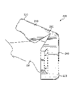
Figures 20-25 show a step-by-step process of applying distal femur cutting
block 200 to a
distal femur DF, according to at least one embodiment of the present
disclosure. As shown in
13
CA 02884600 2015-03-10
WO 2014/043503 PCT/US2013/059710
Figure 20, anterior portion 210 and distal portion 220 are rotated relative to
one another around
hinge 230 to form an open configuration such that the distal femur DF can be
received within the
receiving portion 205 of distal femur cutting block 200, As shown in Figures
21-22, distal femur
DF is inserted within the receiving portion 205 of the distal femur cutting
block 200, which is
still in the flexed configuration. As shown in Figure 23, anterior portion 210
and distal portion
220 are rotated relative to one another around hinge 230 distal femur cutting
block 200 around
distal femur DE As shown in Figure 23, hinge 230 is in a closed position and
anterior portion
210 and distal portion 220 are substantially perpendicular to one another.
Figure 24 shows a top perspective view of a distal femur cutting block 200
according to
.. at least one embodiment of the present disclosure closed around a distal
femur. After distal
femur cutting block 200 is closed around a distal femur, pins or screws may be
inserted through
pin guides 212 into the patient's distal femur in order to securely mount
distal femur cutting
block 200 to the patient's distal femur for a knee implant surgical procedure.
Figure 25 shows a bottom perspective view of a distal femur cutting block 200
according
to at least one embodiment of the present disclosure closed around a distal
femur. After distal
femur cutting block 200 is closed around a distal femur, pins or screws may be
inserted through
pin guides 302 and 304 into the patient's distal femur in order to securely
mount distal femur
cutting block 200 to the patient's distal femur for a knee implant surgical
procedure. As
discussed herein, after distal femur cutting block 200 is positioned around a
patient's distal femur
and after distal femur cutting block 200 is secured to a patient's distal
femur by pins or screws
inserted through pin guides 212, 302, and 304 into the patient's distal femur,
cutting instruments
may be inserted thorough cutting guides 224, 306, 308, 310, and 312 in order
to accurately cut
the femoral condyles into the shape needed to receive a knee implant or to
accurately drill holes
into the femoral condyles to facilitate attachment of a knee implant. Such
cuts may include one
.. or more of posterior cut, posterior chamber cut, anterior chamber cut,
anterior cut, distal femoral
cut, and transition cut.
Figure 26 shows a method 2600 of utilizing a distal femur cutting block
according to at
least one embodiment of the present disclosure. As shown in Figure 26, such a
method includes
the step 2610 of applying the distal femur cutting block to the patient's
distal femur. In
.. particular, the distal femur cutting block may be arranged into an open
configuration (as
described herein) such that the distal femur can be received by the distal
femur cutting block.
14
CA 02884600 2015-03-10
WO 2014/043503 PCT/US2013/059710
After at least a portion of the distal femur is received by the distal femur
cutting block, the block
is adjusted to be in a closed configuration (as described herein) in order to
closely mate with the
distal femur and substantially lock the block in place relative to the distal
femur. As shown in
Figure 26, the method 2600 also includes the step 2620 of performing
procedures on the distal
femur using the guides on the surfaces of the block, such as, for example,
pinning down the
block anteriorly and/or distally to the distal femur and carrying out a series
of cuts to the distal
femur including one or more of posterior cut, posterior chamber cut, anterior
chamber cut,
anterior cut, distal femoral cut, and transition cut. As shown in Figure 26,
the method 2600 also
includes the step 2630 of taking the block off of the distal femur. This step
2630 may include
removing one or more pins that were applied in step 2620. Figure 26 also shows
that the method
2600 may optionally include the step 2635 of applying an implant to the distal
femur.
Figures 27-32 show sides view of a distal femur cutting block 1100
illustrating its use
cutting instruments. As shown in Figures 27-32, distal femur cutting block
1100 is attached to
distal femur by pins 303 inserted through pin guides 302, and also by pins
inserted through other
pin guides not shown in Figures 27-32,
In Figure 27, cutting tool 224A is inserted into cutting guide 224. Cutting
tool 224A in
this example is a drill. In Figure 28, cutting tool 306A is inserted into
cutting guide 306. Cutting
tool 306A in this example is a saw. In Figure 29, cutting tool 308A is
inserted into cutting guide
308. Cutting tool 308A in this example is a saw, In Figure 30, cutting tool
310A is inserted into
cutting guide 310. Cutting tool 310A in this example is a saw. In Figure 31,
cutting tool 312A is
inserted into cutting guide 312. Cutting tool 312A in this example is a saw.
In Figure 32, cutting
tool 314A is inserted into cutting guide 314. Cutting tool 314A in this
example is a saw.
Figure 33 shows a bottom perspective view of a distal femur cutting block 1100
according to at least one embodiment of the present disclosure. As discussed
elsewhere herein,
distal femur cutting block 1100 according to the present disclosure may be
formed of a variety of
suitable materials, including, but not limited to, nylon, Shown in Figure 33
are pin guides 302
and 304. Pin guides 302 and 304 extend completely through distal femur cutting
block 1100. In
at least one embodiment, one or more of pin guides 302 and 304 may comprise a
countersink
configuration. Also shown in Figure 33 is hinge 430, which is formed in distal
femur cutting
block 1100 at approximately the midpoint of front surface 1162. Although hinge
430 is shown
in Figure 33 at approximately the midpoint of front surface 1162, the location
of hinge 430 is not
CA 02884600 2015-03-10
WO 2014/043503 PCT/US2013/059710
limited to this position. Hinge 430 may be offset toward one end of distal
femur cutting block
1100 or the other. Hinge 430 may be formed across the longer dimension of
distal femur cutting
block 1100 (i.e., perpendicular to the orientation shown in Figure 33), at or
near the midpoint or
offset toward one end of distal femur cutting block 1100 or the other. Hinge
430 also may be
formed at a diagonal between opposing surfaces of distal femur cutting block
1100. When distal
femur cutting block 1100 is positioned on a patient's distal femur, pins or
screws may be inserted
through pin guides 302 and 304 into the patient's distal femur in order to
securely mount distal
femur cutting block 1100 to the patient's distal femur for a knee implant
surgical procedure.
Also shown in Figure 33 are cutting guides 224, 306, 308, 310, 312, and 314.
Cutting guides
224, 306, 308, 310, 312, and 314 extend through distal femur cutting block
1100. In at least one
embodiment, one or more of cutting guides 224, 306, and 308 may extend through
distal femur
cutting block 1100 in an alignment that is substantially perpendicular to
bottom surface 1160 of
distal femur cutting block 1100. In at least one embodiment, one or more of
cutting guides 310
and 312 may extend through distal femur cutting block 1100 in an alignment
that is not
perpendicular to the bottom surface 1160 of distal femur cutting block 1100.
In at least one
embodiment, cutting guide 314 may extend through distal femur cutting block
1100 in an
alignment that is substantially perpendicular to front surface 1162 of distal
femur cutting block
1100. As discussed herein, distal femur cutting block 1100 can be flexed at
hinge 430 in order to
position on distal femur cutting block 1100 on a patient's distal femur.
Distal femur cutting
block 1100 then can be secured to the patient's distal femur, and cutting
instruments may be
inserted thorough cutting guides 224, 306, 308, 310, 312, and 314 in order to
accurately cut the
femoral condyles into the shape needed to receive a knee implant, or to
accurately drill holes into
the femoral condyles to facilitate attachment of a knee implant. The placement
of pin guides 302
and 304, and cutting guides 224, 306, 308, 310, 312, and 314 may be determined
through the use
of CT scans and/or MRI scans in order to ensure that once distal femur cutting
block 1100 is
attached to the distal femur, the surgeon or other medical professional will
have the correct
locations to cut the femoral condyles and/or insert pins. By having all of the
cuts performed with
the guidance of a single distal femur cutting block 1100 (instead of multiple
blocks used
sequentially to carry out the needed cuts), the errors associated with cutting
the distal femur can
.. be reduced and patient outcomes can be improved.
16
CA 02884600 2015-03-10
WO 2014/043503 PCT/US2013/059710
Figure 34 shows a top view of a distal femur cutting block 1100 according to
at least one
embodiment of the present disclosure, including top surface 1161, front
surface 1162, and rear
surface 1163. Shown in Figure 34 are pin guides 302 and 304, and cutting
guides 224, 306, 308,
310, and 312. Also shown in Figure 34 are impressions 316. Impressions 316
comprise
contoured portions of the top surface 1161 of distal femur cutting block 1100.
Impressions 316
are contoured to fit against the femoral condyles. Through the use of CT scans
and/or MRIs, the
contours of impressions 316 may be configured to closely match at least a
portion of the femoral
condyles. Also shown in Figure 34 is the location of hinge 430, which is
formed in distal femur
cutting block 1100 at approximately the midpoint of top surface 1161. Although
hinge 430 is
shown in Figure 34 at approximately the midpoint of top surface 1161, the
location of hinge 430
is not limited to this position. Hinge 430 may be offset toward one end of
distal femur cutting
block 1100 or the other, Hinge 430 may be formed across the longer dimension
of distal femur
cutting block 1100 (i.e,, perpendicular to the orientation shown in Figure
34), at or near the
midpoint or offset toward one end of distal femur cutting block 1100 or the
other. hinge 430
also may be formed at a diagonal between opposing surfaces of distal femur
cutting block 1100.
As discussed herein, distal femur cutting block 1100 can be flexed at hinge
430, thereby
separating top surface 1161 in order to facilitate positioning of distal femur
cutting block 1100
on a patient's distal femur,
Figure 35 shows a bottom perspective view of a distal femur cutting block 200
according
to at least one embodiment of the present disclosure, Figure 35 shows anterior
portion 210
including anterior surface 250, and distal portion 220 including distal
surface 260. Shown in
Figure 35 are pin guides 212, 302, and 304. Pin guides 212 extend completely
through anterior
portion 210. Pin guides 302 and 304 extend completely through distal portion
220, In at least
one embodiment, one or more of pin guides 212, 302, and 304 may comprise a
countersink
configuration. Also shown in Figure 35 is the location of hinge 530, which is
formed in distal
femur cutting block 200 at approximately the midpoint of distal portion 220.
Although hinge
530 is shown in Figure 35 at approximately the midpoint of distal portion 220,
the location of
hinge 530 is not limited to this position. Hinge 530 may be offset toward one
end of distal femur
cutting block 200 or the other, Hinge 530 also may be formed at a diagonal. As
discussed
herein, distal femur cutting block 200 can be flexed at hinge 530, thereby
separating anterior
portion 210 in order to facilitate positioning of distal femur cutting block
200 on a patient's distal
17
CA 02884600 2015-03-10
WO 2014/043503 PCT/US2013/059710
femur. As discussed herein, when distal femur cutting block 200 is positioned
around a patient's
distal femur, pins or screws may be inserted through pin guides 212, 302, and
304 into the
patient's distal femur in order to securely mount distal femur cutting block
200 to the patient's
distal femur for a knee implant surgical procedure. Also shown in Figure 35
are cutting guides
224, 306, 308, 310, and 312. Cutting guides 224, 306, 308, 310, and 312 extend
through distal
portion 220. In at least one embodiment, cutting guides 224, 306, and 308 may
extend through
distal portion 220 in an alignment that is substantially perpendicular to the
bottom surface of
distal portion 220. In at least one embodiment, a cutting guides 310 and 312
may extend through
distal portion 220 in an alignment that is not perpendicular to the bottom
surface of distal portion
220, As discussed herein, after distal femur cutting block 200 is positioned
around and secured
to a patient's distal femur, cutting instruments may be inserted thorough
cutting guides 224, 306,
308, 310, and 312 in order to accurately cut the femoral condyles into the
shape needed to
receive a knee implant, or to accurately drill holes into the femoral condyles
to facilitate
attachment of a knee implant. The placement of pin guides 212, 302, and 304,
and cutting
guides 224, 306, 308, 310, and 312 may be determined through the use of CT
scans and/or MRI
scans in order to ensure that once the block 200 is attached to the distal
femur, the surgeon or
other medical professional will have the correct locations to cut the femoral
condyles and/or
insert pins.
Figure 36 shows an anterior view of a distal femur cutting block 1100
according to at
least one embodiment of the present disclosure, Shown in Figure 36 is front
surface 1162 with
cutting guide 314 extending therethrough. Also shown in Figure 36 is hinge
430, which is
formed in distal femur cutting block 1100 at approximately the midpoint of
front surface 1162.
As discussed herein, distal femur cutting block 1100 can be flexed at hinge
430 in order to
position on distal femur cutting block 1100 on a patient's distal femur.
Distal femur cutting
block 1100 then can be secured to the patient's distal femur, and cutting
instruments may be
inserted thorough cutting guide in order to accurately cut the femoral
condyles into the shape
needed to receive a knee implant, or to accurately drill holes into the
femoral condyles to
facilitate attachment of a knee implant. The placement of cutting guide 314
may be determined
through the use of CT scans and/or MRI scans in order to ensure that once
distal femur cutting
block 1100 is attached to the distal femur, the surgeon or other medical
professional will have
the correct locations to cut the femoral condyles and/or insert pins.
18
CA 02884600 2015-03-10
WO 2014/043503 PCT/US2013/059710
Figures 37-39 show a step-by-step process of applying distal femur cutting
block 1100 to
a distal femur DF, according to at least one embodiment of the present
disclosure. As shown in
Figure 37, distal femur cutting block 1100 is flexed at hinge 430 to form an
open configuration
such that the distal femur DF can be received within distal femur cutting
block 1100. As shown
in Figure 38, distal femur DF is inserted within the distal femur cutting
block 1100, which is still
in the flexed configuration. As shown in Figure 39, distal femur cutting block
1100 is flexed
back around hinge 430 and distal femur cutting block 1100 is closed around
distal femur DF. As
shown in Figure 39, hinge 430 is in a closed position and distal femur cutting
block 1100 is
closed around distal femur DF. Distal femur cutting block 1100 then can be
secured to distal
femur DF.
While this disclosure has been described as having various embodiments, these
embodiments according to the present disclosure can be further modified within
the scope and
spirit of this disclosure. This application is therefore intended to cover any
variations, uses, or
adaptations of the disclosure using its general principles. For example, any
methods disclosed
herein represent one possible sequence of performing the steps thereof A
practitioner may
determine in a particular implementation that a plurality of steps of one or
more of the disclosed
methods may be combinable, or that a different sequence of steps may be
employed to
accomplish the same results. Each such implementation falls within the scope
of the present
disclosure as disclosed herein and in the appended claims. Furthermore, this
application is
intended to cover such departures from the present disclosure as come within
known or
customary practice in the art to which this disclosure pertains.
19