Note: Descriptions are shown in the official language in which they were submitted.
CA 02885153 2015-03-17
SYSTEM AND METHOD TO STORE AN ELECTRIC
HOSE IN A CENTRAL VACUUM SYSTEM
FIELD OF THE INVENTION
This invention relates generally to central vacuum systems. In particular, the
present invention relates to a system for storing a hose and a method of doing
same.
BACKGROUND OF THE INVENTION
Central vacuum systems have been known for a number of years. In general,
central vacuum systems have a central vacuum source which is connected through
a piping
system to inlets. Each of the inlets can then be connected to an accessory in
general, such
as a hose. The inlets generally have a sealing means for sealing the inlet
when another inlet
connected to the system is in use. In this way, the vacuum will not be overly
degraded at
the inlet that is being used.
The central vacuum system can be activated to generate a vacuum in a number of
ways. For instance, the central vacuum system can be activated automatically
when an
accessory is connected to an inlet. The central vacuum system can also be
activated, for
instance, by a low voltage switch.
One of the disadvantages of prior central vacuum systems has been that
generally a
hose must be carried to a particular inlet that is to be used. The hose can
then be used to
vacuum an area associated with the inlet. Generally, this area can be large in
order to
decrease the number of inlets required thereby decreasing the cost of
installing the central
vacuum system.
However, as the area associated with an inlet increases the hose used to
vacuum the
area associated with the inlet must also increase. Having larger hoses to
connect to the inlet
decreases the convenience of using the central vacuum system. While there is
some
advantage to using a larger hose to clean a large area around an inlet, there
is some
inconvenience in storing and moving the hose from one inlet associated with an
area to
another inlet associated with another area.
Furthermore, several rooms or areas associated with a particular inlet may, by
their
1
CA 02885153 2015-03-17
geography, be small. Nevertheless, rather than having hoses of different
lengths, the user
may need to use a larger hose simply because that is the only type of hose the
user may
have for the entire central vacuum system.
Several systems have been proposed in the past whereby hoses can be
permanently
stored in the wall so as to be easily accessible. The disadvantage of at least
some of these
systems is that the hose, because of its length, is difficult to store and
recover, involving
complicated and expensive installation processes and mechanisms for extracting
and
retracting the hose from the storage space. Sometimes the hose is also
retracted too far into
the wall and is difficult to remove.
Moreover, the cost of maintaining these systems is high because it is
difficult to
access the hose, for use in cleaning, or, to replace the hose if it becomes
damaged. Also,
hoses may become dirty by their use and may occasionally need to be cleaned
which can be
difficult if permanently stored in the wall. More frequently, hoses, over
time, will degrade
and will require replacement. Furthermore, it is not uncommon for hoses to be
stepped on
or otherwise damaged during use which can create ruptures decreasing the
vacuum through
the hose thereby decreasing the efficiency of the vacuuming system.
Also, existing hoses that are stored in the wall generally do not have a high
voltage
{such as 110V or 220V] connection. As such they cannot be used to power
electric cleaning
heads. This limits the effectiveness and versatility of many hoses that are
currently stored in
the wall.
Accordingly, while the prior art has proposed certain solutions to the central
vacuum systems, the prior art devices continue to suffer from several
disadvantages.
These disadvantages include the high maintenance involved in replacing hoses
in such
systems, the difficulty with storing larger hoses to clean large areas, and
the fact that they
cannot be used with electric cleaning heads because they do not provide a high
current
electrical connection.
SUMMARY OF THE INVENTION
Accordingly, it is an object of the invention to at least partially overcome
some of
the disadvantages of the prior art. Also, it is an object of the invention to
provide an
2
CA 02885153 2015-03-17
improved type of central vacuum system inlet which is less complicated to
install, use or
maintain than the prior art systems, and may provide for high voltage or
current carrying
hoses to power an electric attachment, such as an electric cleaning head.
Accordingly, in one of its aspects, this invention provides a vacuum inlet
valve for a
central vacuum cleaning system comprising: a vacuum inlet connection opening
in vacuum
communication with a hose storage area, and, associated with a high voltage
connection; a
hose access opening providing access to the hose storage area; a hose access
door having a
seal to substantially provide a vacuum seal around the hose access opening
when closed;
and a manually operated switch to activate the central vacuum cleaning system;
wherein a
current carrying vacuum hose having a hose cuff for connection to the vacuum
inlet
connection opening and high voltage connection at a first end and a wand
connection at the
second end may be stored in the hose storage area and completely removed
therefrom
through the hose access opening when the hose access door is open, and, the
hose access
opening is vacuum sealed when the hose access door is closed to decrease
vacuum
degradation in the central vacuum cleaning system.
In a further aspect, the present invention provides a system for storing a
hose of a
central vacuum cleaning system, said system comprising: a hose storage area; a
vacuum
inlet valve having a vacuum inlet connection opening and an associated inlet
high voltage
connection, and, a hose access door having a seal and providing access to the
hose storage
area, and a manually operated switch to activate the central vacuum cleaning
system and
generate a vacuum in the hose storage area and vacuum inlet connection
opening; a current
carrying hose having a first end with a hose cuff for connection to the vacuum
inlet
connection opening, and, a second end with a wand connection; and wherein,
when the
hose access door is open, the hose may be stored in the hose storage area by
manually
operating the switch to activate the central vacuum system and generate a
vacuum in the
hose storage area to retract the hose, and, when the hose access door is
closed, the seal
substantially provides a vacuum seal decreasing vacuum degradation.
In a still further aspect, the present invention provides a method for storing
a hose in
a hose storage area, said hose having a first end with a hose cuff for
connection to a
vacuum inlet valve and a second end for connection to a wand, said method
comprising: (a)
3
CA 02885153 2015-03-17
placing the second end of the hose near or in the hose storage area; (b)
manually activating
the central vacuum system to create a vacuum in the hose storage area to
retract the second
end of the hose into the hose storage area; and (c) once fully retracted,
including the hose
cuff, closing a hose access door to create a vacuum seal in the hose storage
area.
Further aspects of the invention will become apparent upon reading the
following
detailed description and drawings, which illustrate the invention and
preferred
embodiments of the invention.
BRIEF DESCRIPTION OF THE DRAWINGS
In the drawings, which illustrate embodiments of the invention:
Figure 1 illustrates a front elevation view of a vacuum inlet valve, according
to one
embodiment of the present invention, installed in a wall;
Figures 2a and 2b illustrate the front elevational view and top perspective
view of
the embodiment of the vacuum inlet valve shown in Figure 1 with the wall
removed;
Figure 3 illustrates the embodiment of the invention shown in Figures 1 and 2
with
the vacuum inlet door and hose access door opened to reveal the hose cuff and
hose in the
stored position according to one embodiment of the invention;
Figure 4 illustrates the central portion of the vacuum inlet valve illustrated
in Figure
3 with the wall removed according to one embodiment of the invention;
Figure 5 illustrates the hose in the stored position according to one
embodiment of
the invention with the hose storage area shown as transparent for ease of
illustration;
Figure 6 illustrates the initial removal step of the hose from the hose
storage area
and connection of the hose cuff to the standard dual volt inlet valve,
according to one
embodiment of the invention;
Figure 7 illustrates the hose removed from the hose storage area, the hose
access
door closed and the hose cuff connected to the standard dual volt inlet valve
according to
one embodiment of the invention;
Figure 8 illustrates the wand connection at the second end of the hose being
connected to a wand according to one embodiment of the invention;
Figure 9 illustrates the vacuum inlet valve, hose and wand assembled and ready
to
4
CA 02885153 2015-03-17
use for cleaning with a cleaning head or other power device (not shown)
according to one
embodiment of the invention;
Figure 10 illustrates the detachment of the hose from the wand after cleaning
in
preparation for storage of the hose in the storage area according to one
embodiment of the
invention;
Figure 11 illustrates the initial storage of the hose into the hose storage
area with the
second end in the hose access chamber and the hose cuff still connected to the
standard dual
volt inlet valve according to one embodiment of the invention;
Figure 12 illustrates the majority of the hose, except the hose cuff,
retracted into the
hose storage area and the hose cuff being removed from the standard dual volt
inlet valve
prior to completely inserting the hose cuff into the hose cuff compartment
according to one
embodiment of the invention;
Figure 13 illustrates the remainder of the hose having been retracted into the
hose
storage area, the hose cuff in the hose cuff compartment and the hose access
door being
closed to seal the hose access chamber and cover the manual switch according
to one
embodiment of the invention;
Figure 14 illustrates a further embodiment of the present invention having a
separate
waste conveying pipe and hose storage area according to one embodiment of the
invention;
Figure 15 illustrates the embodiment of the invention shown in Figure 14 with
the
vacuum inlet door closed and the hose access door open to reveal the hose cuff
according to
one embodiment of the invention;
Figure 16 illustrates a top perspective view with the wall removed and the
hose
access door and valve inlet door closed of the embodiment shown in Figure 3
according to
one embodiment of the invention;
Figure 17 illustrates the central vacuum system with the waste conveying pipe
separate the hose storage pipe according to one embodiment of the invention;
Figure 18 illustrates a partial view of the central vacuum system shown in
Figure 17
with the hose removed from the hose storage area according to one embodiment
of the
invention;
Figure 19 illustrates the initial storage of the hose into the hose storage
area with the
CA 02885153 2015-03-17
second end in the hose access chamber and the hose cuff still connected to the
standard dual
volt inlet valve according to the embodiment of the invention shown in Figure
18 with the
waste conveying portion separate from the hose storage area;
Figure 20 illustrates an enlarged view of the embodiment shown in Figure 19
with
the second end of the hose in the hose storage area, and, the hose cuff
removed from the
standard dual volt inlet valve and being stored in the hose cuff compartment
according to
one embodiment of the invention;
Figure 21 illustrates a further embodiment of the invention where the hose
access
chamber is separate from the standard dual volt inlet valve;
Figures 22a and 22b illustrate a central vacuum system being retrofitted with
the
hose access chamber shown in Figure 21 and the wall removed according to one
embodiment of the invention;
Figure 23 illustrates the hose access chamber shown in Figures 21 and 22a and
22b
with the hose access door opened and separated from the standard dual volt
inlet valve
according to a further embodiment of the invention;
DETAILED DESCRIPTION OF THE PREFERRED EMBODIMENTS
Preferred embodiments of the invention and its advantages can be understood by
referring to the present drawings. In the present drawings, like numerals are
used for like
and corresponding parts of the accompanying drawings and common elements
between
embodiments.
As shown in Figure 1, one embodiment of the present invention relates to a
vacuum
inlet valve as shown generally by reference numeral 300. The vacuum inlet
valve 300 has a
standard dual-volt inlet valve 301 and a hose access door 330.
In Figures 2a and 2b, which show the vacuum inlet valve 300 behind the wall 8
of
Figure 1, a hose storage area 200 is shown in vacuum communication with the
hose access
door 330. The hose storage area 200 has a diameter sufficient to contain a
current carrying
vacuum hose shown generally by reference numeral 100, in Figure 5. In one
preferred
embodiment, as seen in Figure 5, the hose storage area 200 comprises a hose
storage pipe
230 which can also be used to communicate waste to the vacuum system canister
9.
6
CA 02885153 2015-03-17
Figure 3 shows the first end 101 of the hose 100 having a hose cuff 110. The
hose
cuff 110 may be a standard dual-volt direct connect wall-end hose cuff 110 as
is known in
the art, or other types of hose cuffs 110 for connecting the hose 100 to the
standard dual-
volt inlet valve 301 of the vacuum inlet valve 300.
In Figure 3, the hose 100 is shown in the stored position with all of the hose
100
stored in the hose storage area 200 and only the hose cuff 110 visible when
the access door
330 is open. The hose storage area 200 comprises an abutment surface 210 at an
opening
202 (shown in Figure 11) to the hose storage area 200 which abuts against a
rear surface
111 of the hose cuff 110 when the hose 100 is completely stored in the hose
storage area
200. Behind the hose access door 330 is preferably a hose cuff compartment 220
for
storing the hose cuff 110 when the hose 100 is in the retracted or stored
position. The hose
access door 330 provides access to the hose cuff 110 in the hose cuff
compartment 220
through a hose access opening 332. The combination of the hose access opening
332, the
hose access door 330 and the hose cuff compartment 220 may be referred to as
the hose
access chamber 370 through which the hose 100 is stored to, and accessed from,
the hose
storage area 200.
As also shown in Figure 3, the standard dual-volt inlet valve 301 has a vacuum
inlet
connection opening 310 and a high voltage connection 320 which connect to the
hose cuff
110 and provides power, if required, to an attachment (not shown) as well as
communicating suction or vacuum from the vacuum source 3. The standard dual
volt inlet
valve 301 also has a low voltage connection 322 which also connects to the
hose cuff 110
and is used to operate the central vacuum system (usually on and off) from the
attachment
through the hose 100.
The pipe 230 may be connected to the vacuum inlet valve 300 by a T-connection
or
other component, as shown in Figure 2b. The vacuum inlet valve 300 has a first
vacuum
opening 351, which is connected to the vacuum inlet connection opening 310,
and a second
vacuum outlet opening 352, which is connected to the hose storage area 200. As
shown in
Figure 2b, the first and second vacuum outlet openings 351, 352 are proximate
each other
such that fluid flow through each would combine near the vacuum inlet valve
300. In
particular, fluid flow through each of the vacuum outlet openings 351, 352
would combine
7
CA 02885153 2015-03-17
within the length of the hose 100 stored in the vacuum storage area 200 such
that there
would be overlap between the hose storage area 200 and the portion of the pipe
230
conveying vacuum waste during use of the hose 100. In a preferred embodiment,
the hose
100 is about 20 to 30 feet long, but could be about 50 feet long.
The vacuum inlet valve 300 also comprises a manually operated switch 340 which
can be operated by the user to manually activate the vacuum V of the central
vacuum
system 10 independent of the current carrying hose 100. The switch 340 may be
a push
button switch, as preferably shown in Figure 3, but any switch which can be
operated by
the user independent of the current carrying hose 100 may be used. Preferably,
the switch
340 is associated with the hose access door 330. In particular, it is
preferred if the switch
340 is located behind a portion 331 of the hose access door 330 when the hose
access door
330 is in the closed portion (as shown for instance in Figure 1 where the
switch 340 is not
visible behind the closed hose access door 330). In this way, the switch 340
will be
protected when the hose access door 330 is in the closed position to prevent
accidental
activation of the vacuum source 3 of the central vacuum system 10. More
preferably, the
switch 340 is a push-button switch with "OFF" or "non-active" corresponding to
the
"pushed-in" position and "ON" or "active" corresponding to the "pushed-out"
position. In
this way, the switch 340 is automatically pushed to the "OFF" or "non-active"
setting when
the hose access door 330 is closed to de-activate the vacuum source 3.
Figure 4 shows a further embodiment of the vacuum inlet valve 300 with the
wall
portion 8 removed. As shown in Figure 4, the hose 100 is stored in the hose
storage area
200. As shown in Figures 3 and 4, in one embodiment, where the hose storage
area 200
also communicates waste, such as dust and dirt, when the system 10 is in use,
the vacuum
inlet connection opening 310 is preferably substantially perpendicular to the
hose storage
area 200. In this way, in a preferred embodiment, the hose 100 may be seen
through the
vacuum inlet connection opening 310 when the vacuum inlet door 313 of the
connection
opening 310 is open. This can be useful to determine if the hose 100 is stored
in the
vacuum storage area 200 as the same hose 100 could be used, and stored, at
different
vacuum inlet valves 300.
8
CA 02885153 2015-03-17
As also illustrated in Figure 4, seals 510, 530 are present at the vacuum
inlet door
313 for the vacuum inlet connection opening 310 and the hose access door 330,
respectively, to substantially provide a vacuum seal when the doors 313, 330
are closed.
The doors 313, 330 may preferably have a spring, or other biasing means, to
press or bias
the seals 510, 530 against the openings 310, 332, respectively, to assist in
preventing
degradation of the vacuum when other inlets (not shown) are used. This also
assists in
preventing vacuum degradation when one of the vacuum inlet connection opening
310 or
hose access door 330 are in use and the other 330, 310, is not.
When the hose 100 is to be removed from the stored position, the hose access
door
330 is opened, as shown in Figure 3, and the hose 100 is removed by hand
through the hose
access opening 332 off the hose access chamber 370. All the while, if desired,
the user can
see the hose 100 moving out of the hose storage area 200 by opening the vacuum
inlet door
313 and looking through the vacuum connection opening 310.
Once the hose 100 has been removed from the hose storage area 200, the hose
cuff
110 may be connected to the vacuum inlet connection opening 310 and the high
voltage
connection 320. The second end 102 of the hose 100 preferably has a wand
connection 120
that can connect to a wand 800 as shown in Figure 8. The wand 800 preferably
has a power
connection 820 to receive the wand connection 120 at the second end of the
hose 100. In
this way, power can be supplied from the vacuum inlet high voltage connection
320
through the current carrying hose 100 to the wand 800 and, ultimately, to an
electric
cleaning head or other power device (not shown) connected to the wand 800. To
facilitate
this, the wand connection 120 preferably has 2 high voltage pin sockets 121 to
provide high
voltage power to the wand 800. The wand connection 820 preferably also has 2
low
voltage pin sockets 122 to facilitate turning the vacuum cleaning system on-
and-off through
a switch 802 on the wand 800. When the vacuum cleaning system 10 is on, a
vacuum V
can be supplied from the vacuum source 3 through the vacuum inlet connection
opening
310, the hose 100 and the wand 800 ultimately to the cleaning head or other
device (not
shown) connected to the wand 800 for cleaning. When in the stored or retracted
position,
the wand connection 120 is stored in the storage area 200. In this way, the
wand
connection 820, including the high voltage pin sockets 121 and the low voltage
pin sockets
9
CA 02885153 2015-03-17
122 are protected from damage. Accordingly, the hose storage area 200 should
preferably
have a diameter sufficient to accommodate the hose 100 and the wand connection
120, but
not the hose cuff 110 which remains in the hose cuff compartment 220 when the
hose 100
is in the completely stored or retracted position.
After use, as shown in Figure 10, the wand 800 can then be detached from the
wand
connection 120 at the second end 102 of the hose 100. The hose cuff 110 at the
first end
101 may remain connected to the vacuum inlet connection opening 310 and high
voltage
connection 320 while the second end 102 is retracted into the hose storage
area 200.
As shown in Figure 11, the second end 102 of the hose 100 having the wand
connection 120 is then initially inserted into the hose cuff compartment 220
and/or inserted
into or placed near the hose storage area 200 through the hose access opening
332 of the
hose access chamber 370. While the second end 102 of the hose 100 is initially
inserted in
the opening 202 of the storage area 200, or, is at least in the proximity
thereof, such as in
the hose cuff compartment 220, the user manually operates the switch 340 to
activate the
vacuum source 3 of the central vacuum system 10 and create a vacuum V in the
hose
storage area 200 which retracts the second end 102 of the hose 100 into the
hose storage
area 200.
The user then continues to activate the switch 340 until the hose 100 has been
completely retracted into the hose storage area 200, except for the hose cuff
110 which
remains connected to the standard dual volt inlet valve 301, as shown in
Figure 12. In a
preferred embodiment, the hose cuff 110 remains connected to the standard dual-
volt inlet
valve 301 and in particular the vacuum inlet connection opening 310 and the
high voltage
connection 320, while the switch 340 is activated and the second end 102 of
the hose 100 is
retracted into the hose storage chamber 200. One advantage of securing the
hose cuff 110
to the standard dual-volt inlet valve 301 while the hose 100 is being
retracted into the hose
storage chamber 200 by the vacuum of the vacuum source 3 is to have the first
end 101 of
the hose 100 secured thereby avoiding the first end 101 and the hose cuff 110
hitting the
wall 8, the user or the hose access chamber 370. This is particularly
important in situations
where the vacuum source 3 is particularly strong and the hose 100 may be
retracted quickly
into the hose storage chamber 200 which could cause a "whip lash" effect if
the first end
CA 02885153 2015-03-17
101 and the hose cuff 110 are not secured to the dual volt inlet valve 301.
Another
advantage of securing the hose cuff 110 to the dual volt inlet valve 301 while
the hose 100
is being retracted into the hose storage area 200, is to avoid damaging the
hose cuff 110,
and hose cuff compartment 220 such as by the "whip lash" effect referred to
above, and
also to avoid over insertion of the rear surface 111 of the hose cuff 110
beyond the
abutment surface 210 which could result in the hose cuff 110 becoming stuck in
the hose
storage area 200 and/or damage the abutment surface 210, the hose storage area
opening
202, or both.
Once the hose 100 is fully retracted into the hose storage area 200, except
for the
hose cuff 110, the hose cuff 110 may be removed from the standard inlet valve
301 and the
hose cuff 110 and remainder of the first end 101 of the hose 100 may be
retracted into the
hose cuff compartment 220. This can be done manually if desired, or, by
further operation
of the switch 340 to activate the vacuum system thereby generating a vacuum in
the hose
storage area 200. It is noted that when the hose cuff 110 is removed from the
vacuum inlet
connection opening 310, and stored in the hose cuff compartment 220 at the
opening 202 of
the hose storage area 200, the vacuum inlet door 313 will be closed.
Generally, a spring, or
other means will bias the seal 510 on the vacuum inlet door 313 against a
perimeter of the
vacuum connection opening 310 thereby facilitating creation of a vacuum seal
to avoid
degradation of the vacuum at other vacuum inlets (not shown). The vacuum inlet
door 313
also covers the high voltage connection 320 to prevent damage thereto, as well
as protect
users from exposed high voltage electrical connections.
Once the hose 100 is fully retracted in the hose storage area 200, the rear
surface
111 of the hose cuff 110 will abut against the abutment surface 210 of the
storage area 200
restricting further insertion of the hose 100 into the storage area 200. At
this point, the hose
cuff is completely contained within the hose cuff compartment 220 and the hose
access
door 330 can be closed. The seal 530 upon the hose access door 330, as well as
the rear
surface 111 of the hose cuff 110 resting against the abutment surface 210,
will facilitate
creation of a vacuum seal to prevent degradation of the vacuum at other vacuum
inlets (not
shown) of the vacuum system 10 during operation. In the closed position, the
hose access
door 330 will also cover or overlap the switch 340 to prevent accidental
activation.
11
CA 02885153 2015-03-17
Figures 14 to 20 illustrate a vacuum inlet valve, shown generally by reference
numeral 1300, according to a further embodiment of the present invention. As
illustrated in
Figure 14, for example, the vacuum inlet valve 1300 has two separate outlet
openings 1301
and 1302. These are illustrated also in Figure 16. The first outlet opening
1301 is
connected to a waste conveying pipe, shown generally by reference 1012. The
second
outlet opening 1302 is connected to a hose storage area 1200. Accordingly, in
this
embodiment, the hose storage area 1200, represented by the hose storage pipe
1202, is
separate from the waste conveying pipe 1012 connected to the first opening
1301.
Similarly, the first outlet opening 1301, and the second outlet opening 1302
are not
proximate, but remote to each other at least because fluid flow through each
outlet openings
1301, 1302, would not combine near the vacuum inlet valve 1300, though fluid
flow may
combine at a location remote from the vacuum inlet valve 1300, such as near
the canister 9,
depending on the design of the central vacuum system 10, and in any event, may
combine
at a distance greater than the length of the hose 100.
The hose access door 330, in this embodiment of the vacuum inlet valve 1300,
functions similarly to the embodiment 300discussed above. However, the hose
100 is
stored in the hose storage area 1200 which is separate from the waste
conveying portion
1010. Also, the hose cuff 110, as illustrated in Figure 15 where the hose
access door 330 is
shown in the open position, is in the opposite orientation to that shown in
the first
embodiment 300 such as in Figure 3. This is apparent because the hose 100 is
now stored
in a hose storage area 1200 which is separate from the waste conveying portion
1010. As
illustrated in Figure 16, the waste conveying portion 1010 may constitute a
waste
conveying pipe 1012 and similarly, the hose storage area 1200 may constitute a
hose
storage pipe 1202, however, it is understood that other types of arrangements
are possible.
Furthermore, while the hose storage pipe 1202 is shown as being substantially
parallel to
the waste conveying pipe 1012, other orientations are also possible. For
instance,
depending on the arrangement of the vacuum system 10, the hose storage pipe
1202 may be
perpendicular to the waste conveying pipe 1012, either going vertically
upwards or
vertically downwards (not shown), but in either case the hose storage area
1200 would be
separate from the waste conveying portion 1010 and the first outlet opening
1301 would be
12
CA 02885153 2015-03-17
remote from the second outlet opening 1302.
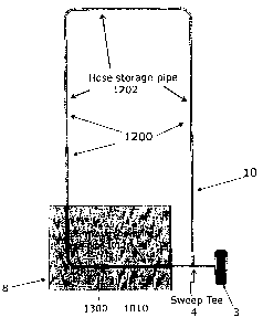
Figure 17 shows a simplified schematic drawing of the vacuum system 10 with
the
hose storage pipe 1202 constituting the hose storage area 1200. The waste
conveying pipe
1012 constituting the waste conveying portion 1010 is shown being separate
from the hose
storage area 1200. The vacuum inlet valve 1300 is shown behind the wall 8 and
intermediate the waste conveying portion 1010 and hose storage area 1200. As
also
illustrated in Figure 17, the system 10 comprises a vacuum source 3 which may
have a
standard canister 9 having a bag or other receptacle to receive the waste that
is entrained in
the vacuum during cleaning. As also illustrated in Figure 17, the hose storage
portion 1200
and waste conveying portion 1010 are in vacuum communication with the vacuum
source 3
through the sweep tee 4 which is remote from the vacuum inlet valve 1300 such
as at a
distance greater than the length of the hose 100. In this way, the same vacuum
source 3 can
provide a vacuum V for the waste conveying portion 1010, to entrain waste
during
cleaning, as well as the hose storage area 1200, to retract the hose during
storage, such that
the waste conveying portion 1010 and the hose storage area 1200 are separate
from each
other but still in vacuum communication.
Figures 18 and 19 illustrate how the vacuum V generated by the vacuum source 3
is
separated by the sweep tee 4 between the hose access area 1200 and the waste
conveying
portion 1010. In particular, Figure 18 shows the hose 100 removed from the
hose storage
area 1200 and the hose access door 330 closed so that the system 10 may be
operated as
before utilizing the wand 800 connected to the wand connection 120 at the
second end 102
of the hose 100. The hose cuff 110 at the first end 101 of the hose 100 is
connected to the
vacuum connection opening 310 of the standard dual volt inlet valve 301. In
this
embodiment, the hose 100 is a current carrying hose and therefore the hose
cuff 110 and the
wand 800 will have a high voltage electrical connection 121 as outlined above
to carry high
voltage current from the high voltage connection 320 of the standard dual volt
inlet valve
301 and a low voltage electrical connection 122 as discussed above.
Because of the hose access door 330 and seal 530, there is no air flow in the
hose
storage pipe 1202, which constitutes the hose storage area 1200 in this
embodiment, while
the standard dual volt inlet valve 301 is in use. Therefore, the seal 530 in
the hose access
13
CA 02885153 2015-03-17
door 330 causes a vacuum seal on the hose storage area 1200, which is
represented by the
"X" in Figure 18 preventing fluid flow in the hose storage area 1200 even when
the
standard dual-volt inlet valve 301 is in use. This is to be contrasted with
the storage area
200 in the embodiment of the vacuum inlet valve 300 shown above, where there
is fluid
flow, and also entrained waste in the hose storage area 200, when the standard
dual-volt
inlet valve 301 is in use.
In the vacuum inlet valve 1300 shown in Figure 18, during cleaning, dirt and
dust
will become entrained in the vacuum V created by the vacuum source 3 and will
be sucked
through the hose 100, the hose cuff 110, the vacuum inlet connection opening
310 of the
standard dual volt inlet valve 301 and then through the waste conveying
portion 1010 for
collection in the canister 9 of the vacuum source 3. As such, no waste, such
as dust and
dirt, will pass through the hose storage area 1200 in this embodiment. In this
way, the hose
storage area 1200 will be maintained somewhat cleaner than the waste conveying
portion
1010, and thus avoiding waste, such as dust and dirt, coming into contact with
the hose 100
during storage.
Figure 19 illustrates storage of the hose 100 with the vacuum inlet valve
1300.
Similar to the above, the second end 102 of the hose 100 is initially manually
inserted into
the hose access chamber 370 and through the hose access opening 332. The
second end
102 is placed near, including possibly into, the hose storage area 1200. The
vacuum system
is then activated using the manual switch 340 to create a vacuum V in the hose
storage
area 1200 as shown in Figure 19. As shown in Figure 19, a suction will also be
created in
the waste conveying portion 1010, but because the hose cuff 110 is connected
to the
vacuum inlet 301, no air will pass through the waste conveying portion 1010,
which is
represented by the "X" in Figure 19, because the second end 102 is
experiencing a similar
vacuum V in the hose storage area 1200. Rather, the vacuum V generated by the
system 10
will retract the second end 102 of the hose 100 into the hose storage area
1200. The rear
surface 111 of the hose cuff 110 is abutting against the abutment surface 210
to avoid
further retraction of the hose 100 into the hose storage area 1200 as
discussed above. The
door 330 will then be closed creating a vacuum seal so that other vacuum inlet
valves (not
shown) in the system 10 can be used without degradation of the vacuum. When
the hose
14
CA 02885153 2015-03-17
access door 330 is closed, the manual switch 340 will also be covered to avoid
accidental
operation of the switch 340 and any unintended activation of the vacuum source
3 of the
central vacuum system 10.
Figures 21, 22a, 22b and 23 show further embodiment of the present invention
where the chamber 2370 is shown as being separate from the standard dual volt
inlet valve
2301. This embodiment of the present invention relates to a vacuum inlet
valve, shown
generally by reference numeral 2300, where the hose access chamber 2370 is
separate from
the standard dual volt inlet valve 2301. As illustrated in Figures 22a and
22b, this can be
used in cases where the hose storage area, shown by reference numeral 2200 in
Figures 22a
and 22b, is installed on existing vacuum system 10 and there is no room for a
hose storage
area 2200 near the standard dual-volt inlet valve 2301. In this case, the hose
storage area
2200 may be retroactively stored onto the existing vacuum system 10. The
storage area
2200 may be constituted by an add-on storage piping 2202 in cases where the
storage area
2200 does not have another location. The waste conveying portion, in this
embodiment
illustrated by reference numeral 2010, may be constituted by a waste conveying
piping
2012 which in this embodiment may be an existing waste conveying piping 2012,
in cases
where the vacuum inlet valve 2300 has been retrofitted.
Figure 23 shows a further embodiment of the hose access chamber 2370 of the
vacuum inlet valve shown in Figures 21, 22a and 22b. As shown in Figure 23,
the hose
access chamber 2370 is separate from the standard dual volt inlet valve 301.
The hose
access chamber 2370 has hose cuff compartment 220, a hose storage area opening
202 and
the abutment surface 210. As such, the hose access chamber 2370 can store the
hose cuff
110 in the hose cuff compartment 220 with the rear surface 111 of the hose
cuff 110
abutting against the abutment surface 210 to prevent further retraction of the
hose 100 into
the hose storage area 2200. Similarly, the door 330 of the hose access chamber
2370 has a
seal 530 to create a vacuum seal in the hose cuff compartment 220 in the hose
storage area
2200. When the hose access door 330 is closed, a portion 331 will cover the
manual switch
340 to prevent accidental activation of the switch 340 while the hose 100 is
in the stored
position.
To the extent that a patentee may act as its own lexicographer under
applicable law,
CA 02885153 2015-03-17
it is hereby further directed that all words appearing in the claims section,
except for the
above defined words, shall take on their ordinary, plain and accustomed
meanings (as
generally evidenced, inter alia, by dictionaries and/or technical lexicons),
and shall not be
considered to be specially defined in this specification. Notwithstanding this
limitation on
the inference of "special definitions," the specification may be used to
evidence the
appropriate, ordinary, plain and accustomed meanings (as generally evidenced,
inter alia,
by dictionaries and/or technical lexicons), in the situation where a word or
term used in the
claims has more than one pre-established meaning and the specification is
helpful in
choosing between the alternatives.
It will be understood that, although various features of the invention have
been
described with respect to one or another of the embodiments of the invention,
the various
features and embodiments of the invention may be combined or used in
conjunction with
other features and embodiments of the invention as described and illustrated
herein.
Although this disclosure has described and illustrated certain preferred
embodiments of the invention, it is to be understood that the invention is not
restricted to
these particular embodiments. Rather, the invention includes all embodiments,
which are
functional, electrical or mechanical equivalents of the specific embodiments
and features
that have been described and illustrated herein.
16