Note: Descriptions are shown in the official language in which they were submitted.
CA 02885978 2015-03-23
TAMPER EVIDENT CONTAINERS WITH LID TABS
BACKGROUND OF THE INVENTION
FIELD OF THE INVENTION
100011 The present disclosure relates to tamper evident containers
DESCRIPTION OF THE RELATED ART
[0002] This application incorporates by reference U.S. Patent Application No.
13/681,017,
which was filed on November 19, 2012 and is titled TAMPER EVIDENT CONTAINERS.
BRIEF DESCRIPTION OF THE DRAWINGS
[0003] The written disclosure herein describes illustrative embodiments that
are non-limiting
and non-exhaustive. Reference is made to certain of such illustrative
embodiments that are
depicted in the figures, in which:
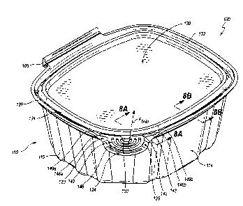
[0004] FIG. 1 is a perspective view of an embodiment of a tamper evident
container in a
closed pre-use configuration.
[0005] FIG. 2 is a perspective view of the tamper evident container of FIG. 1
in a closed
configuration with the lid tab lifted such that it is partially separated from
the lid and is ready
to be grasped to open the container by lifting the lid away from the base.
[0006] FIG. 3 is a perspective view of the tamper evident container of FIG. 1
in an open
configuration with the lid pivoted away from the base.
[0007] FIG. 4 is a perspective view of the tamper evident container of FIG. 1
that has been
closed after being opened and with the lid tab and the indicator tab pivoted
upward to show
that the container has been opened.
CA 02885978 2015-03-23
[0008] FIG. 5 is a perspective view of the tamper evident container of FIG. 1
that has been
closed after being opened and the lid tab bent back into shape but with the
indicator tab still
pivoted upward to show that the container has been opened.
[0009] FIG. 6 is a side view of the tamper evident container of FIG. 1 that
has been closed
after being opened and the lid tab and the indicator tab are still pivoted
upward to show that
the container has been opened.
[0010] FIG. 7 is a plan view of the tamper evident container of FIG. 1 in an
open preloading
configuration.
[0011] FIG. 7A is an enlarged plan view of a lid tab, an indicator tab, and a
portion of a lid
of the container of FIG. 1, taken along the view line 7A in FIG. 7.
[0012] FIG. 8 is a cross-sectional view of another portion of the tamper
evident container of
FIG. 1 taken along the view line 8-8 in FIG. 1.
[0013] FIG. 9 is a diagram that shows the material strain of the indicator tab
as the lid tab is
pulled and pivoted and also the force applied amount of force required to
deform the indicator
legs of the lid tab and the amount of force to dislodge the lid from the base
to open the
container.
[0014] FIG. 10 is a perspective view of another embodiment of a tamper evident
container in
a closed pre-use configuration that differs from the embodiment shown in FIG.
1 based on the
lack of an indicator tab.
[0015] FIG. 11 is a perspective view of the tamper evident container of FIG.
10 in a closed
configuration with the lid tab lifted such that it is partially separated from
the lid and is ready
to be grasped to open the container by lifting the lid away from the base.
[0016] FIG. 12 is a perspective view of the tamper evident container of FIG.
10 in an open
configuration with the lid pivoted away from the base.
2
CA 02885978 2015-03-23
[0017] FIG. 13 is a diagram that shows the material strain of the lid tab when
the container is
opened by pulling and pivoting the lid tab to overcome the lip seal of the lid
and the base and
also shows the material strain when the lid is opened again after being
closed. The diagram
also shows the force applied to the lid tab to release the lid from the base
at the lip seal.
[0018] FIG. 14 is a perspective view of another embodiment of a tamper evident
container,
which differs from the embodiment shown in FIG. 1 as it has a lid tab that is
colored and has
a different shape
[0019] FIG. 14A is an enlarged perspective view of a lid tab, an indicator
tab, and a portion
of a lid of the container of FIG. 14, taken along the view line 14A in FIG.
14.
[0020] FIG. 14B is an enlarged perspective view of the tamper evident
container of FIG. 14B
taken along the view line 14A in FIG. 14 showing the lid opened pivoted and
ready to be
pulled to open the container by pivoting the lid away from the base.
[0021] FIG. 14C is an enlarged perspective view of the tamper evident
container as shown in
FIG. 14B viewed at a different angle.
[0022] FIG. 15 is a perspective view of the tamper evident container of FIG.
14 in an open
configuration with the lid pivoted away from the base and ready to be closed
again.
[0023] FIG. 16 is a perspective view of the tamper evident container of FIG.
14 that has been
closed after being opened and the lid tab bent back into shape but with the
indicator tab still
pivoted upward to show that the container has been opened.
[0024] FIG. 16A is an enlarged perspective view of the tamper evident
container of FIG. 16
taken along the view line 16A in FIG. 16
[0025] FIG. 17 is a plan view of the tamper evident container of FIG. 14 in an
open
preloading configuration.
[0026] FIG. 17A is an enlarged plan view of a lid tab, an indicator tab, and a
portion of a lid
of the container of FIG. 17, taken along the view line 17A in FIG. 17.
3
CA 02885978 2015-03-23
4 44ate)µe 6110-^A\(--
CA 02885978 2015-03-23
DETAILED DESCRIPTION OF THE PREFERRED EMBODIMENTS
[0027] The embodiments disclosed herein relate to containers that may be used,
for example,
in the food industry. In particular, certain embodiments disclosed herein
relate to tamper
evident containers that may be used for storing and/or transporting food
products. It will be
readily understood that the components of the present disclosure, as generally
described and
illustrated in the drawings herein, could be arranged and designed in a wide
variety of
different configurations. Thus, the following more detailed description of the
embodiments is
not intended to limit the scope of the disclosure, but is merely
representative of possible
embodiments of the disclosure. While various aspects of certain embodiments
are presented
in drawings, the drawings are not necessarily drawn to scale.
[0028] Certain embodiments can advantageously be supplied to an intermediary
user in an
open preloading configuration (e.g., FIG. 6). The intermediary user can load
the container
with any desired item, such as a food product, and can then close the
container into a closed
pre-use configuration (e.g., FIG. 1). When in this state, the container can be
resistant to
opening at any region other than an opening region, which can be provided with
a tamper
evident tab. Accordingly, in some embodiments, an end user can ultimately
access the
packaged contents of the container using the tamper evident tab. The tab can
be pulled to
assist in separating primary components of the container (e.g., a lid and a
base) from each
other. The tab can remain coupled with one of the primary components of the
container (e.g.,
the lid), but can be partially separated from a neighboring region thereof in
such a way as to
indicate that the tab has been used (e.g., FIG. 4). As the tab is pulled
further, the package can
be opened from the pre-use configuration into an open post-use configuration
(e.g., FIG. 3).
Further details of embodiments of tamper evident containers are provided
below.
[0029] FIG. 6 depicts an embodiment of a tamper evident container 100 shown in
an open
preloading configuration. As illustrated in FIGS. 1-6A, the container 100 can
include a base
CA 02885978 2015-03-23
110 and a lid 130. In some embodiments, the base 110 and the lid 130 may be
connected or
otherwise adjoined to one another. For example, the base 110 and the lid 130
may be
connected via a hinged portion or hinge 105. In some embodiments, the base
110, the lid
130, and the hinge 105 may be integrally formed from a unitary piece of
material. For
example, in some embodiments the container 100 is formed from a single piece
of
thermoformed plastic. In other embodiments, the base 110 and the lid 130 may
not be
connected to one another at all; rather, the base 110 and the lid 130 may each
comprise
individual and fully separable components.
[0030] As shown in FIG. 1, the base 110 may include a bottom end 112. The
bottom end
112 can have any suitable shape and configuration. For example, in some
embodiments at
least a portion of the bottom end 112 is substantially planar. In the
illustrated embodiment,
the bottom end 112 includes a contact surface 111 and a raised platform 113.
At least a
portion of the contact surface 111 may be substantially planar such that the
base 110 may
readily rest upon a planar surface. The raised platform 113 may be upwardly
offset relative
to the contact surface 111. Other suitable configurations for the bottom end
112 are also
contemplated.
[0031] The base 110 may further include a sidewall 114 that extends upwardly
from the
bottom end 112. The bottom end 112 and the sidewall 114 can cooperate to
define a cavity
116. The base 110 may be generally bowl-shaped, although other shapes and
configurations
are possible. In some embodiments, the sidewall 114 may extend upwardly in a
substantially
vertical manner that it is substantially perpendicular to the bottom end 112.
In other
embodiments, the sidewall 114 may extend upwardly and may be angled radially
outwardly.
For example, the sidewall 114 may extend upwardly in a radially outward
direction at an
angle of about 5 degrees to about 10 degrees, or from about 5 degrees to about
15 degrees. In
yet other embodiments, the sidewall 114 may extent upwardly in a curved or
arcuate manner.
6
CA 02885978 2015-03-23
Accordingly, as can be appreciated, the sidewall 114 may extend upwardly in a
variety of
ways depending on the desired shape and characteristics of the container 100.
[0032] The sidewall 114 may be substantially uniform or flat, or it may
comprise one or
more features for reinforcement, grip assistance, etc. For example, in the
illustrated
embodiment, the sidewall 114 comprises a plurality of substantially vertically
oriented ribs
115. The ribs 115 may provide the base 110 with strength and/or may augment
its rigidity.
[0033] The base 110 of the container 100 may further comprise a base
connection interface
118 disposed at an upper end of the sidewall 114. The base connection
interface 118 may be
configured to interact with portion the lid 130 so as to close the container
100, as further
discussed below. In some embodiments, the base connection interface 118 may
extend about
at least a majority of a periphery of the sidewall 114. For example, in
various embodiments,
the base connection interface 118 may extend about at least 1/2, 2/3, or 3/4
of a total
periphery of the upper end of the sidewall 114. In further embodiments, the
base connection
interface 118 may extend about an entirety of the periphery of the sidewall
114. In yet other
embodiments, the base connection interface 118 may extend around a smaller
portion of the
sidewall 114.
[0034] A base flange 120 can extend outwardly relative to the base connection
interface 118.
The base flange 120 may be directly connected to or otherwise coupled with an
upper end of
the base connection interface 118. Accordingly, the base flange 120 may be
configured such
that it is at a higher position than is base connection interface 118, as
compared with to the
bottom end 112. In the illustrated embodiment, the base flange 120 is
positioned at an upper
end of the base connection interface 118, and the base flange 120 extends
radially outwardly
in a horizontal direction from the base connection interface 118 (see also
FIG. 3). In other
embodiments, the base flange 120 may be at about the same height, or may be
lower than, the
connection interface 118 relative to the bottom end 112.
7
CA 02885978 2015-03-23
[0035] At least a portion of the base flange 120 can be flat or planer. For
example, in the
illustrated embodiment, the base flange 120 defines a plane that is parallel
to the plane
defined by the bottom end 112. The planar portion of the base flange 120 may
extend about
at least a majority of the perimeter of the base. In some embodiments, at
least a majority of
the base flange 120 may be substantially planar. In yet other embodiments,
only a portion of
the base flange 120 may be substantially planar.
[0036] In other embodiments, the base flange 120 may have configurations that
are non-
planar and/or multi-planar. For example, the base flange 120 may extend
upwardly at an
angle relative to a horizontal plane (e.g., at an angle no less than about 30,
45, 60, or 75
degrees). Depending on the shape of the container, the base flange 120 may
have
substantially planar regions, substantially conical regions, and or regions
that define other
shapes. For example, where the base flange 120 extends upwardly at a constant
angle along
the periphery of the container 100 at each radial position, and the container
is substantially
rectangular, the upwardly extending flange 120 may define a different plane
along each of the
linear regions of the rectangle, and the flange 120 may define substantially
conical regions at
the corners that connect adjacent planar regions. As another example, where
the base flange
120 extends upwardly at a constant angle along the periphery of the container
100 at each
radial position, and the container is substantially circular, the flange 120
may define a
substantially conical region that extends about at least a majority of the
periphery of the base
110. Other arrangements are also contemplated.
[0037] The base flange 120 may further comprise a free edge 122 that defines
at least a
portion of the outermost perimeter of the base 110. In some embodiments, the
free edge 122
may extend about at least a majority of the outermost periphery of the
sidewall 114. In the
illustrated embodiment, for example, the free edge 122 extends about the
outermost periphery
of the sidewall 114 everywhere other than at the hinged portion 105. In other
embodiments,
8
CA 02885978 2015-03-23
the free edge 122 may extend about the entirety of the outermost periphery of
the sidewall
114. The free edge 122 of the base flange 120 may therefore extend about at
least a majority,
up to and including the entirety, of the outermost perimeter of the base 110.
[0038] With continued reference to FIG. 1, in some embodiments, the base
flange 120
includes a recessed region 124. The recessed region 124 may be offset from
neighboring
portions of the base flange 120. In some embodiments, at least a portion of
the recessed
region 124 defines a plane. For example, in the illustrated embodiment, the
recessed region
124 defines a plane that is parallel to a plane that is defined by neighboring
portions of the
base flange 120. The illustrated recessed region 124 is downwardly offset but
otherwise
parallel to the neighboring portions of the base flange 120. Accordingly, the
recessed region
124 may be below or otherwise spaced from or outside of a plane defined by at
least a portion
of remaining portions of the base flange 120. As further illustrated in FIG.
1, the free edge
122 may extend along the outermost periphery of the recessed region 124 as
well as the
outermost periphery of the neighboring portions of the base flange 120. The
base flange 120
may also include optional friction features such as ribs 126.
[0039] The lid 130 can include a lid connection interface 132 that is
configured to interact
with a complementary or otherwise cooperative portion of the base 110. For
example, the lid
connection interface 132 may be configured to selectively couple with the base
connection
interface 118. In some embodiments, the connection interfaces 132, 118 are
complementary
in shape (see FIG. 7), and the lid connection interface 132 and the base
connection interface
118 may be substantially the same shape, size and conformation. In some
embodiments, the
lid connection interface 132 may be configured to be received by the base
connection
interface 118, and it may be slightly larger than the base connection
interface 118 to assist in
providing a tight seal therewith. In other embodiments, the base connection
interface 118
may be configured to be received by the lid connection interface 132.
9
CA 02885978 2015-03-23
[0040] The lid connection interface 132 may extend about at least a majority
of the periphery
of the lid 130. In some embodiments, the lid connection interface 132 may also
extend about
the entire periphery of the lid 130. When the container 100 is in a closed
configuration, the
lid 130 and the base 110 may be coupled or otherwise attached such that the
cavity 116
defined by the base 110 is closed by the lid 130, or stated otherwise, is
enclosed by the lid
130 and the base 110.
[0041] The lid 130 can include a lid flange 134 that may extend outwardly
relative to the lid
connection interface 132. In some embodiments, the lid flange 134 may be
directly
connected to an end of the lid connection interface 132. The lid flange 134
may have a free
edge 136 that may define at least a portion of the outermost perimeter of the
lid 130. In some
embodiments, the lid free edge 136 may extend about at least a majority of, up
to and
including the entirety of, the outermost perimeter of the lid 130.
[0042] With continued reference to FIG. 1, and with additional reference to
FIG. 2, at least a
portion of the lid flange 134 can be flat or planer. For example, in the
illustrated
embodiment, the lid flange 134 defines a plane that is parallel to the plane
defined by the
majority of the base flange 120 when the container 100 is in the closed pre-
use configuration
shown in FIG. 2. The planar portion of the lid flange 134 may extend about at
least a
majority of the perimeter of the lid 130. In some embodiments, at least a
majority of the lid
flange 134 may be substantially planar. In yet other embodiments, only a
portion of the lid
flange 134 may be substantially planar.
100431 In other embodiments, the lid flange 134 may have configurations that
are non-planar
and/or multi-planar. For example, the lid flange 134 may extend upwardly at an
angle
relative to a horizontal plane (e.g., at an angle no less than about 30, 45,
60, or 75 degrees)
when the container 100 is in the closed pre-use configuration shown in FIG. 2.
Depending on
the shape of the container, the lid flange 134 may have substantially planar
regions,
CA 02885978 2015-03-23
substantially conical regions, and or regions that define other shapes. For
example, where the
lid flange 134 extends upwardly at a constant angle along the periphery of the
container 100
at each radial position, and the container is substantially rectangular, the
upwardly extending
flange 134 may define a different plane along each of the linear regions of
the rectangle, and
the flange 134 may define substantially conical regions at the corners that
connect adjacent
planar regions. As another example, where the lid flange 134 extends upwardly
at a constant
angle along the periphery of the container 100 at each radial position, and
the container is
substantially circular, the flange 134 may define a substantially conical
region that extends
about at least a majority of the periphery of the base 110. In various of the
foregoing
embodiments, the lid flange 134 may be substantially parallel to the base
flange 120, whether
in the planar or non-planar regions. Other arrangements are also contemplated.
[0044] With continued reference to FIGS. 1 and 2, the lid 130 can also include
a lid tab 140.
The tab may have any suitable shape. For example, FIGS. 14-17A show an
embodiment with
a lid tab 340 that has a different shape relative to lid tab 140. The tab 140
can have opposite
surfaces 146, 147 that are configured to be gripped by a user and may
optionally include
friction features such as ribs. In the illustrated embodiment, the surface 146
is referred to as
the lower surface and the surface 147 is referred to as the upper surface,
with the terms
"upper" and "lower" referring to the arrangement depicted in FIG. 1 in which
the container
100 is in a closed orientation. In some embodiments, the tab 140 can be
substantially planar,
and in further embodiments, the tab 140 may be co-planar with the lid flange
134. In some
embodiments, the tab 140 may be connected to, integral with, or otherwise
associated with
the lid flange 134. The free edge 136 of the lid 130 may extend along a
periphery of the tab
140.
[0045] The lid flange 134 may have a weakened region that borders a portion of
the tab 140.
This weakened region 134 may allow for controlled separation (e.g., tearing)
of a portion of
11
CA 02885978 2015-03-23
the tab 140 from the lid flange 134. The weakened region 134 may further act
as an indicator
for demonstrating that the container 100 has been opened or otherwise tampered
with, as
discussed further below.
[0046] FIGS. 1 depicts the container 100 in an initial closed configuration,
which may also
be referred to as a closed pre-use configuration. In the illustrated
embodiment, the tab 140 is
positioned over the recessed region 124 of the base flange 120. By positioning
the tab 140
over the recessed region 124, the tab 140 may cooperate with the recessed
region 124 to
define or create an opening 125 that is accessible from a lateral side of the
container 100. For
example, due to the expanded spacing between the lid flange 134 and the base
flange 120 in
the vicinity of the recessed region 124, a user to insert a portion of a
finger (e.g., a tip or a
side portion of a thumb or index finger) between the free edge 136 of the lid
130 and the free
edge 122 of the base 110 and into the opening 125 so as to grasp the opposite
surface 146,
147 of the tab 140. In various embodiments, opening 125 has a height H of no
less than
about 1, 2, 3, 4, 5, 10, 15, or 20 millimeters; no greater than about 1,2, 3,
4, 5, 10, 15,
or 20 millimeters; or between about 1 and about 20 millimeters, between about
1 and
about 15 millimeters, or between about 1 and about 10 millimeters. In some
embodiments,
the height H is about 2.2 millimeters.
[0047] As further shown in FIGS. 6A, the lid 130 may include a weakened region
142 that
borders a portion of the tab 140. The weakened region 142 may include any
suitable form of
weakening, such as a frangible line, a line of perforation, and/or a region of
reduced
thickness. In the illustrated embodiment, the weakened region 142 comprises a
line of
perforation 143. The weakened region 142 can permit controlled separation of
the tab 140
from a neighboring portion of the lid flange 134. The weakened region 142 can
be situated
so as to prevent full separation of the tab 140 from the lid flange 134. For
example, as shown
in FIG. 1 and FIG. 6A, the illustrated line of perforation does not extend all
the way to the
12
CA 02885978 2015-03-23
outer edge 136 of the lid flange 134. As a result, the material of which the
lid flange 134 is
formed (e.g., plastic) can act as a stop to prevent tearing to extend beyond
the end of the line
of perforation 143. In various embodiments, a width, thickness, and/or
strength of a portion
of the material that is positioned between the end of the line of perforation
143 and the outer
edge of the lid flange 134 can be sufficient to prevent further tearing once
the perforated
portion has been separated. In view of the foregoing, the tab 140 may be
configured to be
partially separated from a neighboring portion of the lid flange 134 along the
weakened
region 142 yet remain coupled with the lid 130 and assist in uncoupling the
lid 130 from the
base 110 when being pulled upon by a user.
[0048] Separation of the tab 140 along the weakened region 142 can indicate
whether the
container has been opened or otherwise tampered with. For example, separation
of the tab
140 along the weakened region 142 may indicate that the lid 130 has been
uncoupled from
the base 110 to transition out of the closed pre-use configuration, as
discussed further below
with respect to FIG. 3. In the illustrated embodiment, as depicted in FIG. 1
the lid 130 has
been closed to the base 110 after an initial filling of the base 110, but the
lid 130 has not yet
been uncoupled from the base 110, as evidenced by the fact that the weakened
region 142 is
unbroken.
[0049] An arrangement such as depicted in FIGS. 2 and 3 can be intuitive for a
user to
manipulate. For example, some known containers include a tab at an edge
thereof that a user
grasps in order to open the container. The user can generally grasp such a tab
directly from
the outer edge of the container, such as by advancing a finger radially
inwardly under the tab.
The user may pinch opposite surfaces of the tab between two fingers (e.g., an
index finger
and a thumb) and pull on the tab to open the container. With an arrangement
such as shown
in FIG. 1, the user can intuitively understand operation of the tamper-evident
tab 140. The
user can naturally access opposing surfaces of the tab directly from the outer
edge of the
13
CA 02885978 2015-03-23
container 100 by inserting a finger into the opening 125 to grasp the opposite
surfaces 146,
147 of the tab 140, and then the user can pull upwardly on the tab 140 in a
typical fashion.
[0050] In some embodiments, the container 100 can include further features to
aid the user in
readily using the tab 140. For example, the tab 140 may include any suitable
indicia for
indicating that the container 100 is opened by pulling on the tab 140. The tab
140 may
include writing, coloring, or other instructive markings. In the embodiment
illustrated in
FIGS. 14-17A, the tab 140 is colored (e.g., with ink of any desired color ¨
blue, etc.) to draw
the user's attention to the tab 140. In the illustrated embodiment, other
portions of the
container 100 may be substantially transparent or translucent, such that the
colored tab 140
may highly contrast with the remaining portions of the container 100.
[0051] In some embodiments, such as that illustrated in FIG. 3, the tab 140
can be positioned
above the base flange 122, and the base flange 122 can extend outwardly at
least slightly
beyond a profile of the tab 140. Such an arrangement can inhibit inadvertent
contact with the
tab 140 that might break the weakened area 142. For example, the base flange
122 may act
as a guard against bumping of the tab 140 that might otherwise result from
transport or
handling of the container 100.
[0052] FIG. 8A is a cross-sectional view of a portion of the container 100
further illustrating
the opening 125 or gap created between the tab 140 and the recessed region 124
of the base
flange 120. FIG. 8A also depicts an illustrative example of the manner in
which the base
connection interface 118 and the lid connection interface 132 may be
selectively coupled to
one another thereby attaching the lid 130 to the base 110 while the container
100 is in a
closed configuration. In particular, in the illustrated embodiment, the base
connection
interface 118 defines a rounded recess 160 and the lid connection interface
132 defines a
rounded protrusion 162. The rounded recess 160 is substantially complementary
to the
14
CA 02885978 2015-03-23
rounded protrusion 162 and is configured to receive the rounded protrusion 162
therein in
locking engagement. Any other suitable locking configuration is contemplated.
[0053] FIG. 8B is a cross-sectional view of another portion of the container
100 when the
container is in the closed configuration of FIG. 1. The portion of the
container 100 that is
depicted is at a position spaced from the tab 140. As shown, the lid flange
134 can be
positioned above the base flange 120. The lid flange 134 may be recessed
relative to the base
flange 120. In the illustrated arrangement, both the free edge 136 of the lid
flange 134 and
the free edge 122 of the base flange 120 are exposed so as to be contactable
by a user.
However, in the illustrated embodiment, the relative dimensions of the lid
flange 134 and the
base flange 120 are such that the flanges 120, 134 cannot be adequately
grasped in order to
separate the lid 130 from the base 110. Accordingly, it may be difficult to
separate the lid
130 from the base 110 or otherwise open the container 100 without the use of
the tab 140. In
some instances, attempts to grasp the flanges 120, 134 in regions spaced from
the tab 140,
such as shown in FIG. 5, can bend, distort, or otherwise plastically deform
the flanges 120,
134 to indicate that an access attempt or event has taken place.
[0054] As shown in FIG. 8B, a plane defined by the base flange 120 can be
parallel to a
plane defined by the lid flange 134. Other arrangements, including other
parallel
arrangements, are also possible (such as discussed above).
[0055] FIG. 2 depicts the tamper evident container 100 in the closed pre-use
configuration.
The tab 140 has been lifted so as to separate it from neighboring portions of
the lid flange
120. As can be seen, the weakened region 142 has been broken and the tab 140
has been
lifted in the direction indicated by the arrow. Accordingly, the separation of
the tab 140
along the weakened region 142 indicates that the container 100 may have been
tampered with
and that the lid 130 may have been uncoupled from the base 110. As further
shown, the tab
140 is bent relative to the neighboring portions of the lid flange 134. In the
illustrated
CA 02885978 2015-03-23
embodiment, although the tab 140 has been bent, the tab 140 still remains
substantially
planar, although the plane that it defines is angled relative to the plane of
the neighboring
portions of the lid flange 134. The tab 140 may continue to be grasped by a
user, and
additional pulling can uncouple the lid 130 from the base 110 into the
arrangement shown in
FIG. 7.
100561 In some embodiments, pulling on the tab 140 into the position shown in
FIG. 6 can
plastically deform at least a portion of the lid flange 134. For example, in
some
embodiments, the tab 140 may remain in the lifted position due to the plastic
deformation,
such as permanent bending.
[0057] FIG. 3 depicts the tamper evident container 100 in an open post-use
configuration.
As can be seen in FIG. 2, following separation of the tab 140 along the
weakened region, the
tab 140 may be grasped and pulled in the direction of the arrow by a user such
that the lid 130
may be removed from the base 110.
100581 After the container 100 has been transitioned to the open post-use
configuration, it
may be closed again, and thereby transitioned to a closed post-use
configuration. For
example, the connection interfaces 118, 132 and the base 110 and the lid 130,
respectively,
can be configured to repeatedly engage with each other and disengage from each
other.
When in the closed post-use configuration, the tab 140 may remain in a
displaced state. For
example, in some embodiments, the container 100 may look substantially like
what is
depicted in FIG. 4, with the tab 140 in a raised or lifted state. In other
embodiments, the tab
140 may return to a coplanar state with neighboring portions of the lid flange
134, or the tab
140 may otherwise be generally continuous with the neighboring portions of the
lid flange
134, although the broken or tom weakened area may remain in a severed state to
indicate that
an opening event has occurred.
16
CA 02885978 2015-03-23
[0059] Lid tab includes legs 148a and 148b with terminal portions 149a and
149b that extend
to stops, as described above. Terminal portions 149a and149b become elongated
when lid
130 is pivoted to open container 100. Terminal portions 149a and 149b extend
beyond their
elastic limit and yet remain sufficient structural integrity to allow lid tab
140 to be grasped
and overcome the interaction of the lip seal. Once the line of weakness or
perforation 143
has been opened, an opening 141 is formed and the legs 148a and 148b form a
stirrup-like
configuration. In one embodiment it takes about 2lbs to deform terminal
portions 149a and
149b and about Sibs to open the container. One of the advantages of this
configuration is that
the deformation and opening occur in the same movement. Also, any jagged edges
perforation 143 are not exposed.
[0060] FIGS. 10-12 depict another embodiment of a tamper evident container 200
and FIGS.
14-17A depict an additional embodiment of a tamper evident container 300. The
container
200 and container 300 can resemble the container 100 discussed above with
respect to FIGS.
1-8B. It will be appreciated that the illustrated embodiments may have
analogous features.
Accordingly, like features are designated with like reference numerals, with
the leading digits
incremented to "2" or "3". Relevant disclosure set forth above regarding
similarly identified
features thus may not be repeated hereafter. Moreover, specific features of
the container and
related components shown in FIGS. 10-12 and FIGS. 14-17A may not be shown or
identified
by a reference numeral or specifically discussed in the written description
that follows.
However, such features may clearly be the same, or substantially the same, as
features
depicted in other embodiments and/or described with respect to such
embodiments.
Accordingly, the relevant descriptions of such features apply equally to the
features of the
container 200 and container 300. Any suitable combination of the features, and
variations of
the same, described with respect to the container 100 and components
illustrated in FIG. 1,
can be employed with the container and components of FIG. 2, and vice versa.
This pattern
17
CA 02885978 2015-03-23
of disclosure applies equally to further embodiments depicted in subsequent
figures and
described hereafter.
[0061] Any methods disclosed herein comprise one or more steps or actions for
performing
the described method. The method steps and/or actions may be interchanged with
one
another. In other words, unless a specific order of steps or actions is
required for proper
operation of the embodiment, the order and/or use of specific steps and/or
actions may be
modified.
[0062] References to approximations are made throughout this specification,
such as by use
of the terms "about" or "approximately." For each such reference, it is to be
understood that,
in some embodiments, the value, feature, or characteristic may be specified
without
approximation. For example, where qualifiers such as "about," "substantially,"
and
"generally" are used, these terms include within their scope the qualified
words in the
absence of their qualifiers. For example, where the term "substantially
planar" is recited
with respect to a feature, it is understood that in further embodiments, the
feature can have a
precisely planar configuration.
[0063] Reference throughout this specification to "an embodiment" or "the
embodiment"
means that a particular feature, structure or characteristic described in
connection with that
embodiment is included in at least one embodiment. Thus, the quoted phrases,
or variations
thereof, as recited throughout this specification are not necessarily all
referring to the same
embodiment.
[0064] Similarly, it should be appreciated that in the above description of
embodiments,
various features are sometimes grouped together in a single embodiment,
figure, or
description thereof for the purpose of streamlining the disclosure. This
method of disclosure,
however, is not to be interpreted as reflecting an intention that any claim
require more
features than those expressly recited in that claim. Rather, as the following
claims reflect,
18
CA 02885978 2015-03-23
inventive aspects lie in a combination of fewer than all features of any
single foregoing
disclosed embodiment.
[0065] The claims following this written disclosure are hereby expressly
incorporated into
the present written disclosure, with each claim standing on its own as a
separate embodiment.
This disclosure includes all permutations of the independent claims with their
dependent
claims. Moreover, additional embodiments capable of derivation from the
independent and
dependent claims that follow are also expressly incorporated into the present
written
description.
[0066] Recitation in the claims of the term "first" with respect to a feature
or element does
not necessarily imply the existence of a second or additional such feature or
element.
Elements specifically recited in means-plus-function format, if any, are
intended to be
construed in accordance with 35 U.S.C. 112 6. Embodiments of the invention
in which
an exclusive property or privilege is claimed are defined as follows.
19